EP0361111A2 - Connexion embrochable pour des guides d'ondes lumineuses - Google Patents
Connexion embrochable pour des guides d'ondes lumineuses Download PDFInfo
- Publication number
- EP0361111A2 EP0361111A2 EP89115840A EP89115840A EP0361111A2 EP 0361111 A2 EP0361111 A2 EP 0361111A2 EP 89115840 A EP89115840 A EP 89115840A EP 89115840 A EP89115840 A EP 89115840A EP 0361111 A2 EP0361111 A2 EP 0361111A2
- Authority
- EP
- European Patent Office
- Prior art keywords
- sleeve
- union nut
- optical fiber
- connector
- nut
- Prior art date
- Legal status (The legal status is an assumption and is not a legal conclusion. Google has not performed a legal analysis and makes no representation as to the accuracy of the status listed.)
- Granted
Links
Images
Classifications
-
- G—PHYSICS
- G02—OPTICS
- G02B—OPTICAL ELEMENTS, SYSTEMS OR APPARATUS
- G02B6/00—Light guides; Structural details of arrangements comprising light guides and other optical elements, e.g. couplings
- G02B6/24—Coupling light guides
- G02B6/36—Mechanical coupling means
- G02B6/38—Mechanical coupling means having fibre to fibre mating means
- G02B6/3807—Dismountable connectors, i.e. comprising plugs
- G02B6/381—Dismountable connectors, i.e. comprising plugs of the ferrule type, e.g. fibre ends embedded in ferrules, connecting a pair of fibres
- G02B6/3826—Dismountable connectors, i.e. comprising plugs of the ferrule type, e.g. fibre ends embedded in ferrules, connecting a pair of fibres characterised by form or shape
- G02B6/3831—Dismountable connectors, i.e. comprising plugs of the ferrule type, e.g. fibre ends embedded in ferrules, connecting a pair of fibres characterised by form or shape comprising a keying element on the plug or adapter, e.g. to forbid wrong connection
-
- G—PHYSICS
- G02—OPTICS
- G02B—OPTICAL ELEMENTS, SYSTEMS OR APPARATUS
- G02B6/00—Light guides; Structural details of arrangements comprising light guides and other optical elements, e.g. couplings
- G02B6/24—Coupling light guides
- G02B6/36—Mechanical coupling means
- G02B6/38—Mechanical coupling means having fibre to fibre mating means
- G02B6/3807—Dismountable connectors, i.e. comprising plugs
- G02B6/3833—Details of mounting fibres in ferrules; Assembly methods; Manufacture
- G02B6/3834—Means for centering or aligning the light guide within the ferrule
- G02B6/3843—Means for centering or aligning the light guide within the ferrule with auxiliary facilities for movably aligning or adjusting the fibre within its ferrule, e.g. measuring position or eccentricity
-
- G—PHYSICS
- G02—OPTICS
- G02B—OPTICAL ELEMENTS, SYSTEMS OR APPARATUS
- G02B6/00—Light guides; Structural details of arrangements comprising light guides and other optical elements, e.g. couplings
- G02B6/24—Coupling light guides
- G02B6/36—Mechanical coupling means
- G02B6/38—Mechanical coupling means having fibre to fibre mating means
- G02B6/3807—Dismountable connectors, i.e. comprising plugs
- G02B6/3833—Details of mounting fibres in ferrules; Assembly methods; Manufacture
- G02B6/3847—Details of mounting fibres in ferrules; Assembly methods; Manufacture with means preventing fibre end damage, e.g. recessed fibre surfaces
-
- G—PHYSICS
- G02—OPTICS
- G02B—OPTICAL ELEMENTS, SYSTEMS OR APPARATUS
- G02B6/00—Light guides; Structural details of arrangements comprising light guides and other optical elements, e.g. couplings
- G02B6/24—Coupling light guides
- G02B6/36—Mechanical coupling means
- G02B6/38—Mechanical coupling means having fibre to fibre mating means
- G02B6/3807—Dismountable connectors, i.e. comprising plugs
- G02B6/3833—Details of mounting fibres in ferrules; Assembly methods; Manufacture
- G02B6/3851—Ferrules having keying or coding means
-
- G—PHYSICS
- G02—OPTICS
- G02B—OPTICAL ELEMENTS, SYSTEMS OR APPARATUS
- G02B6/00—Light guides; Structural details of arrangements comprising light guides and other optical elements, e.g. couplings
- G02B6/24—Coupling light guides
- G02B6/36—Mechanical coupling means
- G02B6/38—Mechanical coupling means having fibre to fibre mating means
- G02B6/3807—Dismountable connectors, i.e. comprising plugs
- G02B6/3869—Mounting ferrules to connector body, i.e. plugs
-
- G—PHYSICS
- G02—OPTICS
- G02B—OPTICAL ELEMENTS, SYSTEMS OR APPARATUS
- G02B6/00—Light guides; Structural details of arrangements comprising light guides and other optical elements, e.g. couplings
- G02B6/24—Coupling light guides
- G02B6/36—Mechanical coupling means
- G02B6/38—Mechanical coupling means having fibre to fibre mating means
- G02B6/3807—Dismountable connectors, i.e. comprising plugs
- G02B6/389—Dismountable connectors, i.e. comprising plugs characterised by the method of fastening connecting plugs and sockets, e.g. screw- or nut-lock, snap-in, bayonet type
Definitions
- the invention relates to an optical fiber connector for plugs in which the end of the optical fiber is fixed in each case in a capillary of a connector pin, the front end of which ends flat with the optical fiber, one for the installation e.g. In a rack or slide-in wall as well as a direct connection usable protective and fastening sleeve is provided, which has a guide bush for receiving the connector pins and which is equipped on the outer circumference with a thread for fastening the connectors provided with union nuts.
- Such a fiber optic connector is known from EPA 0 164 531.
- a sleeve made of hard metal is provided as a guide bush, the precisely machined inner surfaces of which correspond to the outside diameters of the plug which can be inserted into the sleeve from both sides.
- the invention has for its object to provide an arrangement that ensures the mutual rotational position of these two connectors with respect to each other in terms of optimal transmission characteristics.
- the ring nut has a plurality of radial grooves on the front side towards the plug and a longitudinally slotted sleeve is pushed onto the plug, which is pressed diagonally opposite the slot into a fold, which in turn engages in a suitable rotational position in one of the radial grooves.
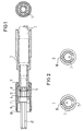
- a connector housing 3 is pushed over an incoming optical fiber cable 2, the connector 1 protruding from the front end thereof.
- This connector carries the optical fiber in a capillary in the center.
- the front end is ground together with the fiber optic fiber.
- the plug pin 1 is screwed securely to the plug housing 3 via a clamping ring 5.
- a longitudinally slotted sleeve 7 is pushed onto the front end of the plug pin and is compressed diagonally with respect to its slot 15 into a fold 16.
- the ring nut 4 has radial grooves 6 on the front in one of which the fold 16 engages in the axial direction. Only one of the radial grooves 6 is shown in FIG. 2.
- the longitudinally slotted sleeve 7 is inserted into that of the grooves 6, in which the greatest eccentricity of the fiber core 13 relative to the center 14 of that through corresponds to the knife line on which the fold 16 lies.
- This can also be done according to Principle II so that the fiber core 13 is opposite to Principle I on the other side opposite the center 14.
- Principle I or Principle II is set. Both options lead to the same result, namely a reduction in the attenuation of a plug connection by reducing the eccentricity of the two coupled fibers against one another. However, you have to commit to one of the two options.
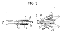
- FIG. 3 shows the centering sleeve 17 known per se, which in the example is surrounded by a slide-in holder 18. Since longitudinal slots 19 are provided on both ends of the holder 18 for the folds 16 of two plugs 1 to be brought together via the sleeve, the mutual position assignment of the plugs is given.
- the mating connector of the same or similar design to be inserted into the sleeve 17 from the right is no longer shown, but it basically consists of the same connector according to FIG. 1.
- a union nut 8 is provided, the internal thread 9 of which can be screwed onto the external thread 21 of the sleeve 18.
- a torque limit is provided on this union nut.
- a resilient, longitudinally slotted sleeve 12 is pushed over one of the bundles 10 or 11 of the union nut.
- This externally knurled tube 12 naturally has a slightly smaller inside diameter than the outside diameter knife corresponds to the union nut 8.
- the collars limit the axial play of this sleeve 12 and a friction clutch is created by the frictional torque between the parts 12 and 8, so that the tightening torque of the thread 9 is limited. In this way, an optically and mechanically effective optical fiber connector is created.
- FIG. 1 also shows a slight chamfer 20 of the plug pin 1, which allows air to escape when two such plugs are plugged together via the connecting sleeve 17, since these parts are mutually machined with a close fit.
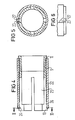
- the union nut in the region of the collar 24 is slotted longitudinally several times on a section 25 on the circumference.
- the slots 27 ensure that the union nut is feathered, that is to say springy in the radial direction, in this section.
- the sleeve Since the limitation of the torque is actually only required in the tightening direction, the sleeve is slit longitudinally at this end at a point on the circumference for a short distance, and the section 23, which lies in the tightening direction for the nut after the slot, is pressed in in a tongue-like manner. This creates a pawl effect, since this section slides over the segments of the spring in the tightening direction until the required tightening torque is reached. In the opposite direction, however, as shown by FIG. 5, the section 23 jumps into one of the slots 27, so that the full torque is transmitted from the sleeve 22 to the union nut 8 when the union nut is released, in the manner of a pawl. This ensures a safe loosening of the thread from the corresponding counter thread.
- the sleeve 22 is rigid, so that an increase in the torque is no longer possible by firmly gripping this part.
- the ratchet advantageously signals when the union nut is tightened that the required tightening torque has been reached.
Landscapes
- Physics & Mathematics (AREA)
- General Physics & Mathematics (AREA)
- Optics & Photonics (AREA)
- Mechanical Coupling Of Light Guides (AREA)
Applications Claiming Priority (4)
| Application Number | Priority Date | Filing Date | Title |
|---|---|---|---|
| DE8812341U | 1988-09-29 | ||
| DE8812341U DE8812341U1 (de) | 1988-09-29 | 1988-09-29 | Lichtwellenleiter-Stecker |
| DE8900623U | 1989-01-20 | ||
| DE8900623U DE8900623U1 (de) | 1989-01-20 | 1989-01-20 | Lichtwellenleiter-Stecker |
Publications (3)
| Publication Number | Publication Date |
|---|---|
| EP0361111A2 true EP0361111A2 (fr) | 1990-04-04 |
| EP0361111A3 EP0361111A3 (en) | 1990-10-17 |
| EP0361111B1 EP0361111B1 (fr) | 1994-04-20 |
Family
ID=25953589
Family Applications (1)
| Application Number | Title | Priority Date | Filing Date |
|---|---|---|---|
| EP89115840A Expired - Lifetime EP0361111B1 (fr) | 1988-09-29 | 1989-08-28 | Connexion embrochable pour des guides d'ondes lumineuses |
Country Status (4)
| Country | Link |
|---|---|
| US (1) | US5028114A (fr) |
| EP (1) | EP0361111B1 (fr) |
| JP (1) | JPH02125211A (fr) |
| DE (1) | DE58907498D1 (fr) |
Cited By (3)
| Publication number | Priority date | Publication date | Assignee | Title |
|---|---|---|---|---|
| AU620256B2 (en) * | 1989-06-28 | 1992-02-13 | Alcatel N.V. | Fibre optic connector |
| CH681329A5 (fr) * | 1991-02-11 | 1993-02-26 | Diamond Sa | |
| DE102018105682A1 (de) * | 2018-03-12 | 2019-09-12 | Aesculap Ag | Medizinische Mutter und Implantat |
Families Citing this family (69)
| Publication number | Priority date | Publication date | Assignee | Title |
|---|---|---|---|---|
| US5590228A (en) * | 1995-09-08 | 1996-12-31 | Packard Hughes Interconnect Company | Ratchet lock connector interlocking mechanism |
| US5619604A (en) * | 1996-02-26 | 1997-04-08 | Alcoa Fujikura Limited | Multi-fiber optical connector |
| US9239441B2 (en) | 2000-05-26 | 2016-01-19 | Corning Cable Systems Llc | Fiber optic drop cables and preconnectorized assemblies having toning portions |
| US6648520B2 (en) * | 2001-09-28 | 2003-11-18 | Corning Cable Systems Llc | Fiber optic plug |
| JP3483872B2 (ja) * | 2002-05-22 | 2004-01-06 | 米沢電線株式会社 | 光コネクタ |
| JP4774685B2 (ja) * | 2004-06-03 | 2011-09-14 | マツダ株式会社 | 動力伝達軸の支持構造 |
| US7568844B2 (en) * | 2006-08-15 | 2009-08-04 | Corning Cable Systems Llc | Ruggedized fiber optic connector assembly |
| US7787740B2 (en) * | 2008-06-12 | 2010-08-31 | Corning Cable Systems Llc | Universal cable bracket |
| US8452148B2 (en) | 2008-08-29 | 2013-05-28 | Corning Cable Systems Llc | Independently translatable modules and fiber optic equipment trays in fiber optic equipment |
| US11294136B2 (en) | 2008-08-29 | 2022-04-05 | Corning Optical Communications LLC | High density and bandwidth fiber optic apparatuses and related equipment and methods |
| US8272792B2 (en) * | 2008-09-30 | 2012-09-25 | Corning Cable Systems Llc | Retention bodies for fiber optic cable assemblies |
| US8303193B2 (en) * | 2008-09-30 | 2012-11-06 | Corning Cable Systems Llc | Retention bodies for fiber optic cable assemblies |
| US8285096B2 (en) | 2008-09-30 | 2012-10-09 | Corning Cable Systems Llc | Fiber optic cable assemblies and securing methods |
| ATE534049T1 (de) * | 2009-02-24 | 2011-12-15 | Ccs Technology Inc | Haltevorrichtung für ein kabel oder eine anordnung zur verwendung mit einem kabel |
| US8699838B2 (en) | 2009-05-14 | 2014-04-15 | Ccs Technology, Inc. | Fiber optic furcation module |
| US8538226B2 (en) | 2009-05-21 | 2013-09-17 | Corning Cable Systems Llc | Fiber optic equipment guides and rails configured with stopping position(s), and related equipment and methods |
| US9075216B2 (en) | 2009-05-21 | 2015-07-07 | Corning Cable Systems Llc | Fiber optic housings configured to accommodate fiber optic modules/cassettes and fiber optic panels, and related components and methods |
| US8712206B2 (en) | 2009-06-19 | 2014-04-29 | Corning Cable Systems Llc | High-density fiber optic modules and module housings and related equipment |
| CA2765830A1 (fr) * | 2009-06-19 | 2010-12-23 | Corning Cable Systems Llc | Appareil a densite elevee de compactage de cables a fibres optiques |
| WO2010148195A1 (fr) * | 2009-06-19 | 2010-12-23 | Corning Cable Systems Llc | Appareil d'infrastructure à connexion en fibre optique haute capacité |
| WO2010148336A1 (fr) | 2009-06-19 | 2010-12-23 | Corning Cable Systems Llc | Appareils à fibres optiques à large bande et à densité élevée et équipement et procédés associés |
| EP2446312A1 (fr) * | 2009-06-22 | 2012-05-02 | Corning Cable Systems LLC | Dispositif de positionnement de câble à fibre optique |
| US20110044584A1 (en) * | 2009-08-19 | 2011-02-24 | Diba Industries, Inc. | Optical fiber connection assembly |
| US8625950B2 (en) * | 2009-12-18 | 2014-01-07 | Corning Cable Systems Llc | Rotary locking apparatus for fiber optic equipment trays and related methods |
| US8593828B2 (en) | 2010-02-04 | 2013-11-26 | Corning Cable Systems Llc | Communications equipment housings, assemblies, and related alignment features and methods |
| US8913866B2 (en) * | 2010-03-26 | 2014-12-16 | Corning Cable Systems Llc | Movable adapter panel |
| AU2011265751B2 (en) | 2010-04-16 | 2015-09-10 | Corning Optical Communications LLC | Sealing and strain relief device for data cables |
| EP2381284B1 (fr) | 2010-04-23 | 2014-12-31 | CCS Technology Inc. | Dispositif de distribution à fibre optique encastré dans le sol |
| US9632270B2 (en) | 2010-04-30 | 2017-04-25 | Corning Optical Communications LLC | Fiber optic housings configured for tool-less assembly, and related components and methods |
| US9720195B2 (en) | 2010-04-30 | 2017-08-01 | Corning Optical Communications LLC | Apparatuses and related components and methods for attachment and release of fiber optic housings to and from an equipment rack |
| US8705926B2 (en) | 2010-04-30 | 2014-04-22 | Corning Optical Communications LLC | Fiber optic housings having a removable top, and related components and methods |
| US8660397B2 (en) | 2010-04-30 | 2014-02-25 | Corning Cable Systems Llc | Multi-layer module |
| US8879881B2 (en) | 2010-04-30 | 2014-11-04 | Corning Cable Systems Llc | Rotatable routing guide and assembly |
| US9075217B2 (en) | 2010-04-30 | 2015-07-07 | Corning Cable Systems Llc | Apparatuses and related components and methods for expanding capacity of fiber optic housings |
| US9519118B2 (en) | 2010-04-30 | 2016-12-13 | Corning Optical Communications LLC | Removable fiber management sections for fiber optic housings, and related components and methods |
| US8718436B2 (en) | 2010-08-30 | 2014-05-06 | Corning Cable Systems Llc | Methods, apparatuses for providing secure fiber optic connections |
| US9279951B2 (en) | 2010-10-27 | 2016-03-08 | Corning Cable Systems Llc | Fiber optic module for limited space applications having a partially sealed module sub-assembly |
| US8662760B2 (en) | 2010-10-29 | 2014-03-04 | Corning Cable Systems Llc | Fiber optic connector employing optical fiber guide member |
| US9116324B2 (en) | 2010-10-29 | 2015-08-25 | Corning Cable Systems Llc | Stacked fiber optic modules and fiber optic equipment configured to support stacked fiber optic modules |
| CA2819235C (fr) | 2010-11-30 | 2018-01-16 | Corning Cable Systems Llc | Support de corps de fibre et dispositif de reduction des tensions |
| WO2012106510A2 (fr) | 2011-02-02 | 2012-08-09 | Corning Cable Systems Llc | Ensembles de connecteurs de fibres optiques denses et connecteurs associés et câbles appropriés pour établir des connexions optiques pour des fonds de panier optiques dans des râteliers d'équipement |
| DE102011001080B4 (de) * | 2011-03-03 | 2013-09-12 | Phoenix Contact Gmbh & Co. Kg | Steckverbinder mit einer Lösesicherung |
| US9008485B2 (en) | 2011-05-09 | 2015-04-14 | Corning Cable Systems Llc | Attachment mechanisms employed to attach a rear housing section to a fiber optic housing, and related assemblies and methods |
| WO2013003303A1 (fr) | 2011-06-30 | 2013-01-03 | Corning Cable Systems Llc | Ensembles d'équipement à fibres optiques utilisant des boîtiers hors dimensions de largeur u, et procédés associés |
| US8953924B2 (en) | 2011-09-02 | 2015-02-10 | Corning Cable Systems Llc | Removable strain relief brackets for securing fiber optic cables and/or optical fibers to fiber optic equipment, and related assemblies and methods |
| US9038832B2 (en) | 2011-11-30 | 2015-05-26 | Corning Cable Systems Llc | Adapter panel support assembly |
| US8939655B2 (en) | 2012-06-29 | 2015-01-27 | Corning Cable Systems Llc | Dust caps, fiber optic connectors, and fiber optic splitter modules incorporating interlocking key features |
| US9250409B2 (en) | 2012-07-02 | 2016-02-02 | Corning Cable Systems Llc | Fiber-optic-module trays and drawers for fiber-optic equipment |
| US9042702B2 (en) | 2012-09-18 | 2015-05-26 | Corning Cable Systems Llc | Platforms and systems for fiber optic cable attachment |
| ES2551077T3 (es) | 2012-10-26 | 2015-11-16 | Ccs Technology, Inc. | Unidad de gestión de fibra óptica y dispositivo de distribución de fibra óptica |
| US8985862B2 (en) | 2013-02-28 | 2015-03-24 | Corning Cable Systems Llc | High-density multi-fiber adapter housings |
| US9052469B2 (en) | 2013-04-26 | 2015-06-09 | Corning Cable Systems Llc | Preterminated fiber optic connector sub-assemblies, and related fiber optic connectors, cable assemblies, and methods |
| US11668890B2 (en) | 2017-06-28 | 2023-06-06 | Corning Research & Development Corporation | Multiports and other devices having optical connection ports with securing features and methods of making the same |
| US11187859B2 (en) | 2017-06-28 | 2021-11-30 | Corning Research & Development Corporation | Fiber optic connectors and methods of making the same |
| EP3646092B1 (fr) | 2017-06-28 | 2021-11-24 | Corning Research & Development Corporation | Connecteurs de fibres optiques compacts |
| US12271040B2 (en) | 2017-06-28 | 2025-04-08 | Corning Research & Development Corporation | Fiber optic extender ports, assemblies and methods of making the same |
| US10359577B2 (en) | 2017-06-28 | 2019-07-23 | Corning Research & Development Corporation | Multiports and optical connectors with rotationally discrete locking and keying features |
| MX2021006211A (es) | 2018-11-29 | 2021-08-11 | Corning Res & Dev Corp | Multipuertos y otros dispositivos que tienen puertos de conexion optica con accionadores giratorios y metodos de fabricacion de los mismos. |
| MX2021014427A (es) | 2019-05-31 | 2022-03-04 | Corning Res & Dev Corp | Multipuertos y otros dispositivos que tienen puertos de conexion optica con accionadores deslizantes y metodos para elaborar los mismos. |
| US11294133B2 (en) | 2019-07-31 | 2022-04-05 | Corning Research & Development Corporation | Fiber optic networks using multiports and cable assemblies with cable-to-connector orientation |
| EP4045957B1 (fr) | 2019-10-18 | 2023-12-13 | Corning Research & Development Corporation | Multiports ayant des ports de connexion optiques avec des éléments de fixation fournissant des forces de retenue stables |
| US11536921B2 (en) | 2020-02-11 | 2022-12-27 | Corning Research & Development Corporation | Fiber optic terminals having one or more loopback assemblies |
| CA3184578A1 (fr) | 2020-06-29 | 2022-01-06 | Michael De Jong | Bornes ayant un orifice de connexion optique multifibre qui empeche un endommagement a partir de connecteurs a monofibre |
| US11604320B2 (en) | 2020-09-30 | 2023-03-14 | Corning Research & Development Corporation | Connector assemblies for telecommunication enclosures |
| CN116601834A (zh) | 2020-10-30 | 2023-08-15 | 康宁研究与开发公司 | 具有防风雨套环的光纤连接器 |
| US11927810B2 (en) | 2020-11-30 | 2024-03-12 | Corning Research & Development Corporation | Fiber optic adapter assemblies including a conversion housing and a release member |
| US11994722B2 (en) | 2020-11-30 | 2024-05-28 | Corning Research & Development Corporation | Fiber optic adapter assemblies including an adapter housing and a locking housing |
| US11686913B2 (en) | 2020-11-30 | 2023-06-27 | Corning Research & Development Corporation | Fiber optic cable assemblies and connector assemblies having a crimp ring and crimp body and methods of fabricating the same |
| US11880076B2 (en) | 2020-11-30 | 2024-01-23 | Corning Research & Development Corporation | Fiber optic adapter assemblies including a conversion housing and a release housing |
Family Cites Families (13)
| Publication number | Priority date | Publication date | Assignee | Title |
|---|---|---|---|---|
| US4279469A (en) * | 1975-05-27 | 1981-07-21 | The United States Of America As Represented By The Secretary Of The Navy | Separable fiber optic cable connector |
| US4008948A (en) * | 1975-06-30 | 1977-02-22 | Northern Telecom Limited | Optical fibre connectors |
| FR2512216A1 (fr) * | 1981-08-26 | 1983-03-04 | Cables De Lyon Geoffroy Delore | Dispositif de connexion pour cable comprenant des fibres optiques et des conducteurs metalliques |
| FR2528984A1 (fr) * | 1982-06-22 | 1983-12-23 | Socapex | Fiche pour connecteur de fibres optiques et connecteur la comportant |
| US4687292A (en) * | 1984-04-18 | 1987-08-18 | Siemens Aktiengesellschaft | Light waveguide plug connector |
| JPH0627884B2 (ja) * | 1984-07-20 | 1994-04-13 | 日本電気株式会社 | 光コネクタ |
| JPS6199110A (ja) * | 1984-10-03 | 1986-05-17 | Fuji Electric Co Ltd | 光フアイバコネクタ |
| JPH063488B2 (ja) * | 1984-11-28 | 1994-01-12 | 富士通株式会社 | 光コネクタ |
| US4738508A (en) * | 1985-06-28 | 1988-04-19 | American Telephone And Telegraph Company, At&T Technologies, Inc. | Terminated optical fiber and methods of making |
| US4749251A (en) * | 1985-07-11 | 1988-06-07 | Hughes Aircraft Company | Connector locking system |
| US4705352A (en) * | 1985-12-30 | 1987-11-10 | Amphenol Corporation | Fiber optic connector |
| JPS6336210A (ja) * | 1986-07-29 | 1988-02-16 | ジ−メンス・アクチエンゲゼルシヤフト | 光波導体差込み結合部材を備えた装置 |
| JPS6341811A (ja) * | 1986-08-08 | 1988-02-23 | Fujitsu Ltd | 光コネクタ位置決め構造 |
-
1989
- 1989-08-21 US US07/395,998 patent/US5028114A/en not_active Expired - Fee Related
- 1989-08-28 EP EP89115840A patent/EP0361111B1/fr not_active Expired - Lifetime
- 1989-08-28 DE DE58907498T patent/DE58907498D1/de not_active Expired - Fee Related
- 1989-09-29 JP JP1252486A patent/JPH02125211A/ja active Granted
Cited By (4)
| Publication number | Priority date | Publication date | Assignee | Title |
|---|---|---|---|---|
| AU620256B2 (en) * | 1989-06-28 | 1992-02-13 | Alcatel N.V. | Fibre optic connector |
| CH681329A5 (fr) * | 1991-02-11 | 1993-02-26 | Diamond Sa | |
| DE102018105682A1 (de) * | 2018-03-12 | 2019-09-12 | Aesculap Ag | Medizinische Mutter und Implantat |
| WO2019175136A1 (fr) | 2018-03-12 | 2019-09-19 | Aesculap Ag | Implant |
Also Published As
| Publication number | Publication date |
|---|---|
| JPH02125211A (ja) | 1990-05-14 |
| EP0361111B1 (fr) | 1994-04-20 |
| JPH0578006B2 (fr) | 1993-10-27 |
| EP0361111A3 (en) | 1990-10-17 |
| US5028114A (en) | 1991-07-02 |
| DE58907498D1 (de) | 1994-05-26 |
Similar Documents
| Publication | Publication Date | Title |
|---|---|---|
| EP0361111B1 (fr) | Connexion embrochable pour des guides d'ondes lumineuses | |
| DE2558445C2 (de) | Verbindereinheit für eine Faseroptik und Verfahren zum Endanschließen einer Faseroptik | |
| DE3851178T2 (de) | Stecker für faseroptischen Kabelverbinder. | |
| EP0164531B1 (fr) | Connecteur à fiches pour guides d'ondes lumineuses | |
| DE69806150T2 (de) | Optischer faser stecker | |
| DE69914542T2 (de) | Einstellbares optisches Dämpfungsglied mit Verriegelungsratsche | |
| EP0345519B1 (fr) | Connecteur à fiches en deux pièces pour guides d'ondes lumineuses | |
| DE3124546C2 (fr) | ||
| DE3010395A1 (de) | Verbindungselement fuer optische leitungen | |
| DE69328958T2 (de) | Faseroptische Justiervorrichtung | |
| DE3517388A1 (de) | Anschlussteil fuer ein faser-optisches kabel | |
| EP1478959A1 (fr) | Raccord optique enfichable | |
| DE2846774A1 (de) | Loesbare steckverbindung sowie stecker und zwischenteil zum kuppeln einer lichtleitungsfaser an eine weitere lichtleitungsfaser oder an eine lichtquelle bzw. einen lichtdetektor | |
| DE2824507C2 (de) | Steckvorrichtung zur elektromagnetischen Kopplung von optischen Faserleitern | |
| DE2923490C2 (de) | Stecker für Lichtleitungsverbinder | |
| CH681329A5 (fr) | ||
| EP0961942B1 (fr) | Connecteur a fiches pour guide d'ondes lumineuses | |
| EP0176820A2 (fr) | Elément d'un connecteur pour des connexions séparables des guides d'ondes lumineuses | |
| EP0312147A2 (fr) | Capuchon de protection montable sur une fiche ou sur le couplage d'un connecteur pour guide d'onde lumineuse | |
| CH682848A5 (de) | LWL-Stecker mit federndem Steckerstift. | |
| EP0463404B1 (fr) | Connecteur pour fibres optiques | |
| EP0373340B1 (fr) | Connecteur démontable pour le couplage de deux fibres optiques | |
| DE8812341U1 (de) | Lichtwellenleiter-Stecker | |
| DE2527008C3 (de) | Mehrfachsteckvorrichtung für Einzellichtwellenleiter | |
| DE69102613T2 (de) | Optisches verbindungssystem zur anwendung in der übertragung von video-signalen. |
Legal Events
| Date | Code | Title | Description |
|---|---|---|---|
| PUAI | Public reference made under article 153(3) epc to a published international application that has entered the european phase |
Free format text: ORIGINAL CODE: 0009012 |
|
| AK | Designated contracting states |
Kind code of ref document: A2 Designated state(s): BE DE GB GR IT |
|
| PUAL | Search report despatched |
Free format text: ORIGINAL CODE: 0009013 |
|
| AK | Designated contracting states |
Kind code of ref document: A3 Designated state(s): BE DE GB GR IT |
|
| 17P | Request for examination filed |
Effective date: 19901219 |
|
| 17Q | First examination report despatched |
Effective date: 19920812 |
|
| GRAA | (expected) grant |
Free format text: ORIGINAL CODE: 0009210 |
|
| AK | Designated contracting states |
Kind code of ref document: B1 Designated state(s): BE DE GB GR IT |
|
| REF | Corresponds to: |
Ref document number: 58907498 Country of ref document: DE Date of ref document: 19940526 |
|
| ITF | It: translation for a ep patent filed | ||
| PGFP | Annual fee paid to national office [announced via postgrant information from national office to epo] |
Ref country code: GB Payment date: 19940718 Year of fee payment: 6 |
|
| GBT | Gb: translation of ep patent filed (gb section 77(6)(a)/1977) |
Effective date: 19940627 |
|
| PGFP | Annual fee paid to national office [announced via postgrant information from national office to epo] |
Ref country code: BE Payment date: 19940818 Year of fee payment: 6 |
|
| PGFP | Annual fee paid to national office [announced via postgrant information from national office to epo] |
Ref country code: GR Payment date: 19940826 Year of fee payment: 6 |
|
| REG | Reference to a national code |
Ref country code: GR Ref legal event code: FG4A Free format text: 3012425 |
|
| PLBE | No opposition filed within time limit |
Free format text: ORIGINAL CODE: 0009261 |
|
| STAA | Information on the status of an ep patent application or granted ep patent |
Free format text: STATUS: NO OPPOSITION FILED WITHIN TIME LIMIT |
|
| 26N | No opposition filed | ||
| PG25 | Lapsed in a contracting state [announced via postgrant information from national office to epo] |
Ref country code: DE Effective date: 19950503 |
|
| PG25 | Lapsed in a contracting state [announced via postgrant information from national office to epo] |
Ref country code: GB Effective date: 19950828 |
|
| PG25 | Lapsed in a contracting state [announced via postgrant information from national office to epo] |
Ref country code: BE Effective date: 19950831 |
|
| PG25 | Lapsed in a contracting state [announced via postgrant information from national office to epo] |
Ref country code: GR Free format text: THE PATENT HAS BEEN ANNULLED BY A DECISION OF A NATIONAL AUTHORITY Effective date: 19960228 |
|
| BERE | Be: lapsed |
Owner name: SIEMENS A.G. Effective date: 19950831 |
|
| GBPC | Gb: european patent ceased through non-payment of renewal fee |
Effective date: 19950828 |
|
| REG | Reference to a national code |
Ref country code: GR Ref legal event code: MM2A Free format text: 3012425 |
|
| PG25 | Lapsed in a contracting state [announced via postgrant information from national office to epo] |
Ref country code: IT Free format text: LAPSE BECAUSE OF NON-PAYMENT OF DUE FEES;WARNING: LAPSES OF ITALIAN PATENTS WITH EFFECTIVE DATE BEFORE 2007 MAY HAVE OCCURRED AT ANY TIME BEFORE 2007. THE CORRECT EFFECTIVE DATE MAY BE DIFFERENT FROM THE ONE RECORDED. Effective date: 20050828 |