EP0361134A2 - Distributeur combiné échangeable de gaz frais pour dispositif d'anesthésie - Google Patents
Distributeur combiné échangeable de gaz frais pour dispositif d'anesthésie Download PDFInfo
- Publication number
- EP0361134A2 EP0361134A2 EP89116291A EP89116291A EP0361134A2 EP 0361134 A2 EP0361134 A2 EP 0361134A2 EP 89116291 A EP89116291 A EP 89116291A EP 89116291 A EP89116291 A EP 89116291A EP 0361134 A2 EP0361134 A2 EP 0361134A2
- Authority
- EP
- European Patent Office
- Prior art keywords
- anesthetic
- fresh gas
- delivery unit
- gas delivery
- flow
- Prior art date
- Legal status (The legal status is an assumption and is not a legal conclusion. Google has not performed a legal analysis and makes no representation as to the accuracy of the status listed.)
- Withdrawn
Links
Images
Classifications
-
- A—HUMAN NECESSITIES
- A61—MEDICAL OR VETERINARY SCIENCE; HYGIENE
- A61M—DEVICES FOR INTRODUCING MEDIA INTO, OR ONTO, THE BODY; DEVICES FOR TRANSDUCING BODY MEDIA OR FOR TAKING MEDIA FROM THE BODY; DEVICES FOR PRODUCING OR ENDING SLEEP OR STUPOR
- A61M16/00—Devices for influencing the respiratory system of patients by gas treatment, e.g. ventilators; Tracheal tubes
- A61M16/10—Preparation of respiratory gases or vapours
- A61M16/104—Preparation of respiratory gases or vapours specially adapted for anaesthetics
-
- A—HUMAN NECESSITIES
- A61—MEDICAL OR VETERINARY SCIENCE; HYGIENE
- A61M—DEVICES FOR INTRODUCING MEDIA INTO, OR ONTO, THE BODY; DEVICES FOR TRANSDUCING BODY MEDIA OR FOR TAKING MEDIA FROM THE BODY; DEVICES FOR PRODUCING OR ENDING SLEEP OR STUPOR
- A61M16/00—Devices for influencing the respiratory system of patients by gas treatment, e.g. ventilators; Tracheal tubes
- A61M16/10—Preparation of respiratory gases or vapours
- A61M16/1005—Preparation of respiratory gases or vapours with O2 features or with parameter measurement
- A61M16/1015—Preparation of respiratory gases or vapours with O2 features or with parameter measurement using a gas flush valve, e.g. oxygen flush valve
-
- A—HUMAN NECESSITIES
- A61—MEDICAL OR VETERINARY SCIENCE; HYGIENE
- A61M—DEVICES FOR INTRODUCING MEDIA INTO, OR ONTO, THE BODY; DEVICES FOR TRANSDUCING BODY MEDIA OR FOR TAKING MEDIA FROM THE BODY; DEVICES FOR PRODUCING OR ENDING SLEEP OR STUPOR
- A61M16/00—Devices for influencing the respiratory system of patients by gas treatment, e.g. ventilators; Tracheal tubes
- A61M16/10—Preparation of respiratory gases or vapours
- A61M16/14—Preparation of respiratory gases or vapours by mixing different fluids, one of them being in a liquid phase
- A61M16/18—Vaporising devices for anaesthetic preparations
-
- A—HUMAN NECESSITIES
- A61—MEDICAL OR VETERINARY SCIENCE; HYGIENE
- A61M—DEVICES FOR INTRODUCING MEDIA INTO, OR ONTO, THE BODY; DEVICES FOR TRANSDUCING BODY MEDIA OR FOR TAKING MEDIA FROM THE BODY; DEVICES FOR PRODUCING OR ENDING SLEEP OR STUPOR
- A61M16/00—Devices for influencing the respiratory system of patients by gas treatment, e.g. ventilators; Tracheal tubes
- A61M16/10—Preparation of respiratory gases or vapours
- A61M16/105—Filters
- A61M16/106—Filters in a path
- A61M16/107—Filters in a path in the inspiratory path
-
- A—HUMAN NECESSITIES
- A61—MEDICAL OR VETERINARY SCIENCE; HYGIENE
- A61M—DEVICES FOR INTRODUCING MEDIA INTO, OR ONTO, THE BODY; DEVICES FOR TRANSDUCING BODY MEDIA OR FOR TAKING MEDIA FROM THE BODY; DEVICES FOR PRODUCING OR ENDING SLEEP OR STUPOR
- A61M16/00—Devices for influencing the respiratory system of patients by gas treatment, e.g. ventilators; Tracheal tubes
- A61M16/0003—Accessories therefor, e.g. sensors, vibrators, negative pressure
- A61M2016/003—Accessories therefor, e.g. sensors, vibrators, negative pressure with a flowmeter
- A61M2016/0033—Accessories therefor, e.g. sensors, vibrators, negative pressure with a flowmeter electrical
- A61M2016/0039—Accessories therefor, e.g. sensors, vibrators, negative pressure with a flowmeter electrical in the inspiratory circuit
Definitions
- the invention relates to a combined, replaceable fresh gas delivery unit for anesthesia devices.
- these and any other non-essential components are merely mechanically and pneumatically connected to each other, so that with increasing number of individual components, the risk of mix-ups and leaks increases by leaps and bounds.
- Another disadvantage of the fresh gas delivery units according to the prior art lies in the fact that the oxygen concentration and the entire gas flow cannot be changed independently of one another to meet the respective requirements, so that the anesthetist himself can calculate the oxygen concentration after each readjustment and, using an iterative process, a desired one Must approximate value.
- the rotameters used in conventional fresh gas dispensing units for dosing the anesthetic gases are very inaccurate - especially in the lower measuring range - the lack of international standardization can always lead to confusion with fatal results.
- the evaporators used as individual components can also be filled with the wrong anesthetic, which can also have fatal consequences.
- the thymol used as a stabilizer for the anesthetic in the evaporators which work on the principle of an evaporator, can also lead to blockages and thus to considerable errors.
- the accuracy of conventional vaporizers is very questionable, since the delivery of the anesthetic depends on many uncontrollable factors (ambient temperature, ambient pressure, concentration of the anesthetic gases that act as carriers, solubility of the laughing gas in the anesthetic).
- the invention seeks to remedy this.
- the object of the invention is to create a fresh gas dispensing unit for anesthesia devices that functions as a unit, which, on the one hand, is combined and can therefore be exchanged for any anesthesia device, and on the other hand, all functions can be controlled and monitored centrally.
- Another task is the improved admixture of the anesthetic to the gas mixture.
- the invention achieves the stated object with a combined, exchangeable fresh gas delivery unit which has the features of claim 1.
- the following advantages result: - Thanks to the central control, the oxygen concentration and the entire gas flow can be set using two independent controllers. The tedious iterative process is eliminated. - A high accuracy of ⁇ 2 vol% oxygen can be achieved over the entire flow range (0.2 to 15 l / min). - The oxygen concentration remains constant even when changing the evaporator. - The occurrence of a hypoxic gas mixture is automatically prevented. - In the event of an oxygen pressure drop, the system automatically switches to air operation. - In the event of dangerous alarm conditions, an oxygen flush is triggered automatically. - The oxygen concentration is independent of the environmental parameters. - The anesthetic content can be dosed very precisely over the entire flow range (0.2 to 15 l / min).
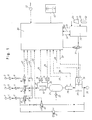
- the gas inlets 1, 2, 3 are the interfaces between the anesthesia machine and the gas supply system or the gas bottles of the hospital. Oxygen 1 and nitrous oxide 2 are normally used for anesthesia. But there can be more Gas inlets, such as for compressed air 3, carbon dioxide, helium, etc. are used. The inlet pressure is typically 3.5 bar.
- Filters 4, 5, 6 are connected downstream of the gas inlets 1, 2 and 3 and are intended to prevent the flow of foreign, in particular solid, particles that could come from the gas inlets 1, 2, 3. This ensures that only clean gases reach the patient. Downstream of the filters 4,5,6 are one-way valves 7,8,9, which are to ensure that the gas flow can only take place in one direction. This prevents any back mixing of the gases.
- gas valves 10, 11, 12 Downstream of the one-way valves 7, 8, 9 are gas valves 10, 11, 12 (oxygen valve 10, nitrous oxide valve 11 and compressed air valve 12), which are electrically operated.
- the oxygen valve is connected to the electronic control unit 20 via the oxygen valve control line 44, the nitrous oxide valve 11 via the nitrous oxide valve control line 45 and the compressed air valve 12 via the compressed air valve control line 47. If there is an electrical voltage, the corresponding valve switches through and a gas flow can flow through.
- the measuring orifice 16 is a laminar orifice in which a pressure drop which is proportional to the gas flow occurs.
- the lines 17 and 23 lead from the measuring orifice 16 to the flow pressure converter 18, which converts the differential pressure drop measured by means of the measuring orifice 16 into an electrical signal 19 which is proportional to the flow and which is supplied to the electronic control unit 20.
- the gases flowing through the laminar diaphragm 16 are fed to a storage container 21 with a predetermined volume, which stores the incoming gases for a certain time and permits their mixing.
- the mixed gases in the storage container 21 are typically under a pressure of 200-1000 mbar.
- an overpressure valve 22 limits the maximum pressure in the storage container 21 to a predetermined value.
- the setting is typically 1.2 bar.
- a container pressure measuring transducer 24 connected to the storage container 21 via the line 23 converts the measured pressure in the storage container 21 into an electrical signal 25 which is fed to the electronic control unit 20.
- a flow control valve 26 connected downstream of the storage container 21 (for example a servo valve or mass flow controller) generates a continuous gas flow out of the storage container 21, which functions in relation to the electrical setpoint 27 for the flow. The actual flow is detected by the flow measurement signal line 28, which leads to the electronic control unit 20.
- Anesthetic containers 29, 30 or others in the form of bottles or recipients contain the volatile anesthetic 31, 32 which is present in the liquid state. If different anesthetics 31, 32 are used, one or more anesthetic containers 29, 30 can be connected.
- a liquid metering device 33 (for example a controlled syringe or pump) takes a predetermined amount of liquid anesthetic 31, 32 from the anesthetic container 29, 30 and conveys it further to a safety valve 35. The amount to be metered is specified via the liquid set point line 34.
- the safety valve 35 prevents liquid 31, 32 from being conveyed further in the switched-off state or in the event of a malfunction of the fresh gas delivery unit.
- An evaporation unit 36 converts the metered liquid 31, 32 into the vaporous state by means of electrical energy supplied via the line 48. The energy required for this is a measure of the amount of liquid evaporated.
- the temperature of the evaporation unit 36 is kept constant and recorded via the temperature measurement signal 37 and supplied to the electronic control unit 20.
- the mixing of the vaporous anesthetic supplied by the evaporation unit 36 with the gas flow regulated by the flow control valve 26 from the storage container 21 takes place in a mixing chamber 38.
- the fresh gas prepared in the mixing chamber 38 passes through an outlet 39 to the patient hose system (not shown).
- an emergency valve 40 automatically ensures an oxygen flow to the outlet 39 and thus to the patient.
- This emergency valve 40 is activated by the electronic control unit 20 via the line emergency valve control 46.
- the user Via a flush valve 41, the user has the option of having a predetermined high oxygen gas flow (typically 40 liters / min) flow to the patient hose system and thus to the patient.
- This flush valve 41 is operated directly by the user.
- the electronic control unit 20 regulates and controls the entire sequence of gas mixing, gas flow metering and anesthetic admixture. Based on the parameters desired by the user, e.g. the desired gas concentration, the desired flow and the desired anesthetic concentration, the corresponding assemblies, units and components of the device according to the invention are controlled and / or regulated.
- a mains power supply 42 has the task of supplying the electronics and the corresponding assemblies with electrical energy.
- a battery power supply 43 ensures that the entire device remains functional for a certain time in the event of a power failure or a missing mains power supply 42.
- the gas mixture (for example oxygen / nitrous oxide; oxygen / air or other combinations) is located in the storage container 21 under a certain maximum pressure of, for example, 1000 mbar.
- the flow control valve 26 continuously extracts a constant gas flow of, for example, 1 liter / minute from the storage container 21. As a result, the pressure in the storage container 21 drops. As soon as the pressure reaches a minimum value of, for example, 200 mbar, this is detected by the electronic control unit 20 via the container pressure sensor 24 and the line container pressure measurement signal 25. After the detection of the minimum pressure limit, the electronic control unit 20 starts the loading process of the storage container 21.
- the electronic control unit 20 now calculates the necessary total volume, which must flow back into the storage container 21 in order to increase the desired maximum container pressure, based on the existing minimum pressure, the desired maximum container pressure, the outflow via the flow control valve 26 and the geometric dimensions of the storage container 21 to reach.
- the electronic control unit 20 calculates the partial volumes for oxygen and nitrous oxide (for an oxygen / Nitrous oxide mixture).
- the electronic control unit 20 now switches the oxygen valve 10 through via the oxygen valve control line 44 until the integral over the time of the flow measurement signal 19 (measured oxygen volume delivered) gives the value of the calculated partial volume for the oxygen. After the partial oxygen volume is reached, the electronic control unit 20 switches off the oxygen valve 10. The oxygen gas flow to the reservoir 21 is thus interrupted.
- the electronic control unit 20 now switches the laughing gas valve 11 through the laughing gas control line 45 until the integral over the time of the flow measurement signal 19 (measured delivered laughing gas volume) gives the value of the calculated partial volume for the laughing gas. When the laughing gas partial volume is reached, the electronic control unit 20 switches off the laughing gas valve 11.
- the nitrous oxide flow to the storage container 21 is thus interrupted and the desired maximum container pressure (eg 1000 mbar) prevails again in the storage container 21.
- the reservoir pressure now begins to drop again and as soon as the minimum pressure is reached, the charging process is started again by the electronic control unit 20. Thanks to the use of the same measuring aperture 16 for determining the Partial volumes of oxygen and nitrous oxide achieve a high concentration accuracy because any inaccuracies in the measuring orifice 16 and the flow pressure converter 18 compensate each other.
- the electronic control unit 20 sends a corresponding electrical signal to the flow control valve 26 via the flow setpoint 27 line.
- the size of the signal depends on the set total flow (e.g. 1 liter / min).
- the flow control valve 26 is now adjusted until the flow measurement signal transmitted via line 28 corresponds to the flow setpoint signal transmitted via line 27.
- the electronic control unit 20 specifies a specific setpoint via the liquid setpoint 34 line to the liquid metering unit 33.
- the liquid metering unit 33 takes the necessary amount of anesthetic 31 or 32 from the anesthetic container 29, 30, reports the amount withdrawn via the liquid actual value line 50 to the electronic control unit 20 and conveys this amount to the evaporation unit 36 via a safety valve 35.
- the energy that is needed around the temperature keeping the evaporation unit 36 constant depends on the amount of liquid supplied. This allows the amount of liquid evaporated to be monitored.
- the electronic control unit 20 switches off the safety valve 35 and the liquid supply to the evaporation unit 36 is interrupted immediately.
- the user has the option of using different anesthetics 31, 32 or more. Either he selects the desired anesthetic 31, 32 via the electronic control unit 20 and the liquid metering unit 33 then takes the necessary amount of liquid from the corresponding container 29 or 30 or he can specify the desired anesthetic 31 or 32 by deliberately plugging in the anesthetic container 29 or 30. In the latter case, the liquid metering unit 33 detects which anesthetic 31 or 32 is in use and passes this information on to the electronic control unit 20 via the line 49.
- the electronic control unit 20 consists either of one or more conventional microcontrollers integrated in the fresh gas discharge unit or a separate computer, for example a personal computer.
- the input variables can either be fed in directly by the user via suitable potentiometers, buttons or via a standardized interface from another device, for example a computer.
Landscapes
- Health & Medical Sciences (AREA)
- Anesthesiology (AREA)
- Emergency Medicine (AREA)
- Life Sciences & Earth Sciences (AREA)
- Engineering & Computer Science (AREA)
- Biomedical Technology (AREA)
- Heart & Thoracic Surgery (AREA)
- Hematology (AREA)
- Pulmonology (AREA)
- Animal Behavior & Ethology (AREA)
- General Health & Medical Sciences (AREA)
- Public Health (AREA)
- Veterinary Medicine (AREA)
- Acyclic And Carbocyclic Compounds In Medicinal Compositions (AREA)
- Feeding, Discharge, Calcimining, Fusing, And Gas-Generation Devices (AREA)
- Respiratory Apparatuses And Protective Means (AREA)
Applications Claiming Priority (2)
| Application Number | Priority Date | Filing Date | Title |
|---|---|---|---|
| CH3570/88 | 1988-09-27 | ||
| CH3570/88A CH676203A5 (fr) | 1988-09-27 | 1988-09-27 |
Publications (2)
| Publication Number | Publication Date |
|---|---|
| EP0361134A2 true EP0361134A2 (fr) | 1990-04-04 |
| EP0361134A3 EP0361134A3 (fr) | 1990-10-10 |
Family
ID=4258845
Family Applications (1)
| Application Number | Title | Priority Date | Filing Date |
|---|---|---|---|
| EP19890116291 Withdrawn EP0361134A3 (fr) | 1988-09-27 | 1989-09-04 | Distributeur combiné échangeable de gaz frais pour dispositif d'anesthésie |
Country Status (3)
| Country | Link |
|---|---|
| EP (1) | EP0361134A3 (fr) |
| JP (1) | JPH02134162A (fr) |
| CH (1) | CH676203A5 (fr) |
Cited By (9)
| Publication number | Priority date | Publication date | Assignee | Title |
|---|---|---|---|---|
| US5052382A (en) * | 1988-04-29 | 1991-10-01 | Wainwright Basil E | Apparatus for the controlled generation and administration of ozone |
| EP0566488A1 (fr) * | 1992-04-15 | 1993-10-20 | Taema | Procédé et dispositif d'élaboration d'un mélange gazeux anesthésique |
| US5272907A (en) * | 1990-06-08 | 1993-12-28 | Instrumentarium Corporation | Method for the identification of gases |
| EP0685238A3 (fr) * | 1994-05-06 | 1996-02-28 | Instrumentarium Oy | Mélangeur de gaz. |
| US5649531A (en) * | 1991-11-15 | 1997-07-22 | Instrumentarium Corporation | Method and apparatus for metering an anaesthetic to a patient |
| US6024087A (en) * | 1997-10-09 | 2000-02-15 | Ohmeda Inc. | Emergency oxygen flowmeter arrangement |
| FR2805468A1 (fr) * | 2000-02-26 | 2001-08-31 | Drager Medizintechnik Gmbh | Dispositif doseur de gaz pour systeme d'assistance respiratoire |
| CN111973852A (zh) * | 2020-08-10 | 2020-11-24 | 深圳市普博科技有限公司 | 麻醉剂的输出浓度控制方法、装置、设备及存储介质 |
| EP4164718A4 (fr) * | 2020-06-11 | 2024-06-12 | Hu-Friedy Mfg. Co., LLC | Vérification de ligne d'oxygène pour des commandes de flux de gaz d'anesthésie |
Families Citing this family (3)
| Publication number | Priority date | Publication date | Assignee | Title |
|---|---|---|---|---|
| JP3175138B2 (ja) * | 1994-11-22 | 2001-06-11 | 横河電機株式会社 | バスインターフェイス装置 |
| JP2011083472A (ja) * | 2009-10-16 | 2011-04-28 | Murako Medical:Kk | 液体麻酔剤気化装置 |
| CN103285483B (zh) * | 2013-06-05 | 2015-07-22 | 深圳市瑞沃德生命科技有限公司 | 一种精密推进型电子麻醉机 |
Family Cites Families (5)
| Publication number | Priority date | Publication date | Assignee | Title |
|---|---|---|---|---|
| ES231608U (es) * | 1977-10-26 | 1977-12-16 | Manufacturas Medicas, S. A. | Mezclador por control de tiempo. |
| JPS55166163A (en) * | 1979-06-13 | 1980-12-25 | Citizen Watch Co Ltd | Controller for anesthetic gas |
| SE448347B (sv) * | 1981-05-14 | 1987-02-16 | Siemens Elema Ab | Sett for blandning av gaser i forutbestemda proportioner |
| DE3234474C2 (de) * | 1982-09-17 | 1984-11-29 | Drägerwerk AG, 2400 Lübeck | Vorrichtung zur Beimischung flüssiger Narkosemittel in das dem Patienten zuzuführende Atemgas |
| GB8305117D0 (en) * | 1983-02-24 | 1983-03-30 | Penlon Ltd | Gas mixing and flow smoothing apparatus |
-
1988
- 1988-09-27 CH CH3570/88A patent/CH676203A5/de not_active IP Right Cessation
-
1989
- 1989-09-04 EP EP19890116291 patent/EP0361134A3/fr not_active Withdrawn
- 1989-09-26 JP JP1248215A patent/JPH02134162A/ja active Pending
Cited By (12)
| Publication number | Priority date | Publication date | Assignee | Title |
|---|---|---|---|---|
| US5052382A (en) * | 1988-04-29 | 1991-10-01 | Wainwright Basil E | Apparatus for the controlled generation and administration of ozone |
| US5272907A (en) * | 1990-06-08 | 1993-12-28 | Instrumentarium Corporation | Method for the identification of gases |
| US5649531A (en) * | 1991-11-15 | 1997-07-22 | Instrumentarium Corporation | Method and apparatus for metering an anaesthetic to a patient |
| US5967141A (en) * | 1991-11-15 | 1999-10-19 | Instrumentarium Corporation | Method and apparatus for metering an anaesthetic to a patient |
| EP0566488A1 (fr) * | 1992-04-15 | 1993-10-20 | Taema | Procédé et dispositif d'élaboration d'un mélange gazeux anesthésique |
| FR2690077A1 (fr) * | 1992-04-15 | 1993-10-22 | Taema | Procédé et dispositif d'élaboration d'un mélange gazeux anesthésique. |
| EP0685238A3 (fr) * | 1994-05-06 | 1996-02-28 | Instrumentarium Oy | Mélangeur de gaz. |
| US5722449A (en) * | 1994-05-06 | 1998-03-03 | Instrumentarium Oy | Arrangement in connection with a gas mixer |
| US6024087A (en) * | 1997-10-09 | 2000-02-15 | Ohmeda Inc. | Emergency oxygen flowmeter arrangement |
| FR2805468A1 (fr) * | 2000-02-26 | 2001-08-31 | Drager Medizintechnik Gmbh | Dispositif doseur de gaz pour systeme d'assistance respiratoire |
| EP4164718A4 (fr) * | 2020-06-11 | 2024-06-12 | Hu-Friedy Mfg. Co., LLC | Vérification de ligne d'oxygène pour des commandes de flux de gaz d'anesthésie |
| CN111973852A (zh) * | 2020-08-10 | 2020-11-24 | 深圳市普博科技有限公司 | 麻醉剂的输出浓度控制方法、装置、设备及存储介质 |
Also Published As
| Publication number | Publication date |
|---|---|
| EP0361134A3 (fr) | 1990-10-10 |
| JPH02134162A (ja) | 1990-05-23 |
| CH676203A5 (fr) | 1990-12-28 |
Similar Documents
| Publication | Publication Date | Title |
|---|---|---|
| EP0065271B1 (fr) | Procédé pour mélanger des gaz dans un rapport prédéterminé et pour doser le mélange de gaz | |
| DE4107060C2 (de) | Dosiervorrichtung für ein flüssiges Narkosemittel über einen Zwischenbehälter | |
| DE69807325T2 (de) | Einspritzsystem zur abgabe eines gasförmigen stoffes | |
| DE3586895T2 (de) | Beatmungssystem. | |
| DE69625244T2 (de) | Atmungs-system mit zusätzlicher verabreichung von gas | |
| DE69208836T3 (de) | Gerät zum Dosieren eines Anästhesiegases | |
| EP3164183B1 (fr) | Respirateur | |
| DE69829348T2 (de) | Not-Meldegerät für einen Durchflussmesser | |
| DE3537507C2 (de) | Gerät zur unterstützenden intermittierenden Druckbeatmung und Aerosol-Therapie | |
| DE69424386T2 (de) | Stickoxid-Zuführungssystem | |
| DE10352981B3 (de) | Vorrichtung und Verfahren zur Versorgung eines Patienten mit Atemgas | |
| DE2134871C2 (de) | Vorrichtung zum geregelten Mischen von Gasen | |
| EP0408961B1 (fr) | Dispositif de calibrage et de dosage pour un mélange de gaz | |
| EP0361134A2 (fr) | Distributeur combiné échangeable de gaz frais pour dispositif d'anesthésie | |
| EP2425869A1 (fr) | Appareil de respiration et/ou appareil d'anesthésie | |
| EP0039932A2 (fr) | Dispositif pour régler la proportion des gaz pour appareils anesthésiques | |
| DE4134665A1 (de) | Medizinisches inhalationssystem | |
| DE4105972C2 (de) | Narkosemitteldosiervorrichtung | |
| EP0149009A2 (fr) | Dispositif pour l'adduction de gaz respiratoire au circuit respiratoire fermé d'un appareil respiratoire | |
| DE2455751B2 (de) | Verfahren zum Mischen von Druckgasen und ein Gasmischgerät dazu | |
| EP2043715A1 (fr) | Systeme de dosage d'ozone ou d'un melange ozone/oxygene | |
| DE102012009305A1 (de) | Vorrichtung zur Dosierung von Sauerstoff für eine Anästhesiegerät | |
| DE69015818T2 (de) | Steuervorrichtung für Beatmungsgerät. | |
| DE2945575A1 (de) | Frischgaseinrichtung mit mischer fuer medizinische und atmungsgeraete | |
| DE60011195T2 (de) | Narkosemittelverdunster |
Legal Events
| Date | Code | Title | Description |
|---|---|---|---|
| PUAI | Public reference made under article 153(3) epc to a published international application that has entered the european phase |
Free format text: ORIGINAL CODE: 0009012 |
|
| 17P | Request for examination filed |
Effective date: 19890904 |
|
| AK | Designated contracting states |
Kind code of ref document: A2 Designated state(s): DE FR GB |
|
| RAP1 | Party data changed (applicant data changed or rights of an application transferred) |
Owner name: DRAEGERWERK AKTIENGESELLSCHAFT |
|
| PUAL | Search report despatched |
Free format text: ORIGINAL CODE: 0009013 |
|
| AK | Designated contracting states |
Kind code of ref document: A3 Designated state(s): DE FR GB |
|
| STAA | Information on the status of an ep patent application or granted ep patent |
Free format text: STATUS: THE APPLICATION HAS BEEN WITHDRAWN |
|
| 18W | Application withdrawn |
Withdrawal date: 19901106 |