EP0361158A2 - Teilnehmeranschlussschaltung einer digitalen Zeitmultiplex-Fernmeldevermittlungsstelle - Google Patents
Teilnehmeranschlussschaltung einer digitalen Zeitmultiplex-Fernmeldevermittlungsstelle Download PDFInfo
- Publication number
- EP0361158A2 EP0361158A2 EP89116474A EP89116474A EP0361158A2 EP 0361158 A2 EP0361158 A2 EP 0361158A2 EP 89116474 A EP89116474 A EP 89116474A EP 89116474 A EP89116474 A EP 89116474A EP 0361158 A2 EP0361158 A2 EP 0361158A2
- Authority
- EP
- European Patent Office
- Prior art keywords
- voltage
- low
- voltage part
- interface
- switch
- Prior art date
- Legal status (The legal status is an assumption and is not a legal conclusion. Google has not performed a legal analysis and makes no representation as to the accuracy of the status listed.)
- Granted
Links
- 238000006073 displacement reaction Methods 0.000 abstract 1
- 230000006378 damage Effects 0.000 description 2
- 238000010586 diagram Methods 0.000 description 1
- 230000010354 integration Effects 0.000 description 1
Images
Classifications
-
- H—ELECTRICITY
- H04—ELECTRIC COMMUNICATION TECHNIQUE
- H04M—TELEPHONIC COMMUNICATION
- H04M19/00—Current supply arrangements for telephone systems
- H04M19/001—Current supply source at the exchanger providing current to substations
-
- Y—GENERAL TAGGING OF NEW TECHNOLOGICAL DEVELOPMENTS; GENERAL TAGGING OF CROSS-SECTIONAL TECHNOLOGIES SPANNING OVER SEVERAL SECTIONS OF THE IPC; TECHNICAL SUBJECTS COVERED BY FORMER USPC CROSS-REFERENCE ART COLLECTIONS [XRACs] AND DIGESTS
- Y02—TECHNOLOGIES OR APPLICATIONS FOR MITIGATION OR ADAPTATION AGAINST CLIMATE CHANGE
- Y02D—CLIMATE CHANGE MITIGATION TECHNOLOGIES IN INFORMATION AND COMMUNICATION TECHNOLOGIES [ICT], I.E. INFORMATION AND COMMUNICATION TECHNOLOGIES AIMING AT THE REDUCTION OF THEIR OWN ENERGY USE
- Y02D30/00—Reducing energy consumption in communication networks
- Y02D30/70—Reducing energy consumption in communication networks in wireless communication networks
Definitions
- the invention relates to a subscriber line circuit of a digital time-division multiplex telecommunication exchange with an interface circuit divided into a high-voltage part and a low-voltage part for connecting an analog subscriber line, in which the high-voltage part is switched off in idle times and in which the low-voltage part is operated between a positive and a negative supply voltage and is in information exchange via a digital interface with a central control unit for several subscriber line circuits.
- the division into the high-voltage part and the low-voltage part of the interface circuit of the prerequisite subscriber line circuit is based on the fact that a complete integration of all interface functions is not yet possible at the moment.
- the main functions of the high-voltage module are the feed functions of the low-voltage part, on the other hand, primarily implement the control functions for the high-voltage module mentioned and the feeding of the call and charge impulses.
- the object of the present invention is now to further reduce the power loss, since the service life of a switching system, in which a large number of such interface circuits are present, crucially depends on this.
- this object is achieved in that one of the two supply voltages of the low-voltage part is supplied via a switch bridged by a resistor, which is open in the said unoccupied time, and in that the resistor has such a resistance value that unchanged by opening the switch If there is another supply voltage, the voltage present at the digital interface does not change polarity.
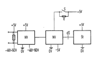
- the high-voltage part HV and the low-voltage part NV of the interface circuit and a central control unit St are shown in the figure, which can operate several subscriber circuits.
- the high-voltage part HV is operated here between a positive supply voltage of + 5V and a negative supply voltage of optionally 48V and -60V, depending on the length of the connected subscriber line TL.
- the high-voltage part HV is switched off in a manner not shown in order to reduce the power loss to reduce. So that an indication of the subscriber line status is nevertheless possible in this so-called power-down state, a separate indication circuit I is provided, which remains switched on continuously.
- the low-voltage part NV of the interface circuit is operated between the positive supply voltage + 5V and the negative supply voltage -5V.
- the positive supply voltage is supplied via a switch S, which is bridged by a resistor R. This switch is always open in the unoccupied state, so that the positive supply voltage + 5V is present across the resistor R mentioned. If the positive supply voltage is completely disconnected when the negative supply voltage -5V is applied unchanged, a potential change from positive potential to negative potential would take place at the digital interface dS to the central control unit ST, which could lead to the destruction of the components of the control unit.
- the resistor R bridging the switch S is dimensioned such that such a potential change cannot occur with the best possible reduction of the power loss.
Landscapes
- Engineering & Computer Science (AREA)
- Signal Processing (AREA)
- Interface Circuits In Exchanges (AREA)
- Devices For Supply Of Signal Current (AREA)
- Use Of Switch Circuits For Exchanges And Methods Of Control Of Multiplex Exchanges (AREA)
Abstract
Description
- Die Erfindung betrifft eine Teilnehmeranschlußschaltung einer digitalen Zeitmultiplex-Fernmeldevermittlungsstelle mit einer in einen Hochvoltteil und einen Niedervoltteil gegliederten Schnittstellenschaltung für den Anschluß einer analogen Teilnehmeranschlußleitung, bei der der Hochvoltteil in belegungsfreien Zeiten abgeschaltet ist und bei der der Niedervoltteil zwischen einer positiven und einer negativen Versorgungsspannung betrieben wird und über eine digitale Schnittstelle mit einer für mehrere Teilnehmeranschlußschaltungen zentralen Steuereinheit in Informationsaustausch steht.
- Die erwähnte Gliederung in Hochvoltteil und Niedervoltteil der Schnittstellenschaltung der vorausgesetzten Teilnehmeranschlußschaltung hat ihren Grund darin, daß derzeit eine Vollintegration aller Schnittstellenfunktionen noch nicht möglich ist. Wesentliche Funktionen des Hochvoltbausteins sind dabei die Speisefunktionen der Niedervoltteil realisiert dagegen in erster Linie die Regelfunktionen für den genannten Hochvoltbaustein sowie der Einspeisung der Ruf- und Gebührenimpulse.
- Die erwähnte Abschaltung von der Versorgungsspannung des Hochvoltteils in belegungsfreien Zeiten dient der Verlustleistungsreduzierung.
- Die Aufgabe der vorliegenden Erfindung besteht nun darin, die Verlustleistung weiter zu verringern, da hiervon die Lebensdauer eines Vermittlungssystems, bei dem eine große Vielzahl solcher Schnittstellenschaltungen vorhanden sind, entscheidend abhängt.
- Erfindungsgemäß wird diese Aufgabe dadurch gelöst, daß die eine der beiden Versorgungsspannungen des Niedervoltteils über einen durch einen Widerstand überbrückten Schalter zugeführt wird, der in der genannten belegungsfreien Zeit geöffnet ist, und daß der Widerstand einen derartigen Widerstandswert aufweist, daß durch Öffnen des Schalters bei unverändert anliegender anderer Versorgungsspannung die an der digitalen Schnittstelle vorhandene Spannung keinen Polaritätswechsel erfährt.
- Dadurch, daß bei der erfindungsgemäßen Lösung die eine Versorgungsspannung in belegungsfreien Zeiten nicht vollständig weggeschaltet wird, sondern über einen relativ hochohmigen Widerstand zugeführt wird, kann eine Verlustleistungsreduzierung erzielt werden, ohne daß ein Polaritätswechsel an der Schnittstelle zur zentralen Steuereinheit auftritt, der zu einer Zerstörung der elektronischen Bauelemente dieser Steuereinheit führen könnte. Im Hinblick auf den Aufwand ist diese Lösung günstiger als das Wegschalten beider Versorgungsspannungen, was bezüglich der Gefährdung der Bauelemente der zentralen Steuereinheit zum selben Ergebnis führen würde, da nur ein Schalter benötigt wird. Auf der anderen Seite würde unter dem Aspekt der Verlustleistungsreduzierung die Wegschaltung auch der anderen Versorgungsspannung nur eine geringfügige weitere Verbesserung mit sich bringen.
- Nachstehend wird die Erfindung anhand eines Ausführungsbeispiels unter Bezugnahme auf eine Zeichnung näher erläutert, die in Blockbildform Teile einer Teilnehmeranschlußschaltung einer digitalen Zeitmultiplex-Vermittlungsstelle zeigt.
- Von den Bestandteilen einer Teilnehmeranschlußschaltung sind in der Figur der Hochvoltteil HV und der Niedervoltteil NV der Schnittstellenschaltung sowie eine zentrale Steuereinheit St dargestellt, die mehrere Teilnehmerschaltungen bedienen kann. Der Hochvoltteil HV wird hier zwischen einer positiven Versorgungsspannung von +5V und einer negativen Versorgungsspannung von wahlweise 48V und -60V betrieben, je nach der Länge der angeschlossenen Teilnehmeranschlußleitung TL. In belegungsfreien Zeiten wird der Hochvoltteil HV in nicht dargestellter Weise abgeschaltet, um die Verlustleistung
zu verringern. Damit in diesen sogenannten Power-down-Zustand dennoch eine Indikation des Teilnehmerleitungszustandes möglich ist, ist eine gesonderte Indikationsschaltung I vorgesehen, die dauernd angeschaltet bleibt. - Der Niedervoltteil NV der Schnittstellenschaltung wird zwischen der positiven Versorgungsspannung +5V und der negativen Versorgungsspannung -5V betrieben. Die positive Versorgungsspannung wird über einen Schalter S zugeführt, der durch einen Widerstand R überbrückt ist. Dieser Schalter ist im belegungsfreien Zustand immer geöffnet, so daß die positive Versorgungsspannung +5V über den erwähnten Widerstand R anliegt. Bei einer völligen Abtrennung der positiven Versorgungsspannung bei unverändertem Anliegen der negativen Versorgungsspannung -5V würde an der digitalen Schnittstelle dS zur zentralen Steuereinheit ST ein Potentialwechsel von positivem Potential zu negativem Potential stattfinden, was zu einer Zerstörung der Bausteine oder Bauelemente der Steuereinheit führen könnte. Der den Schalter S überbrückende Widerstand R ist so bemessen, daß unter bestmöglicher Verringerung der Verlustleistung ein solcher Potentialwechsel aber nicht eintreten kann.
Claims (1)
dadurch gekennzeichnet, daß die eine der beiden Versorgungsspannungen (+5V) des Niedervoltteils (NV) über einen durch einen Widerstand (R) überbrückten Schalter (S) zugeführt wird, der in der genannten belegungsfreien Zeit geöffnet ist, und daß der Widerstand einen derartigen Widerstandswert aufweist, daß durch Öffnen des Schalters bei unverändert anliegender anderer Versorgungsspannung (-5V) des Niedervoltteils die an der digitalen Schnittstelle (S) vorhandene Spannung keinen Potentialwechsel erfährt.
Priority Applications (1)
| Application Number | Priority Date | Filing Date | Title |
|---|---|---|---|
| AT8989116474T ATE105127T1 (de) | 1988-09-30 | 1989-09-06 | Teilnehmeranschlussschaltung einer digitalen zeitmultiplex-fernmeldevermittlungsstelle. |
Applications Claiming Priority (2)
| Application Number | Priority Date | Filing Date | Title |
|---|---|---|---|
| DE3833313 | 1988-09-30 | ||
| DE3833313 | 1988-09-30 |
Publications (3)
| Publication Number | Publication Date |
|---|---|
| EP0361158A2 true EP0361158A2 (de) | 1990-04-04 |
| EP0361158A3 EP0361158A3 (de) | 1991-10-30 |
| EP0361158B1 EP0361158B1 (de) | 1994-04-27 |
Family
ID=6364114
Family Applications (1)
| Application Number | Title | Priority Date | Filing Date |
|---|---|---|---|
| EP89116474A Expired - Lifetime EP0361158B1 (de) | 1988-09-30 | 1989-09-06 | Teilnehmeranschlussschaltung einer digitalen Zeitmultiplex-Fernmeldevermittlungsstelle |
Country Status (4)
| Country | Link |
|---|---|
| EP (1) | EP0361158B1 (de) |
| AT (1) | ATE105127T1 (de) |
| DE (1) | DE58907562D1 (de) |
| ES (1) | ES2051947T3 (de) |
Family Cites Families (2)
| Publication number | Priority date | Publication date | Assignee | Title |
|---|---|---|---|---|
| FR2577737B1 (fr) * | 1985-02-15 | 1987-04-17 | Thomson Csf | Circuit d'interface de ligne d'abonne telephonique avec mode de veille a puissance reduite |
| DE3684744D1 (de) * | 1985-09-30 | 1992-05-14 | Siemens Ag | Schaltungsanordnung fuer eine elektronische schnittstellenschaltung. |
-
1989
- 1989-09-06 ES ES89116474T patent/ES2051947T3/es not_active Expired - Lifetime
- 1989-09-06 AT AT8989116474T patent/ATE105127T1/de not_active IP Right Cessation
- 1989-09-06 EP EP89116474A patent/EP0361158B1/de not_active Expired - Lifetime
- 1989-09-06 DE DE58907562T patent/DE58907562D1/de not_active Expired - Fee Related
Also Published As
| Publication number | Publication date |
|---|---|
| ES2051947T3 (es) | 1994-07-01 |
| ATE105127T1 (de) | 1994-05-15 |
| EP0361158A3 (de) | 1991-10-30 |
| EP0361158B1 (de) | 1994-04-27 |
| DE58907562D1 (de) | 1994-06-01 |
Similar Documents
| Publication | Publication Date | Title |
|---|---|---|
| DE2261400B2 (de) | Elektronische Schaltungsanordnung für das Halten von Verbindungswegen in einer Fernmelde-, insbesondere Fernsprechanlage | |
| EP0623267B1 (de) | Modulare teilnehmereinrichtung | |
| EP0361158B1 (de) | Teilnehmeranschlussschaltung einer digitalen Zeitmultiplex-Fernmeldevermittlungsstelle | |
| DE3628922C2 (de) | ||
| EP0217130B1 (de) | Schaltungsanordnung für eine elektronische Schnittstellenschaltung | |
| DE3803710A1 (de) | Schaltungsanordnung fuer fernsprechendgeraete | |
| DE4226834C2 (de) | ISDN-Abschlußeinrichtung | |
| DE2641967A1 (de) | Schaltungsanordnung zum betreiben eines tastenwahl-fernsprechapparates nach dem impulswahl-verfahren | |
| DE19636954B4 (de) | Teilnehmerschaltung | |
| DE3637053A1 (de) | Fernsprechschaltung | |
| EP0708575A2 (de) | Netzabschlusseinrichtung eines diensteintegrierenden digitalen Netzes | |
| EP0106247A1 (de) | Fernsprechanlage | |
| DE1219528B (de) | Stromversorgungsschaltung fuer eine Waehlscheibenbeleuchtung an Fernsprechteilnehmerapparaten | |
| EP0641113B1 (de) | Kennzeichenumsetzer mit Schutzschaltung | |
| EP0286793B1 (de) | Schaltungsanordnung für den Überspannungsschutz und die Rufstromeinspeisung an einer Anschlussleitung für Fernmelde-, insbesondere Fernsprechvermittlungsanlagen | |
| DE2942434A1 (de) | Schaltungsanordnung fuer fernmeldeanschluesse | |
| DE2536200C2 (de) | Schaltungsanordnung zur Überwachung einer Sprechader in Fernsprechapparaten | |
| EP0589085B1 (de) | Teilnehmeranschlusssatz für den Anschluss einer Fernsprech-Nebenstellenanlage an eine öffentliche Fernsprechvermittlungsstelle | |
| DE3416828A1 (de) | Digitales fernsprechteilnehmergeraet | |
| DE3641763C2 (de) | ||
| DE3528645C2 (de) | ||
| AT312060B (de) | Schaltungsanordnung zur Speisung einer Teilnehmerstelle und Aufnahme der Schleifenunterbrechungen von deiser bei Fernmelde-, insbesondere Fernsprechvermittlungsanlagen | |
| DE3134877C1 (de) | Identifiziereinheit für Teilnehmerendeinrichtungen | |
| DE3007549A1 (de) | Anordnung zur speisung einer teilnehmereinrichtung | |
| DE69017153T2 (de) | Adapteranordnung für eine integrierte Schaltung in einem Fernmeldegerät oder Endgerät ferngespeist durch eine analoge Leitung. |
Legal Events
| Date | Code | Title | Description |
|---|---|---|---|
| PUAI | Public reference made under article 153(3) epc to a published international application that has entered the european phase |
Free format text: ORIGINAL CODE: 0009012 |
|
| AK | Designated contracting states |
Kind code of ref document: A2 Designated state(s): AT BE CH DE ES FR GB GR IT LI NL SE |
|
| 17P | Request for examination filed |
Effective date: 19901205 |
|
| PUAL | Search report despatched |
Free format text: ORIGINAL CODE: 0009013 |
|
| AK | Designated contracting states |
Kind code of ref document: A3 Designated state(s): AT BE CH DE ES FR GB GR IT LI NL SE |
|
| 17Q | First examination report despatched |
Effective date: 19930929 |
|
| GRAA | (expected) grant |
Free format text: ORIGINAL CODE: 0009210 |
|
| AK | Designated contracting states |
Kind code of ref document: B1 Designated state(s): AT BE CH DE ES FR GB GR IT LI NL SE |
|
| REF | Corresponds to: |
Ref document number: 105127 Country of ref document: AT Date of ref document: 19940515 Kind code of ref document: T |
|
| REF | Corresponds to: |
Ref document number: 58907562 Country of ref document: DE Date of ref document: 19940601 |
|
| REG | Reference to a national code |
Ref country code: ES Ref legal event code: FG2A Ref document number: 2051947 Country of ref document: ES Kind code of ref document: T3 |
|
| ITF | It: translation for a ep patent filed | ||
| REG | Reference to a national code |
Ref country code: GR Ref legal event code: FG4A Free format text: 3011843 |
|
| GBT | Gb: translation of ep patent filed (gb section 77(6)(a)/1977) |
Effective date: 19940705 |
|
| ET | Fr: translation filed | ||
| EAL | Se: european patent in force in sweden |
Ref document number: 89116474.1 |
|
| PLBE | No opposition filed within time limit |
Free format text: ORIGINAL CODE: 0009261 |
|
| STAA | Information on the status of an ep patent application or granted ep patent |
Free format text: STATUS: NO OPPOSITION FILED WITHIN TIME LIMIT |
|
| 26N | No opposition filed | ||
| PGFP | Annual fee paid to national office [announced via postgrant information from national office to epo] |
Ref country code: DE Payment date: 19961118 Year of fee payment: 8 |
|
| PGFP | Annual fee paid to national office [announced via postgrant information from national office to epo] |
Ref country code: CH Payment date: 19961216 Year of fee payment: 8 |
|
| PGFP | Annual fee paid to national office [announced via postgrant information from national office to epo] |
Ref country code: GB Payment date: 19970826 Year of fee payment: 9 |
|
| PGFP | Annual fee paid to national office [announced via postgrant information from national office to epo] |
Ref country code: GR Payment date: 19970829 Year of fee payment: 9 |
|
| PGFP | Annual fee paid to national office [announced via postgrant information from national office to epo] |
Ref country code: AT Payment date: 19970904 Year of fee payment: 9 |
|
| PGFP | Annual fee paid to national office [announced via postgrant information from national office to epo] |
Ref country code: SE Payment date: 19970911 Year of fee payment: 9 |
|
| PGFP | Annual fee paid to national office [announced via postgrant information from national office to epo] |
Ref country code: ES Payment date: 19970912 Year of fee payment: 9 Ref country code: BE Payment date: 19970912 Year of fee payment: 9 |
|
| PGFP | Annual fee paid to national office [announced via postgrant information from national office to epo] |
Ref country code: NL Payment date: 19970918 Year of fee payment: 9 |
|
| PGFP | Annual fee paid to national office [announced via postgrant information from national office to epo] |
Ref country code: FR Payment date: 19970924 Year of fee payment: 9 |
|
| PG25 | Lapsed in a contracting state [announced via postgrant information from national office to epo] |
Ref country code: LI Free format text: LAPSE BECAUSE OF NON-PAYMENT OF DUE FEES Effective date: 19970930 Ref country code: CH Free format text: LAPSE BECAUSE OF NON-PAYMENT OF DUE FEES Effective date: 19970930 |
|
| REG | Reference to a national code |
Ref country code: CH Ref legal event code: PL |
|
| PG25 | Lapsed in a contracting state [announced via postgrant information from national office to epo] |
Ref country code: DE Free format text: LAPSE BECAUSE OF NON-PAYMENT OF DUE FEES Effective date: 19980603 |
|
| PG25 | Lapsed in a contracting state [announced via postgrant information from national office to epo] |
Ref country code: GB Free format text: LAPSE BECAUSE OF NON-PAYMENT OF DUE FEES Effective date: 19980906 Ref country code: AT Free format text: LAPSE BECAUSE OF NON-PAYMENT OF DUE FEES Effective date: 19980906 |
|
| PG25 | Lapsed in a contracting state [announced via postgrant information from national office to epo] |
Ref country code: SE Free format text: LAPSE BECAUSE OF NON-PAYMENT OF DUE FEES Effective date: 19980907 Ref country code: ES Free format text: LAPSE BECAUSE OF THE APPLICANT RENOUNCES Effective date: 19980907 |
|
| PG25 | Lapsed in a contracting state [announced via postgrant information from national office to epo] |
Ref country code: GR Free format text: LAPSE BECAUSE OF NON-PAYMENT OF DUE FEES Effective date: 19980930 Ref country code: BE Free format text: LAPSE BECAUSE OF NON-PAYMENT OF DUE FEES Effective date: 19980930 |
|
| BERE | Be: lapsed |
Owner name: SIEMENS A.G. Effective date: 19980930 |
|
| PG25 | Lapsed in a contracting state [announced via postgrant information from national office to epo] |
Ref country code: NL Free format text: LAPSE BECAUSE OF NON-PAYMENT OF DUE FEES Effective date: 19990401 |
|
| GBPC | Gb: european patent ceased through non-payment of renewal fee |
Effective date: 19980906 |
|
| EUG | Se: european patent has lapsed |
Ref document number: 89116474.1 |
|
| PG25 | Lapsed in a contracting state [announced via postgrant information from national office to epo] |
Ref country code: FR Free format text: LAPSE BECAUSE OF NON-PAYMENT OF DUE FEES Effective date: 19990531 |
|
| NLV4 | Nl: lapsed or anulled due to non-payment of the annual fee |
Effective date: 19990401 |
|
| REG | Reference to a national code |
Ref country code: FR Ref legal event code: ST |
|
| REG | Reference to a national code |
Ref country code: ES Ref legal event code: FD2A Effective date: 20001009 |
|
| PG25 | Lapsed in a contracting state [announced via postgrant information from national office to epo] |
Ref country code: IT Free format text: LAPSE BECAUSE OF NON-PAYMENT OF DUE FEES;WARNING: LAPSES OF ITALIAN PATENTS WITH EFFECTIVE DATE BEFORE 2007 MAY HAVE OCCURRED AT ANY TIME BEFORE 2007. THE CORRECT EFFECTIVE DATE MAY BE DIFFERENT FROM THE ONE RECORDED. Effective date: 20050906 |