EP0361208B1 - Wasserentnahmevorrichtung - Google Patents
Wasserentnahmevorrichtung Download PDFInfo
- Publication number
- EP0361208B1 EP0361208B1 EP89116904A EP89116904A EP0361208B1 EP 0361208 B1 EP0361208 B1 EP 0361208B1 EP 89116904 A EP89116904 A EP 89116904A EP 89116904 A EP89116904 A EP 89116904A EP 0361208 B1 EP0361208 B1 EP 0361208B1
- Authority
- EP
- European Patent Office
- Prior art keywords
- water
- water intake
- pipe
- reservoir
- strainer
- Prior art date
- Legal status (The legal status is an assumption and is not a legal conclusion. Google has not performed a legal analysis and makes no representation as to the accuracy of the status listed.)
- Expired - Lifetime
Links
- XLYOFNOQVPJJNP-UHFFFAOYSA-N water Substances O XLYOFNOQVPJJNP-UHFFFAOYSA-N 0.000 title claims description 68
- 239000003651 drinking water Substances 0.000 claims description 3
- 235000020188 drinking water Nutrition 0.000 claims description 3
- 238000006073 displacement reaction Methods 0.000 claims description 2
- 229910001220 stainless steel Inorganic materials 0.000 claims description 2
- 239000010935 stainless steel Substances 0.000 claims description 2
- 238000005070 sampling Methods 0.000 claims 1
- 238000007654 immersion Methods 0.000 description 3
- 238000005086 pumping Methods 0.000 description 3
- 238000007599 discharging Methods 0.000 description 2
- 230000008014 freezing Effects 0.000 description 2
- 238000007710 freezing Methods 0.000 description 2
- 238000011144 upstream manufacturing Methods 0.000 description 2
- 229910000906 Bronze Inorganic materials 0.000 description 1
- 241000195493 Cryptophyta Species 0.000 description 1
- 238000004458 analytical method Methods 0.000 description 1
- 239000010974 bronze Substances 0.000 description 1
- 238000004140 cleaning Methods 0.000 description 1
- 238000010276 construction Methods 0.000 description 1
- KUNSUQLRTQLHQQ-UHFFFAOYSA-N copper tin Chemical compound [Cu].[Sn] KUNSUQLRTQLHQQ-UHFFFAOYSA-N 0.000 description 1
- 230000008878 coupling Effects 0.000 description 1
- 238000010168 coupling process Methods 0.000 description 1
- 238000005859 coupling reaction Methods 0.000 description 1
- 230000001419 dependent effect Effects 0.000 description 1
- 239000012530 fluid Substances 0.000 description 1
- 239000012535 impurity Substances 0.000 description 1
- 238000009434 installation Methods 0.000 description 1
- 238000005461 lubrication Methods 0.000 description 1
- 238000012423 maintenance Methods 0.000 description 1
- 238000004519 manufacturing process Methods 0.000 description 1
- 238000005259 measurement Methods 0.000 description 1
- 238000000746 purification Methods 0.000 description 1
- 238000009423 ventilation Methods 0.000 description 1
- 239000002699 waste material Substances 0.000 description 1
- 238000004457 water analysis Methods 0.000 description 1
Images
Classifications
-
- E—FIXED CONSTRUCTIONS
- E02—HYDRAULIC ENGINEERING; FOUNDATIONS; SOIL SHIFTING
- E02B—HYDRAULIC ENGINEERING
- E02B9/00—Water-power plants; Layout, construction or equipment, methods of, or apparatus for, making same
- E02B9/02—Water-ways
- E02B9/04—Free-flow canals or flumes; Intakes
-
- E—FIXED CONSTRUCTIONS
- E03—WATER SUPPLY; SEWERAGE
- E03B—INSTALLATIONS OR METHODS FOR OBTAINING, COLLECTING, OR DISTRIBUTING WATER
- E03B3/00—Methods or installations for obtaining or collecting drinking water or tap water
- E03B3/04—Methods or installations for obtaining or collecting drinking water or tap water from surface water
-
- Y—GENERAL TAGGING OF NEW TECHNOLOGICAL DEVELOPMENTS; GENERAL TAGGING OF CROSS-SECTIONAL TECHNOLOGIES SPANNING OVER SEVERAL SECTIONS OF THE IPC; TECHNICAL SUBJECTS COVERED BY FORMER USPC CROSS-REFERENCE ART COLLECTIONS [XRACs] AND DIGESTS
- Y02—TECHNOLOGIES OR APPLICATIONS FOR MITIGATION OR ADAPTATION AGAINST CLIMATE CHANGE
- Y02E—REDUCTION OF GREENHOUSE GAS [GHG] EMISSIONS, RELATED TO ENERGY GENERATION, TRANSMISSION OR DISTRIBUTION
- Y02E10/00—Energy generation through renewable energy sources
- Y02E10/20—Hydro energy
-
- Y—GENERAL TAGGING OF NEW TECHNOLOGICAL DEVELOPMENTS; GENERAL TAGGING OF CROSS-SECTIONAL TECHNOLOGIES SPANNING OVER SEVERAL SECTIONS OF THE IPC; TECHNICAL SUBJECTS COVERED BY FORMER USPC CROSS-REFERENCE ART COLLECTIONS [XRACs] AND DIGESTS
- Y02—TECHNOLOGIES OR APPLICATIONS FOR MITIGATION OR ADAPTATION AGAINST CLIMATE CHANGE
- Y02P—CLIMATE CHANGE MITIGATION TECHNOLOGIES IN THE PRODUCTION OR PROCESSING OF GOODS
- Y02P70/00—Climate change mitigation technologies in the production process for final industrial or consumer products
- Y02P70/50—Manufacturing or production processes characterised by the final manufactured product
Definitions
- the present invention relates to a device for taking water from a natural or artificial water reservoir, in particular from the reservoir of a dam for the production of drinking water, comprising a water intake tube provided, at one end, a suction strainer and, at the other end, a transverse branch so that said water intake tube has substantially the shape of a "T", bearings which are integral with '' a fixed supporting structure installed in the tank, said bearings supporting the transverse branches of the tube so that the latter can pivot around a horizontal axis O defined by said bearings, an articulated connection integral with one of the two ends of said branch transverse to connect the water intake tube to a water evacuation pipe, drive means for rotating the tube and modifying the level of water intake by the strainer.
- the suction strainers for the intake of drinking water into the reservoir of a dam are generally fixed on the upstream side of the wall of the dam at the end of a pipe crossing the bottom of this dam and connected, on the side downstream, to a pumping station.
- Such a location has, however, several drawbacks.
- the strainer is difficult to access for the maintenance and cleaning it requires from time to time.
- the water intake in the immediate vicinity of the dam is not an ideal position, because of the impurities and waste that accumulate there.
- the fixed location of the suction strainer does not allow fluctuations in the water quality to be taken into account. It has been found that the quality of water can vary according to the seasons and according to the level of depth. For example, the algae which generally spread out in sheets go up or down according to the seasons.
- a device which is provided with a variable level water intake is known from document JP-A-603,314. More specifically a device for taking water from a reservoir of a dam which has a first water intake secured to a body floating on the water body of the reservoir (that is to say an intake water with fixed immersion depth) and a second water intake whose immersion depth can be adjusted.
- the device of document JP-A-603 314 is provided with a tube which is connected with one of its ends using a joint articulated on a submerged pipe, so as to be able to pivot around a horizontal axis.
- the free end of this tube, which constitutes the second water intake with variable immersion depth is connected by a cable to a winch installed on said floating body. By operating the winch, you can change the level at which the water intake is made.
- the object of the present invention is to provide a new water intake device which makes it possible to adjust the level of water intake as a function of the quality of the water and which does not have the abovementioned drawbacks.
- a water intake device as defined in the preamble, which is characterized in that said water intake device composed of said tube, said bearings, said articulated connection and said drive means, is fully immersed in said water tank and in that said drive means are actuated with water.
- the pivoting of the water intake tube is generated by a jack mounted on the frame and actuated using pressurized water, withdrawn by the tube and under the control of a magnetic valve in a control station installed dry next to the hard tank.
- This embodiment has the advantage that it allows the installation of the dry control station next to the water tank and which, therefore, is less dangerous and easier to access and that it is not dependent on climatic hazards, such as the freezing of the water body.
- the tube is preferably extended, beyond its pivot axis, by a balancing weight, allowing the tube to be in equilibrium around its pivot axis, so that it is enough for the jack to overcome dynamic forces and friction.
- the position of the tube can be determined using pressure sensors. This measurement is preferably done in a differential manner thanks to a first pressure sensor mounted on the tube near the strainer and a second pressure sensor mounted on the frame.
- a device for taking samples of the collected water allows a permanent analysis in the control station in order to actuate the jack to ensure an optimal position of the suction strainer.
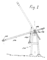
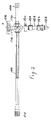
- Figures 1 and 2 show a water intake tube 110 provided, at its free end, with a suction strainer 112 and mounted, by its opposite end, pivotally, on a frame so as to be able to be moved between the upper and lower extreme positions shown in broken lines in Fig. 1.
- the frame is fully submerged while a control station not shown is installed dry next to the water tank.
- the frame is constituted by a tripod 114 produced by a welded tubular construction in stainless steel, comprising ventilation holes to avoid an upward force.
- the console 114 essentially consists of several feet anchored securely in concrete foundations at a distance of the order of a hundred meters upstream from the dike of a not shown dam.
- the tube 110 is in the form of a "T" whose transverse branch 116 is housed horizontally in two bearings 118, 120 fixed to the top of the console 114.
- the tube 110 can therefore pivot around the horizontal axis O of its transverse branch 116 to occupy any desired position between the extreme angular positions shown in FIG. 3.
- the transverse branch 116 of the tube 110 is connected to a fixed pipe 122 for discharging the water collected through the strainer 112 and the tube 110.
- This pipe 122 directs the water to a treatment and purification station, possibly through a pumping station.
- the pivoting section 116 is connected to the fixed pipe by means of two rotary couplings 124, 126 with spherical ball joints provided on either side of a floating section 128 so as to allow relative axial and radial displacements between the section swivel 116 and the fixed pipe 122.
- Both the bearings 118 and 120, as well as the fittings 124 and 126 include plastic or bronze shells which allow rotation or pivoting without the need for lubrication.
- the pivoting of the tube 110 is generated by means of a jack 130 mounted on the console 114 and the hydraulic fluid of which is advantageously water withdrawn by the tube 110 through the pipe 122. If the device is associated with a pumping station for discharging the water to a treatment station, the water has, moreover, the pressure required to actuate the jack 130.
- the control of the jack 130 is carried out through pipes not shown, connected by the bottom from the water tank to the control station located next to the water surface.
- the water flow rate actuating the actuator 130 is adjusted using a magnetic valve.
- the tube 110 is preferably extended beyond the cross section 116 by a section 132 provided with a weight 134 for balancing the rest of the tube 110 so that the latter is in equilibrium around its axis of pivoting. In this way, the jack 130 will only have to overcome the dynamic forces and those caused by friction at the bearings and fittings.
- the actuator 130 is controlled by an operator as a function of the water analysis results so as to place the strainer 112 at the level corresponding to the optimal quality of the water.
- the evacuation pipe 122 is associated with a sample taking system for permanently analyzing the water withdrawn. If the quality of the water drops, the position of the tube 110 can be modified to find a level where the water is of better quality. Alternatively, it is possible to perform time in time, a scan of the tube 110 between the two extreme positions in order to determine the level or the quality of the water is the best.
- the device is preferably associated with a device for detecting the position of the arm 110 and the strainer 112 in order to permanently inform the operator at the control station of the exact position of the tube 110 or else to activate the cylinder 130 so as to place the tube 110 in a determined position.
- This measuring device is advantageously based on the fact that the pressure in the water gradually increases with depth.
Landscapes
- Engineering & Computer Science (AREA)
- General Engineering & Computer Science (AREA)
- Mechanical Engineering (AREA)
- Civil Engineering (AREA)
- Structural Engineering (AREA)
- Environmental & Geological Engineering (AREA)
- Health & Medical Sciences (AREA)
- Life Sciences & Earth Sciences (AREA)
- Hydrology & Water Resources (AREA)
- Public Health (AREA)
- Water Supply & Treatment (AREA)
- Sampling And Sample Adjustment (AREA)
Claims (9)
- Vorrichtung zur Wasserentnahme in einem natürlichen oder künstlichen Wasserreservoir, insbesondere in dem Reservoir eines Staudamms, mit dem Ziel der Gewinnung von Trinkwasser, aus einem Wasserentnahmerohr (110), das an einem Ende mit einem Saugkorb (112), und an dem anderen Ende mit einem Querschenkel (116) versehen ist, so daß das Wasserentnahmerohr im wesentlichen die Form eines "T" hat, Lagern (118, 120), die mit einer in dem Reservoir installierten, stationären Tragstruktur fest verbunden sind, wobei diese Lager den Querschenkel (116) des Rohrs (110) so tragen, daß das Rohr um eine horizontale Achse O, die durch die Lager (118, 120) festgelegt wird, schwenkbar ist, einem Gelenk-Anschlußstück (124, 126), das mit einem der zwei Enden des Querschenkels (116) verbunden ist, um das Wasserentnahmerohr (110) mit einer Wasserabführleitung (122) zu verbinden, und Antriebsmitteln, um das Rohr zu schwenken und das Niveau der Wasserentnahme durch den Saugkorb zu ändern, dadurch gekennzeichnet, daß diese Vorrichtung zur Wasserentnahme, die aus dem Rohr (110), den Lagern (118, 120), dem Gelenk-Anschlußstück (124, 126), und den Antriebsmitteln (130) besteht, vollständig in das Wasserreservoir eingetaucht ist, und daß die Antriebsmittel mit Wasser betätigt werden.
- Vorrichtung gemäß Anspruch 1, dadurch gekennzeichnet, daß die Antriebsmittel einen Hubzylinder (130) umfassen, der mit Druckwasser betätigt wird und zwischen der Tragstruktur (114) und dem Wasserentnahmerohr (110) angebracht ist.
- Vorrichtung gemäß Anspruch 1 oder 2, dadurch gekennzeichnet, daß die Antriebsmittel von einer Steuerstation aus ferngesteuert werden.
- Vorrichtung gemäß Anspruch 3, gekennzeichnet durch eine fernsteuerbare Einrichtung zur Probenentnahme in verschiedenen Tiefen.
- Vorrichtung gemäß irgendeinem der Ansprüche 1 bis 4, dadurch gekennzeichnet, daß die in dem Reservoir installierte Tragstruktur ein Gerüst aus rostfreiem Stahl ist, das auf dem Boden des Reservoirs verankert ist und vollständig in das Wasser eingetaucht ist.
- Vorrichtung gemäß irgendeinem der Ansprüche 1 bis 5, dadurch gekennzeichnet, daß die Position des Wasserentnahme-Saugkorbs (112) mit Hilfe von Druckfühlern bestimmt wird.
- Vorrichtung gemäß Anspruch 6, gekennzeichnet durch einen ersten Druckfühler, der auf dem Rohr (110) in der Nähe des Saugkorbs (112) angebracht ist, und einen zweiten Druckfühler, der auf der stationären Tragstruktur (114) angebracht ist.
- Vorrichtung gemäß irgendeinem der Ansprüche 1 bis 7, dadurch gekennzeichnet, daß das Wasserentnahmerohr (110) durch ein Gegengewicht bis über seine Schwenkachse O hinaus verlängert ist.
- Vorrichtung gemäß irgendeinem der Ansprüche 1 bis 8, dadurch gekennzeichnet, daß dieses Gelenk-Ansatzstück zwei Kugelgelenk-Drehanschlüsse (124, 126) umfaßt, die auf beiden Seiten eines schwimmenden Abschnitts (128) vorgesehen sind, so daß axiale und radiale relative Verschiebungen zwischen dem Querschenkel (116) und der Abführrohrleitung (122) möglich sind.
Priority Applications (1)
| Application Number | Priority Date | Filing Date | Title |
|---|---|---|---|
| AT89116904T ATE89358T1 (de) | 1988-09-28 | 1989-09-13 | Wasserentnahmevorrichtung. |
Applications Claiming Priority (4)
| Application Number | Priority Date | Filing Date | Title |
|---|---|---|---|
| LU87349 | 1988-09-28 | ||
| LU87349A LU87349A1 (fr) | 1988-09-28 | 1988-09-28 | Dispositif de prise d'eau |
| LU87468 | 1989-03-06 | ||
| LU87468A LU87468A1 (fr) | 1989-03-06 | 1989-03-06 | Dispositif de prise d'eau |
Publications (3)
| Publication Number | Publication Date |
|---|---|
| EP0361208A2 EP0361208A2 (de) | 1990-04-04 |
| EP0361208A3 EP0361208A3 (en) | 1990-10-24 |
| EP0361208B1 true EP0361208B1 (de) | 1993-05-12 |
Family
ID=26640332
Family Applications (1)
| Application Number | Title | Priority Date | Filing Date |
|---|---|---|---|
| EP89116904A Expired - Lifetime EP0361208B1 (de) | 1988-09-28 | 1989-09-13 | Wasserentnahmevorrichtung |
Country Status (3)
| Country | Link |
|---|---|
| EP (1) | EP0361208B1 (de) |
| DE (1) | DE68906494T2 (de) |
| ES (1) | ES2042919T3 (de) |
Cited By (1)
| Publication number | Priority date | Publication date | Assignee | Title |
|---|---|---|---|---|
| DE102008049693A1 (de) | 2008-09-19 | 2010-04-01 | Technische Universität Dresden | Höhenverstellbare Wasserentnahmevorrichtung für Talsperren und Seen |
Families Citing this family (4)
| Publication number | Priority date | Publication date | Assignee | Title |
|---|---|---|---|---|
| DE4241888C1 (de) * | 1992-12-11 | 1994-05-11 | Georg Klas | Schlammsaugewagen |
| AU2001276037A1 (en) * | 2000-07-24 | 2002-02-05 | Asc Group Inc. | Selective reservoir withdrawal system |
| DE102018112789A1 (de) * | 2018-05-29 | 2019-12-05 | H2U aqua . plan . Ing - GmbH | Tiefenverstellbares Entnahmesystem zur Entnahme von Wasser aus Wasserreservoiren |
| CN109579948B (zh) * | 2019-01-16 | 2023-03-24 | 南昌工程学院 | 一种多功能河道水位监测装置 |
Family Cites Families (2)
| Publication number | Priority date | Publication date | Assignee | Title |
|---|---|---|---|---|
| FR2098967A5 (de) * | 1970-07-31 | 1972-03-10 | Amenagement Urbain Rural | |
| CA1012841A (en) * | 1975-03-07 | 1977-06-28 | Lloyd Kosmachuk | Pumping apparatus |
-
1989
- 1989-09-13 EP EP89116904A patent/EP0361208B1/de not_active Expired - Lifetime
- 1989-09-13 ES ES89116904T patent/ES2042919T3/es not_active Expired - Lifetime
- 1989-09-13 DE DE8989116904T patent/DE68906494T2/de not_active Expired - Fee Related
Cited By (1)
| Publication number | Priority date | Publication date | Assignee | Title |
|---|---|---|---|---|
| DE102008049693A1 (de) | 2008-09-19 | 2010-04-01 | Technische Universität Dresden | Höhenverstellbare Wasserentnahmevorrichtung für Talsperren und Seen |
Also Published As
| Publication number | Publication date |
|---|---|
| DE68906494T2 (de) | 1993-09-09 |
| ES2042919T3 (es) | 1993-12-16 |
| EP0361208A3 (en) | 1990-10-24 |
| EP0361208A2 (de) | 1990-04-04 |
| DE68906494D1 (de) | 1993-06-17 |
Similar Documents
| Publication | Publication Date | Title |
|---|---|---|
| CA2714625C (fr) | Support flottant equipe de touret comprenant des paliers de roulement hors d'eau | |
| EP2286056B1 (de) | Boden-oberfläche-verbindung aus einem starren steigrohr mit flexiblem kanal mit positiver flotation | |
| EP2255065B1 (de) | Verfahren zur installation eines unterwasser-steigrohrs | |
| FR2543611A1 (fr) | Joint telescopique pour colonne montante servant a des recherches petrolieres sous l'eau | |
| FR2544688A1 (fr) | Systeme modulaire de production, de stockage et de chargement d'hydrocarbures au large des cotes | |
| JP3923710B2 (ja) | 水サンプリング装置 | |
| EP2571753B1 (de) | Vorrichtung für eine verbindung zwischen meeresgrund und oberfläche mit einer flexiblen rohrführungsstruktur | |
| FR2519783A1 (fr) | Vanne separant un bassin amont et un bassin aval et permettant le maintien automatique a une valeur constante et reglable du niveau de l'un des bassins | |
| WO2004070165A1 (fr) | Dispositif de collecte de produit et/ou de tranquillisation d'une colonne en milieu sous-marin et son utilisation | |
| FR2908800A1 (fr) | Unite mobile de nettoyage d'un reseau d'egout | |
| EP0361208A2 (de) | Wasserentnahmevorrichtung | |
| FR2545437A1 (fr) | Dispositif immerge d'amarrage a un point, en particulier pour ancrer des petroliers dans les eaux arctiques | |
| EP1925756A1 (de) | Untersuchungsbrunnen für Kanalisationsnetz, der mindestens einen Anschlussstutzen mit einem schwenkbaren Verbindungselement umfasst | |
| LU87468A1 (fr) | Dispositif de prise d'eau | |
| MC1342A1 (fr) | Bouee d'amarrage pour bateaux-citerne | |
| FR2797465A1 (fr) | Support flottant comportant une cavitee centrale comprenant une pluralite de compartiments | |
| FR2702047A1 (fr) | Dispositif de prélèvements d'échantillons ou de mesures de grandeurs physiques dans un milieu sous-marin. | |
| LU87349A1 (fr) | Dispositif de prise d'eau | |
| FR2868446A1 (fr) | Ensemble charge de recueillir les fuites de petroles d'une epave | |
| EP4379184A1 (de) | Kopfabdeckungsvorrichtung und bohrlochpumpstation | |
| FR2522771A1 (fr) | Dispositif de reglage, commande par flotteur, pour modifier le diametre d'un tuyau | |
| FR2684701A1 (fr) | Dispositif pour l'elimination des flottants au droit des siphons d'emissaires. | |
| FR2549800A1 (fr) | Systeme d'amarrage d'un corps flottant de grandes dimensions | |
| BE535989A (de) | ||
| EP2689093B1 (de) | Verfahren zur unterstützten installation eines unterwassersteigrohrs |
Legal Events
| Date | Code | Title | Description |
|---|---|---|---|
| PUAI | Public reference made under article 153(3) epc to a published international application that has entered the european phase |
Free format text: ORIGINAL CODE: 0009012 |
|
| AK | Designated contracting states |
Kind code of ref document: A2 Designated state(s): AT BE CH DE ES FR IT LI |
|
| PUAL | Search report despatched |
Free format text: ORIGINAL CODE: 0009013 |
|
| AK | Designated contracting states |
Kind code of ref document: A3 Designated state(s): AT BE CH DE ES FR IT LI |
|
| 17P | Request for examination filed |
Effective date: 19910304 |
|
| 17Q | First examination report despatched |
Effective date: 19911024 |
|
| GRAA | (expected) grant |
Free format text: ORIGINAL CODE: 0009210 |
|
| RAP3 | Party data changed (applicant data changed or rights of an application transferred) |
Owner name: S.E.B.E.S. (SYNDICAT DES EAUX DU BARRAGE D'ESCH-S Owner name: PAUL WURTH S.A. |
|
| AK | Designated contracting states |
Kind code of ref document: B1 Designated state(s): AT BE CH DE ES FR IT LI |
|
| REF | Corresponds to: |
Ref document number: 89358 Country of ref document: AT Date of ref document: 19930515 Kind code of ref document: T |
|
| REF | Corresponds to: |
Ref document number: 68906494 Country of ref document: DE Date of ref document: 19930617 |
|
| ITF | It: translation for a ep patent filed | ||
| REG | Reference to a national code |
Ref country code: ES Ref legal event code: FG2A Ref document number: 2042919 Country of ref document: ES Kind code of ref document: T3 |
|
| PGFP | Annual fee paid to national office [announced via postgrant information from national office to epo] |
Ref country code: DE Payment date: 20020809 Year of fee payment: 14 |
|
| PGFP | Annual fee paid to national office [announced via postgrant information from national office to epo] |
Ref country code: CH Payment date: 20020819 Year of fee payment: 14 |
|
| PGFP | Annual fee paid to national office [announced via postgrant information from national office to epo] |
Ref country code: FR Payment date: 20030813 Year of fee payment: 15 |
|
| PGFP | Annual fee paid to national office [announced via postgrant information from national office to epo] |
Ref country code: AT Payment date: 20030819 Year of fee payment: 15 |
|
| PGFP | Annual fee paid to national office [announced via postgrant information from national office to epo] |
Ref country code: BE Payment date: 20030912 Year of fee payment: 15 |
|
| PG25 | Lapsed in a contracting state [announced via postgrant information from national office to epo] |
Ref country code: LI Free format text: LAPSE BECAUSE OF NON-PAYMENT OF DUE FEES Effective date: 20030930 Ref country code: CH Free format text: LAPSE BECAUSE OF NON-PAYMENT OF DUE FEES Effective date: 20030930 |
|
| PG25 | Lapsed in a contracting state [announced via postgrant information from national office to epo] |
Ref country code: DE Free format text: LAPSE BECAUSE OF NON-PAYMENT OF DUE FEES Effective date: 20040401 |
|
| REG | Reference to a national code |
Ref country code: CH Ref legal event code: PL |
|
| PG25 | Lapsed in a contracting state [announced via postgrant information from national office to epo] |
Ref country code: AT Free format text: LAPSE BECAUSE OF NON-PAYMENT OF DUE FEES Effective date: 20040913 |
|
| PG25 | Lapsed in a contracting state [announced via postgrant information from national office to epo] |
Ref country code: BE Free format text: LAPSE BECAUSE OF NON-PAYMENT OF DUE FEES Effective date: 20040930 |
|
| BERE | Be: lapsed |
Owner name: SYNDICAT DES EAUX DU BARRAGE D'ESCH-SUR-SURE *SEBE Effective date: 20040930 Owner name: S.A. PAUL *WURTH Effective date: 20040930 |
|
| PG25 | Lapsed in a contracting state [announced via postgrant information from national office to epo] |
Ref country code: FR Free format text: LAPSE BECAUSE OF NON-PAYMENT OF DUE FEES Effective date: 20050531 |
|
| REG | Reference to a national code |
Ref country code: FR Ref legal event code: ST |
|
| PGFP | Annual fee paid to national office [announced via postgrant information from national office to epo] |
Ref country code: ES Payment date: 20070816 Year of fee payment: 19 |
|
| BERE | Be: lapsed |
Owner name: S.A. PAUL *WURTH Effective date: 20040930 Owner name: SYNDICAT DES EAUX DU BARRAGE D'ESCH-SUR-SURE *SEBE Effective date: 20040930 |
|
| PGFP | Annual fee paid to national office [announced via postgrant information from national office to epo] |
Ref country code: IT Payment date: 20070926 Year of fee payment: 19 |
|
| PG25 | Lapsed in a contracting state [announced via postgrant information from national office to epo] |
Ref country code: IT Free format text: LAPSE BECAUSE OF NON-PAYMENT OF DUE FEES Effective date: 20080913 |
|
| REG | Reference to a national code |
Ref country code: ES Ref legal event code: FD2A Effective date: 20080915 |
|
| PG25 | Lapsed in a contracting state [announced via postgrant information from national office to epo] |
Ref country code: ES Free format text: LAPSE BECAUSE OF NON-PAYMENT OF DUE FEES Effective date: 20080915 |
|
| PLBE | No opposition filed within time limit |
Free format text: ORIGINAL CODE: 0009261 |
|
| STAA | Information on the status of an ep patent application or granted ep patent |
Free format text: STATUS: NO OPPOSITION FILED WITHIN TIME LIMIT |