EP0361227A2 - Traverse de chemin de fer en béton précontraint - Google Patents
Traverse de chemin de fer en béton précontraint Download PDFInfo
- Publication number
- EP0361227A2 EP0361227A2 EP89117094A EP89117094A EP0361227A2 EP 0361227 A2 EP0361227 A2 EP 0361227A2 EP 89117094 A EP89117094 A EP 89117094A EP 89117094 A EP89117094 A EP 89117094A EP 0361227 A2 EP0361227 A2 EP 0361227A2
- Authority
- EP
- European Patent Office
- Prior art keywords
- sleeper
- prestressed concrete
- tensioning elements
- threshold
- elements
- Prior art date
- Legal status (The legal status is an assumption and is not a legal conclusion. Google has not performed a legal analysis and makes no representation as to the accuracy of the status listed.)
- Granted
Links
- 241001669679 Eleotris Species 0.000 title claims abstract description 73
- 239000011513 prestressed concrete Substances 0.000 title claims abstract description 34
- 229910000831 Steel Inorganic materials 0.000 claims abstract description 5
- 239000010959 steel Substances 0.000 claims abstract description 5
- 238000004519 manufacturing process Methods 0.000 claims description 10
- 238000009415 formwork Methods 0.000 claims description 7
- 230000002787 reinforcement Effects 0.000 claims description 6
- 238000005452 bending Methods 0.000 abstract description 8
- 238000009827 uniform distribution Methods 0.000 abstract description 4
- 238000004873 anchoring Methods 0.000 description 2
- 238000009826 distribution Methods 0.000 description 2
- 238000000034 method Methods 0.000 description 2
- 239000000853 adhesive Substances 0.000 description 1
- 230000001070 adhesive effect Effects 0.000 description 1
- 230000015572 biosynthetic process Effects 0.000 description 1
- 239000004567 concrete Substances 0.000 description 1
- 238000010924 continuous production Methods 0.000 description 1
- 230000007423 decrease Effects 0.000 description 1
- 230000002349 favourable effect Effects 0.000 description 1
- 239000002184 metal Substances 0.000 description 1
- 239000011150 reinforced concrete Substances 0.000 description 1
Images


Classifications
-
- E—FIXED CONSTRUCTIONS
- E01—CONSTRUCTION OF ROADS, RAILWAYS, OR BRIDGES
- E01B—PERMANENT WAY; PERMANENT-WAY TOOLS; MACHINES FOR MAKING RAILWAYS OF ALL KINDS
- E01B3/00—Transverse or longitudinal sleepers; Other means resting directly on the ballastway for supporting rails
- E01B3/28—Transverse or longitudinal sleepers; Other means resting directly on the ballastway for supporting rails made from concrete or from natural or artificial stone
- E01B3/32—Transverse or longitudinal sleepers; Other means resting directly on the ballastway for supporting rails made from concrete or from natural or artificial stone with armouring or reinforcement
- E01B3/34—Transverse or longitudinal sleepers; Other means resting directly on the ballastway for supporting rails made from concrete or from natural or artificial stone with armouring or reinforcement with pre-tensioned armouring or reinforcement
Definitions
- the invention relates to a railway sleeper made of prestressed concrete with a monolithic sleeper body consisting of two support bodies supporting the fastening parts for the rails and a middle part connecting them and with a reinforcement made of tensioning elements, and a method for their production.
- the threshold body of prestressed concrete sleepers usually has a prismatic shape. This results in higher bending moments compared to a sleeper body with a slim middle section; however, these are accepted in favor of a simple linear guidance of the tensioning elements. A pronounced reduction in cross-section in the middle part of the sleeper body is not possible in any case with prestressed concrete sleepers, since the position of the individual tensioning elements is determined from the outset by the necessary uniform distribution of their end anchorages over the cross-sectional areas of the sleeper ends.
- the invention has for its object to provide a way for a railway sleeper made of prestressed concrete in order to be able to reduce the cross section of the sleeper body in the middle part of the sleeper compared to the support bodies, while maintaining the uniform distribution of the end anchorages of the tensioning elements, so as to achieve a more favorable distribution of the bending moments to come.
- this object is achieved in a railway sleeper made of prestressed concrete in that the central part has a smaller cross-section than the support body and the tensioning elements, starting from a junction in a vertical and / or horizontal plane in the middle of the sleeper, radiating essentially straight to the sleeper ends and the ends of the tensioning elements being distributed substantially uniformly over the cross-sectional areas of the sleeper ends.
- the tensioning elements can run in a straight line between their end regions and intersect in the middle of the threshold.
- two clamping elements running at the same angle, but inclined in opposite directions to the threshold axis, in mutually parallel planes can form a pair of clamping elements.
- at least two pairs of clamping elements can be arranged side by side or one above the other, or one pair of clamping elements can be arranged between a further pair of clamping elements.
- Two clamping elements can be connected to each other at one end by a curved part like a loop.
- An embodiment is particularly useful for the production of sleepers in a long fitted bed in each case two tensioning elements arranged on the sleeper ends at the same distance from a cross-sectional axis are brought together in the middle of the sleeper and held by means of a connecting part.
- the use of a sleeper body with a high, narrow central web and wide sleeper ends is also possible for prestressed concrete sleepers, with only slight alternating bending moments occurring in the middle section, yes even a unidirectionally positive course of the bending moments over the entire threshold length can be made possible.
- a uniform distribution of the end anchorages over the respective cross-sectional area of the sleeper ends can be achieved.
- a staggered arrangement of the end anchorages allows the tensioning elements to be positioned very eccentrically in the cross-section of the sleeper.
- a sleeper body when the tensioning elements are brought together in a horizontal plane, a sleeper body can also be constructed, the middle part of which has a flat rectangular cross section and is therefore largely elastic.
- the amount of prestressing steel customary in known sleepers decreases from approx. 5 kg per sleeper according to the invention by up to 40% to approx. 3 kg per sleeper.
- the invention also relates to a method for producing prestressed concrete sleepers in a long way Clamping bed, along which stretching elements that can be clamped against fixed abutments extend, in the area of which successive stations are provided for the continuous production of the prestressed concrete sleepers in formwork forms, in which the clamping elements are initially laid out in parallel and stretched, then at each production station in the respective formwork form merged in pairs in the middle of the threshold and held by means of connecting parts.
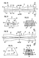
- the sleeper body 1 consists of two comparatively wide lateral support bodies 2, 2 ', which carry the - rail fastening, not shown for the sake of clarity, and one Middle part 3 with a comparatively narrow, high cross-section.
- the sleeper body 1 is reinforced with four straight clamping elements 4, which are anchored at the sleeper ends 5, 5 'by means of end anchors 6.
- the tensioning elements 1 consist of steel rods, wires or strands and are guided so that they lie one above the other in a vertical plane V-V in the middle of the threshold (FIG. 4) and spread out radially towards the threshold ends 5, 5 '.
- Your end anchorages 6 are distributed as evenly as possible over the surface of the preferably trapezoidal cross section at the threshold ends 5, 5 '(Fig. 3). This arrangement allows the formation of a very slim middle part while maintaining sufficient concrete coverage.
- the geometry of the radiating clamping elements 4, which can be seen in FIG. 1, does not permit an arrangement symmetrical to the vertical center line of the cross section V-V. If the usual conditions for prestressed concrete sleepers are met, that the prestressing must not result in any horizontal bending moments and no torsional moments, because these would lead to undesirable deformations and twists of the sleeper, so there are only a few options for distributing the end anchorages 6 at the sleeper ends 5, the most important of which are shown in FIGS. 3 and 5.
- FIG. 2 and 3 show the combination of two clamping elements 4a, 4b and 4c, 4d to form a pair of clamping elements.
- the tensioning elements 4a, 4b and 4c, 4d of each pair of tensioning elements each have an inclination of the same size but in opposite directions with respect to the longitudinal axis of the threshold LL (FIG. 1) and run in horizontal planes parallel to one another (FIGS. 2 and 3).
- the inclinations to one another and the distances between the clamping elements 4a, 4b and 4c, 4d, which form a pair, are so chosen that no torsional moments occur.
- the end anchors 6 are arranged on both threshold ends 5, 5 'in the same way.
- FIG. 5 it is also indicated in FIG. 5 how the clamping elements 4c and 4d forming a pair can also be arranged between the clamping elements 4a and 4b forming the other pair in order to avoid the generation of torsional moments.
- each with four individual straight tensioning elements 4 can provide further other options for the distribution of the end anchors 6. It is also possible to insert individual clamping elements lying in the vertical plane V-V and running parallel to the longitudinal axis L-L.
- the sleeper body 21 between the support bodies 22, 22 ' has a central part 23 with a low wide cross section in the middle of the sleeper; such thresholds are known as "elastic middle part" thresholds.
- the guidance of the tensioning elements 24 results from the fact that the arrangement described in connection with the embodiment according to FIGS. 6 to 9 is rotated by 90 degrees against the longitudinal axis of the threshold. 10 shows in longitudinal section the position of two pairs of tensioning elements 24a, 24b and 24c, 24d, which, starting from the middle of the sleeper (section XII-XII), radiate upwards and downwards. As shown above all in FIG. 12, all tensioning elements 24 lie in a horizontal plane H-H in the middle of the threshold.
- FIG. 11 shows the view of the threshold end 25.
- the basic arrangement of the pairs of tensioning elements 24a, 24b and 24c, 24d corresponds to that in FIG. 8 after rotation by 90 degrees about the longitudinal axis of the threshold.
- the tensioning elements 24c, 24d in turn lie between the tensioning elements 24a, 24b of the other pair.
- clamping elements 24 with curved deflection points 27 are shown, the use of individual straight clamping elements 24 with end anchorages 6 at both ends is also possible here.
- FIG. 13 The schematic plan view of a sleeper body 31 according to FIG. 13 with wide support bodies 32, 32 'and a flat middle part 33 again shows straight clamping elements 34 which are brought together in pairs in the middle of the sleeper (section XV-XV) towards the longitudinal axis LL and are held by a connecting part 38 .
- a connecting part 38 here designed as a clamp, is necessary in each position of the tensioning elements 34.
- the design of the connecting part 38 as a clamp has the advantage that it can be placed on the side of the tensioning elements 34 in the course of the tensioning elements 34, so that they do not have to be threaded through a ring.
- the prestressing elements along the prestressing path are usually first laid out in parallel with one another and tensioned against fixed abutments.
- the clamping elements 34 are guided in a conventional manner in slot-like recesses in the end faces of the formwork.
- the tensioning elements 34 are then paired in the middle of the threshold in the area of the first formwork Merged using a suitable device and held by means of the connecting parts 38 made of metal or plastic.
- the tensioning force that increases due to the merging of the tensioning elements can be automatically reduced to the intended setpoint by a controller on the tensioning press of the movable tensioning track abutment.
Landscapes
- Engineering & Computer Science (AREA)
- Architecture (AREA)
- Civil Engineering (AREA)
- Structural Engineering (AREA)
- Railway Tracks (AREA)
- Bridges Or Land Bridges (AREA)
- Train Traffic Observation, Control, And Security (AREA)
- Reinforcement Elements For Buildings (AREA)
Priority Applications (1)
| Application Number | Priority Date | Filing Date | Title |
|---|---|---|---|
| AT89117094T ATE81691T1 (de) | 1988-09-24 | 1989-09-15 | Eisenbahnschwelle aus spannbeton. |
Applications Claiming Priority (2)
| Application Number | Priority Date | Filing Date | Title |
|---|---|---|---|
| DE3832504 | 1988-09-24 | ||
| DE3832504A DE3832504A1 (de) | 1988-09-24 | 1988-09-24 | Eisenbahnschwelle aus spannbeton |
Publications (3)
| Publication Number | Publication Date |
|---|---|
| EP0361227A2 true EP0361227A2 (fr) | 1990-04-04 |
| EP0361227A3 EP0361227A3 (en) | 1990-06-20 |
| EP0361227B1 EP0361227B1 (fr) | 1992-10-21 |
Family
ID=6363648
Family Applications (1)
| Application Number | Title | Priority Date | Filing Date |
|---|---|---|---|
| EP89117094A Expired - Lifetime EP0361227B1 (fr) | 1988-09-24 | 1989-09-15 | Traverse de chemin de fer en béton précontraint |
Country Status (5)
| Country | Link |
|---|---|
| EP (1) | EP0361227B1 (fr) |
| AT (1) | ATE81691T1 (fr) |
| DE (1) | DE3832504A1 (fr) |
| ES (1) | ES2036011T3 (fr) |
| MX (1) | MX172187B (fr) |
Cited By (3)
| Publication number | Priority date | Publication date | Assignee | Title |
|---|---|---|---|---|
| US5135164A (en) * | 1990-09-07 | 1992-08-04 | Dyckerhoff & Widmann Aktiengesellschaft | Prestressed concrete railroad tie |
| CN103334350A (zh) * | 2013-07-16 | 2013-10-02 | 天津银龙预应力材料股份有限公司 | 一种预应力混凝土轨枕、轨道板用搓丝定尺螺旋肋钢丝 |
| CN111231105A (zh) * | 2020-03-24 | 2020-06-05 | 北京智创赋能技术开发中心(有限合伙) | 一种预应力轨枕钢筋自动穿丝机构 |
Families Citing this family (4)
| Publication number | Priority date | Publication date | Assignee | Title |
|---|---|---|---|---|
| DE4203895C2 (de) * | 1992-02-11 | 1996-08-29 | Dyckerhoff & Widmann Ag | Einrichtung zum Herstellen von Fertigbauteilen aus Spannbeton mit sofortigem Verbund, insbesondere von Spannbetonschwellen |
| DE4344253A1 (de) * | 1993-12-23 | 1995-06-29 | Butzbacher Weichenbau Gmbh | Schwelle |
| DE9411341U1 (de) * | 1994-07-13 | 1994-09-15 | Pfleiderer Verkehrstechnik Gmbh & Co Kg, 92318 Neumarkt | Monoblock-Schwelle |
| MX2014008112A (es) | 2014-07-01 | 2016-01-01 | Bienracon S De Rl De Cv | Durmiente monolítico ultrarresistente de concreto presforzado de forma integral con geometría óptima para vías férreas balastradas. |
Family Cites Families (7)
| Publication number | Priority date | Publication date | Assignee | Title |
|---|---|---|---|---|
| FR960117A (fr) * | 1950-04-13 | |||
| CH37979A (de) * | 1907-04-15 | 1907-10-15 | Gottlieb Strahm | Eisenbahnquerschwelle aus eisenarmiertem Beton |
| FR680547A (fr) * | 1928-10-02 | 1930-05-01 | Procédé de fabrication de pièces en béton armé | |
| CH213850A (de) * | 1940-01-18 | 1941-03-31 | Rueping Max | Eisenbeton-Querschwelle. |
| DE803728C (de) * | 1950-01-18 | 1951-04-09 | Ludwig Jubitz Dipl Ing | Verfahren zum Vorspannen von Stahlbeton-Umschnuerungen |
| DE937827C (de) * | 1954-03-28 | 1956-01-19 | Dyckerhoff & Widmann Ag | Eisenbahnschwelle aus Stahlbeton |
| DE1247188B (de) * | 1962-03-16 | 1967-08-10 | Emch & Berger Ingenieurbuero G | Verfahren zum Herstellen von Spannbetonschwellen |
-
1988
- 1988-09-24 DE DE3832504A patent/DE3832504A1/de active Granted
-
1989
- 1989-09-15 ES ES198989117094T patent/ES2036011T3/es not_active Expired - Lifetime
- 1989-09-15 EP EP89117094A patent/EP0361227B1/fr not_active Expired - Lifetime
- 1989-09-15 AT AT89117094T patent/ATE81691T1/de not_active IP Right Cessation
- 1989-09-21 MX MX017633A patent/MX172187B/es unknown
Cited By (4)
| Publication number | Priority date | Publication date | Assignee | Title |
|---|---|---|---|---|
| US5135164A (en) * | 1990-09-07 | 1992-08-04 | Dyckerhoff & Widmann Aktiengesellschaft | Prestressed concrete railroad tie |
| CN103334350A (zh) * | 2013-07-16 | 2013-10-02 | 天津银龙预应力材料股份有限公司 | 一种预应力混凝土轨枕、轨道板用搓丝定尺螺旋肋钢丝 |
| CN103334350B (zh) * | 2013-07-16 | 2015-08-12 | 中国铁道科学研究院铁道建筑研究所 | 一种预应力混凝土轨枕、轨道板用搓丝定尺螺旋肋钢丝 |
| CN111231105A (zh) * | 2020-03-24 | 2020-06-05 | 北京智创赋能技术开发中心(有限合伙) | 一种预应力轨枕钢筋自动穿丝机构 |
Also Published As
| Publication number | Publication date |
|---|---|
| ATE81691T1 (de) | 1992-11-15 |
| EP0361227A3 (en) | 1990-06-20 |
| MX172187B (es) | 1993-12-07 |
| EP0361227B1 (fr) | 1992-10-21 |
| DE3832504C2 (fr) | 1991-12-12 |
| ES2036011T3 (es) | 1993-05-01 |
| DE3832504A1 (de) | 1990-04-05 |
Similar Documents
| Publication | Publication Date | Title |
|---|---|---|
| AT390111B (de) | Schalung zur errichtung von baukoerpern aus gussfaehigen materialien, wie beispielsweise beton | |
| DE102007008704A1 (de) | Betonschwelle und Verfahren zu ihrer Herstellung | |
| DE69410077T2 (de) | Vorgefertigter stahlbetonverbundträger | |
| DE2164417B2 (de) | Fachwerkträger und Verfahren zum Herstellen desselben | |
| DE2712808A1 (de) | Verankerungsvorrichtung fuer befestigungsorgane in einem betonteil | |
| EP0361227B1 (fr) | Traverse de chemin de fer en béton précontraint | |
| DE2534076A1 (de) | Vorrichtung und verfahren zum ausrichten von eckverbindern | |
| CH672816A5 (fr) | ||
| DE3874539T2 (de) | Gittertraeger. | |
| CH625586A5 (fr) | ||
| DE2119731A1 (de) | Träger mit durchgebrochenem Steg, sowie Verfahren zur Herstellung desselben | |
| DE29602463U1 (de) | Zweiblock-Schwelle | |
| DE3716833A1 (de) | Verfahren zur herstellung von vorgespannten stahltraegern, sowie die hierdurch erhaltenen traeger | |
| EP1486628B1 (fr) | Poutre en treillis | |
| DE1941329A1 (de) | Vorrichtung zur Herstellung eines vorgebogenen Traegers | |
| DE852140C (de) | Verfahren zur Herstellung von gespannten Traegern oder gespannten Decken und danach hergestellte Traeger oder Decken | |
| DE3337006T (de) | Verfahren zum Tragen eines Metallblechdachs und Dachkonstruktion zur Durchführung des Verfahrens | |
| DE60007824T2 (de) | Gitterträger | |
| DE7525732U (de) | Verbundtraeger | |
| DE2329943A1 (de) | Gittertraeger | |
| DE1156960B (de) | Raeumlicher Fachwerktraeger, insbesondere fuer Betonrippendecken | |
| DE19856434C1 (de) | Betonbrücke mit externer Vorspannung | |
| DE2844151C2 (de) | Zeltkonstruktion | |
| EP1932978A1 (fr) | Elément d'armature pour l'absorption de forces dans des plaques de béton dans la zone d'éléments d'appui | |
| DE2911535A1 (de) | Beton-profilbalken zur herstellung von spalten-, insbesondere rinderspaltenboeden, mit als steife bewehrung eingelagertem, geschweisstem raeumlichem drahtgittertraeger von v-foermigem querschnitt sowie verfahren zum verbuegeln und abbiegen sowie zum aufspreizen der drahtgittertraeger |
Legal Events
| Date | Code | Title | Description |
|---|---|---|---|
| PUAI | Public reference made under article 153(3) epc to a published international application that has entered the european phase |
Free format text: ORIGINAL CODE: 0009012 |
|
| AK | Designated contracting states |
Kind code of ref document: A2 Designated state(s): AT CH ES IT LI |
|
| PUAL | Search report despatched |
Free format text: ORIGINAL CODE: 0009013 |
|
| AK | Designated contracting states |
Kind code of ref document: A3 Designated state(s): AT CH ES IT LI |
|
| 17P | Request for examination filed |
Effective date: 19900606 |
|
| 17Q | First examination report despatched |
Effective date: 19910703 |
|
| GRAA | (expected) grant |
Free format text: ORIGINAL CODE: 0009210 |
|
| AK | Designated contracting states |
Kind code of ref document: B1 Designated state(s): AT CH ES IT LI |
|
| REF | Corresponds to: |
Ref document number: 81691 Country of ref document: AT Date of ref document: 19921115 Kind code of ref document: T |
|
| ITF | It: translation for a ep patent filed | ||
| REG | Reference to a national code |
Ref country code: ES Ref legal event code: FG2A Ref document number: 2036011 Country of ref document: ES Kind code of ref document: T3 |
|
| PLBE | No opposition filed within time limit |
Free format text: ORIGINAL CODE: 0009261 |
|
| STAA | Information on the status of an ep patent application or granted ep patent |
Free format text: STATUS: NO OPPOSITION FILED WITHIN TIME LIMIT |
|
| 26N | No opposition filed | ||
| REG | Reference to a national code |
Ref country code: ES Ref legal event code: FD2A Effective date: 20001102 |
|
| REG | Reference to a national code |
Ref country code: CH Ref legal event code: PUE Owner name: DYWIDAG-SYSTEMS INTERNATIONAL GMBH Free format text: DYCKERHOFF & WIDMANN AKTIENGESELLSCHAFT#ERDINGER LANDSTRASSE 1#D-81902 MUENCHEN (DE) -TRANSFER TO- DYWIDAG-SYSTEMS INTERNATIONAL GMBH#DYWIDAGSTRASSE 1#85609 ASCHHEIM (DE) Ref country code: CH Ref legal event code: NV Representative=s name: PATENTANWAELTE FELDMANN & PARTNER AG |
|
| REG | Reference to a national code |
Ref country code: ES Ref legal event code: PC2A |
|
| REG | Reference to a national code |
Ref country code: ES Ref legal event code: FD2A Effective date: 19971011 |
|
| REG | Reference to a national code |
Ref country code: ES Ref legal event code: FD2A Effective date: 19960916 |
|
| REG | Reference to a national code |
Ref country code: ES Ref legal event code: NE1A |
|
| REG | Reference to a national code |
Ref country code: ES Ref legal event code: NF1A |
|
| REG | Reference to a national code |
Ref country code: ES Ref legal event code: FD2A Effective date: 19960916 |
|
| REG | Reference to a national code |
Ref country code: ES Ref legal event code: FD2A Effective date: 19960916 |
|
| PGFP | Annual fee paid to national office [announced via postgrant information from national office to epo] |
Ref country code: CH Payment date: 20080923 Year of fee payment: 20 Ref country code: ES Payment date: 20080922 Year of fee payment: 20 |
|
| PGFP | Annual fee paid to national office [announced via postgrant information from national office to epo] |
Ref country code: AT Payment date: 20080924 Year of fee payment: 20 Ref country code: IT Payment date: 20080926 Year of fee payment: 20 |
|
| REG | Reference to a national code |
Ref country code: CH Ref legal event code: PL |
|
| REG | Reference to a national code |
Ref country code: ES Ref legal event code: FD2A Effective date: 20090916 |
|
| PG25 | Lapsed in a contracting state [announced via postgrant information from national office to epo] |
Ref country code: ES Free format text: LAPSE BECAUSE OF EXPIRATION OF PROTECTION Effective date: 20090916 |