EP0361277B1 - Filtre à compost pour le renouvellement continu du lit filtrant pour la purification et la désodorisation d'émissions gazeuses pendant le compostage de résidus solides urbains et similaires - Google Patents
Filtre à compost pour le renouvellement continu du lit filtrant pour la purification et la désodorisation d'émissions gazeuses pendant le compostage de résidus solides urbains et similaires Download PDFInfo
- Publication number
- EP0361277B1 EP0361277B1 EP89117284A EP89117284A EP0361277B1 EP 0361277 B1 EP0361277 B1 EP 0361277B1 EP 89117284 A EP89117284 A EP 89117284A EP 89117284 A EP89117284 A EP 89117284A EP 0361277 B1 EP0361277 B1 EP 0361277B1
- Authority
- EP
- European Patent Office
- Prior art keywords
- filter
- compost
- gas
- purified
- fact
- Prior art date
- Legal status (The legal status is an assumption and is not a legal conclusion. Google has not performed a legal analysis and makes no representation as to the accuracy of the status listed.)
- Expired - Lifetime
Links
- 239000002361 compost Substances 0.000 title claims abstract description 45
- 239000002699 waste material Substances 0.000 title claims description 6
- 238000009264 composting Methods 0.000 title claims description 4
- 239000007787 solid Substances 0.000 title claims description 4
- 238000004332 deodorization Methods 0.000 title 1
- 238000000746 purification Methods 0.000 title 1
- 239000002184 metal Substances 0.000 claims abstract description 6
- 238000007599 discharging Methods 0.000 claims abstract description 4
- 239000007789 gas Substances 0.000 claims description 33
- 238000009826 distribution Methods 0.000 claims description 6
- 239000004809 Teflon Substances 0.000 claims description 2
- 229920006362 Teflon® Polymers 0.000 claims description 2
- 230000001877 deodorizing effect Effects 0.000 claims description 2
- 230000008030 elimination Effects 0.000 claims description 2
- 238000003379 elimination reaction Methods 0.000 claims description 2
- 239000002245 particle Substances 0.000 claims description 2
- 239000003831 antifriction material Substances 0.000 claims 1
- 238000001914 filtration Methods 0.000 description 9
- 239000011796 hollow space material Substances 0.000 description 8
- 238000000034 method Methods 0.000 description 7
- 239000000463 material Substances 0.000 description 4
- 239000000126 substance Substances 0.000 description 4
- 239000002028 Biomass Substances 0.000 description 3
- 238000010521 absorption reaction Methods 0.000 description 3
- 230000036983 biotransformation Effects 0.000 description 3
- 238000004140 cleaning Methods 0.000 description 3
- 238000003860 storage Methods 0.000 description 3
- 230000015572 biosynthetic process Effects 0.000 description 2
- 239000013590 bulk material Substances 0.000 description 2
- 230000008878 coupling Effects 0.000 description 2
- 238000010168 coupling process Methods 0.000 description 2
- 238000005859 coupling reaction Methods 0.000 description 2
- 239000000428 dust Substances 0.000 description 2
- 239000003337 fertilizer Substances 0.000 description 2
- 238000009434 installation Methods 0.000 description 2
- 239000005416 organic matter Substances 0.000 description 2
- 230000000284 resting effect Effects 0.000 description 2
- 229920006395 saturated elastomer Polymers 0.000 description 2
- 229930182555 Penicillin Natural products 0.000 description 1
- JGSARLDLIJGVTE-MBNYWOFBSA-N Penicillin G Chemical compound N([C@H]1[C@H]2SC([C@@H](N2C1=O)C(O)=O)(C)C)C(=O)CC1=CC=CC=C1 JGSARLDLIJGVTE-MBNYWOFBSA-N 0.000 description 1
- 244000052616 bacterial pathogen Species 0.000 description 1
- 229920002678 cellulose Polymers 0.000 description 1
- 239000001913 cellulose Substances 0.000 description 1
- 238000006243 chemical reaction Methods 0.000 description 1
- 239000003153 chemical reaction reagent Substances 0.000 description 1
- 239000010840 domestic wastewater Substances 0.000 description 1
- 229920001971 elastomer Polymers 0.000 description 1
- 239000003925 fat Substances 0.000 description 1
- 230000005484 gravity Effects 0.000 description 1
- 229920002521 macromolecule Polymers 0.000 description 1
- 239000003595 mist Substances 0.000 description 1
- 230000003647 oxidation Effects 0.000 description 1
- 238000007254 oxidation reaction Methods 0.000 description 1
- 230000001717 pathogenic effect Effects 0.000 description 1
- 238000005453 pelletization Methods 0.000 description 1
- 229940049954 penicillin Drugs 0.000 description 1
- 239000004033 plastic Substances 0.000 description 1
- 230000000750 progressive effect Effects 0.000 description 1
- 102000004169 proteins and genes Human genes 0.000 description 1
- 108090000623 proteins and genes Proteins 0.000 description 1
- 238000007670 refining Methods 0.000 description 1
- 230000000717 retained effect Effects 0.000 description 1
- 238000011012 sanitization Methods 0.000 description 1
- 239000010801 sewage sludge Substances 0.000 description 1
- 235000000346 sugar Nutrition 0.000 description 1
- 150000008163 sugars Chemical class 0.000 description 1
- 239000002912 waste gas Substances 0.000 description 1
Images

Classifications
-
- B—PERFORMING OPERATIONS; TRANSPORTING
- B01—PHYSICAL OR CHEMICAL PROCESSES OR APPARATUS IN GENERAL
- B01D—SEPARATION
- B01D53/00—Separation of gases or vapours; Recovering vapours of volatile solvents from gases; Chemical or biological purification of waste gases, e.g. engine exhaust gases, smoke, fumes, flue gases, aerosols
- B01D53/34—Chemical or biological purification of waste gases
- B01D53/74—General processes for purification of waste gases; Apparatus or devices specially adapted therefor
- B01D53/84—Biological processes
- B01D53/85—Biological processes with gas-solid contact
-
- Y—GENERAL TAGGING OF NEW TECHNOLOGICAL DEVELOPMENTS; GENERAL TAGGING OF CROSS-SECTIONAL TECHNOLOGIES SPANNING OVER SEVERAL SECTIONS OF THE IPC; TECHNICAL SUBJECTS COVERED BY FORMER USPC CROSS-REFERENCE ART COLLECTIONS [XRACs] AND DIGESTS
- Y02—TECHNOLOGIES OR APPLICATIONS FOR MITIGATION OR ADAPTATION AGAINST CLIMATE CHANGE
- Y02A—TECHNOLOGIES FOR ADAPTATION TO CLIMATE CHANGE
- Y02A50/00—TECHNOLOGIES FOR ADAPTATION TO CLIMATE CHANGE in human health protection, e.g. against extreme weather
- Y02A50/20—Air quality improvement or preservation, e.g. vehicle emission control or emission reduction by using catalytic converters
Definitions
- the gas usually trapped at the base of the stokpile, is cooled down and condenses into a mist.
- the compost which is soft and porous, can successfully act as a filter bed and offers the advantage of being locally available.
- the compost when used as a filter bed, loses its filtering capacity. This means that the filter has to be continuously provided with fresh compost while the depleted and drenched compost has to be continuously removed.
- This invention has the aim to provide a compost filter, apt to meet the requirements for successfully and continuously to filter off gas emissions from biotransformation processes and progressively to replace the depleted compost by fresh compost in order to ensure efficient filtration.
- This invention has the aim radically to solve the problem through the implementation of a compost filter with a continuously renewed filter bed by progressive elimination from below, of the drenched compost which has completely lost its absorption capacity, fresh compost being continously added at the filter top and in which the gas to be purified flows diagonally in countercurrent, from the bottom upwards, through the increasingly fresher and better filtering compost layer, until the purified gas is discharged at the top of the filter by an exhaust fan and released into the atmosphere.
- EP-A-0132503 a process for the cleaning of highly polluted gas produced by industries and urban incinerators. This process foresees the flow of the gas across a highly active bio-mass containing Actynomiceties and Penicillin. Reagents are added to the gas to clean, so that the purified gas contains less than 150 mg/m3 of organic substances.
- the WO-A-8803434 foresees a reactor for the cleaning of gas, which passes diagonally by means of shutters through a downward moving layer of granular absorption.
- EP-A-0154684 it is foreseen a cell filter containing the filtering substance and in DE-A-2605606 it is foreseen a filter with filtering masses traversed vertically by the gas to clean.
- the DE-A-3030562 states a particular solution with a multiplicity of superposed chambers provided with lateral openings; these chambers contain the filtering material and they are traversed horizontally by the gas.
- Document JP-A-5653726 represents the most relevant state of the art. It shows a compost filter suitable for purifying and deodorizing gaseous emissions developed during composting of solid urban waste and/or biological sludges comprising the features of the preamble of claim 1. Starting from this disclosure problems occur with the uniformity of the flow of waste gases and the uniformity of the continuously lowering of the compost mass. These problems are solved by the features of the characterizing part of claim 1.
- This hollow space H is filled with fresh compost charged at the top of the filter by a levelling screw feeder 3, which in turn receives the fresh compost from a bin with rotary valve 5 to prevent unwanted air from entering the hollow space H or gas from leaving the filter when pressurized.
- the feed capacity of the screw feeder 3 shall be greater than the capacity of the rotary valve 5 and the latter shall have a greater capacity than the maximum capacity of the conveyers to be installed ahead of this valve.
- the screw feeder 3 has the important function to distribute the compost evenly in the whole space H.
- the delivery rate of the fresh compost shall of course be greater than the quantity of compost removed by the apron conveyer at the bottom of the filter.
- a certain portion of the compost entering the filter by means of the rotary valve 5 and levelling screw feeder 3 will be in excess and has to be conveyed by the srew feeder 3 to the outlet duct 6 to be discharged by the rotary valve 7 for further processing (e.g. refining, mixing with other fertilizers, pelletizing, storage and maturing etc )
- the charged compost which has lost most of its absorption and filtering capacity, is discharged at the bottom of the hollow space H of the filter by means of a appropriate continuous discharging device the capacity of which shall be stepless adjustable.
- this discharging system is consisting of an apron conveyer with linenized rubber belt 4.
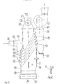
- the section AA in fig. 1 clearly shows that this chamber 13, outwards delimited by the front wall 14 and by the sidewalls 15 and 16 (fig.2), is delimited at the rear by the filter wall a on which it is resting.
- This wall a delimiting one side of the filter cavity H, as explained above, has an opening 17 connecting the hollow space H to the distribution chamber 13.
- This opening 17 is delimited at its upper and lower end respectively by the edpes t and t′ of the port in the filter wall a and laterally by the edges of the sidewalls 15 and 16 laterally delimiting the front distribution chamber 13. It can be observed in fig. 1 that the sidewall a is not flat since its vertical section extending from the coupling flange of the cover 2 to the upper edge t of the opening 17 is followed by an outwards slanting section, t, t′ featuring the opening 17. This is followed by a third section of the vertical wall a located between the edge t′ and the flange coupling the conveyor bin 18 to the apron conveyer 4.
- the opening 17 is closed by a "shutter” type device consisting of blades 9 having parallel horizontal longitudinal axes and strongly downwards slanting, but also parallel, transverses axes, as illustrated in fig.1.
- the edge of the blades facing the hollow space H of the filter is located on the plane identified by the upper edge t and lower edge t′ of the opening in the wall a .
- the blades 9 are further stiffened by plates 10 thus conferring a considerable strength to the "shutter” structure,
- This "shutter” has the function to permit the guided flow of the gas and vapour to be filtered from the front distribution chamber 13 to the hollow space H in the filter, while preventing at the same time the compost in H from suddenly entering the chamber 13.
- the filter can function without the above described "shutter", simply by preparing an opening (17) so that the compost can freely be gravity discharged from H into the chamber 13.
- the gases entering the hollow filter space H are drawn upwards and leave the filter through a second "shutter” consisting of blades 9′ fitted in a recess 17′ implemented, according to the same criteria, in the upper portion of the filter wall b opposite the gas inlet wall a .
- This second shutter 17′ connects the hollow space H to the suction chamber 19 which, in turn, is connected to a suction fan 11 by means of the nozzle 20. Dust and plastic shreds may collect in the suction chamber 19, to be discharged at intervals through the trap 21.
- the wall opposite each "shutter" shall be perfectly vertical to ensure efficient operation of the filter and to prevent the formation of "hangings" which would hinder the descend of the compost.
- the "shutter” is braking the compost in its downward movement.
- the wall opposite the “shutter” shall therefore be perfectly smooth to prevent the formation of "scaffolds” so that the compost, which is retained on one side, will slide down along the opposite side without forming any hangings.
- the latter are covered with teflon sheets glued onto the vertical or subvertical metal walls 1, as shown in fig.2.
Landscapes
- Engineering & Computer Science (AREA)
- Chemical & Material Sciences (AREA)
- Biomedical Technology (AREA)
- Environmental & Geological Engineering (AREA)
- Health & Medical Sciences (AREA)
- Life Sciences & Earth Sciences (AREA)
- Molecular Biology (AREA)
- Analytical Chemistry (AREA)
- General Chemical & Material Sciences (AREA)
- Oil, Petroleum & Natural Gas (AREA)
- Chemical Kinetics & Catalysis (AREA)
- Fertilizers (AREA)
- Treating Waste Gases (AREA)
Claims (7)
- Filtre à compost pour purifier et désodoriser les émissions gazeuses formées pendant le compostage des résidus solides urbains et/ou des boues biologiques, comprenant :- un caisson métallique (1) constitué par des paires de parois opposées (a,b-c,d) en formant ainsi une chambre (H) ;- un système d'alimentation supérieur étanche et un dispositif de nivellement (3) pour le compost frais introduit dans la chambre (H) ;- un mécanisme étanche (4) pour évacuer le compost usé en bas du caisson métallique (1) ;- un dispositif (8 à 16) introduisant le gaz à purifier ;- un ventilateur d'aspiration (11, 19) pour l'élimination des gaz purifiés par la sortie (17′) du filtre ;- un évidement (17) dans la partie inférieure de la paroi (a) du filtre jouant le rôle d'entrée de gaz ;- un obturateur constitué par des lames (9) parallèles, horizontales, inclinées vers le bas, pour assurer la distribution du gaz et pour retenir le compost, situé dans l'évidement (17) ;
caractérisé par :- un évidement (17′) dans la partie supérieure de la paroi opposée (b) jouant le rôle de sortie pour le gaz purifié ;- un obturateur constitué par des lames (9′) parallèles, horizontales inclinées vers le bas, permettant aux gaz de quitter l'espace de filtrage (H) et permettant de retenir le compost, situé dans l'évidement de sortie (17′) ;- les parois (a, b) du filtre se caractérisant par des évidements (17, 17′) inclinées vers l'extérieur, tandis que les parois (b, a) opposées à ces ouvertures (17, 17′) sont verticales. - Filtre selon la revendication 1, caractérisé par le fait que le système d'alimentation en compost comprend un système d'alimentation à vis (3), un dispositif doseur (5) alimentant la vis sans fin et un dispositif réglable (7) pour dégager l'excès de compost.
- Filtre selon la revendication 2, caractérisé par le fait que la capacité du système d'alimentation à vis (3) est supérieure à la capacité de décharge du convoyeur inférieur (4) installé en bas du filtre afin que le filtre soit toujours rempli de compost à niveau.
- Filtre selon la revendication 1, caractérisé par le fait que le dispositif introduisant le gaz à purifier est constitué d'une chambre de distribution (13) située à l'extérieur de l'ouverture d'entrée (17).
- Filtre selon la revendication 1, caractérisé par le fait que le dispositif pour dégager le gaz purifié comprend une chambre (19) située à l'extérieur de l'ouverture de sortie (17′) reliée au ventilateur d'aspiration (11) pour dégager le gaz purifié dans l'atmosphère et équipée d'une trappe (21) pour dégager les éventuelles particules entraînées par le gaz.
- Filtre selon la revendication 1, caractérisé par le fait que les parois (1) du filtre sont revêtues intérieurement d'un matériau anti-friction (1′) tel que du téflon pour empêcher le compost de coller sur les parois métalliques.
- Filtre selon la revendication 1, caractérisé par le fait que le bord inférieur (t′) de l'ouverture d'entrée du gaz (17) est situé dans le plan de la bande convoyeuse inférieure (4).
Priority Applications (1)
| Application Number | Priority Date | Filing Date | Title |
|---|---|---|---|
| AT89117284T ATE82870T1 (de) | 1988-09-28 | 1989-09-19 | Kompostfilter zur kontinuierlichen erneuerung des filterbetts zur reinigung und deodorierung von gasfoermigen emissionen waehrend der kompostierung von festem stadtmuell und aehnlichem muell. |
Applications Claiming Priority (2)
| Application Number | Priority Date | Filing Date | Title |
|---|---|---|---|
| IT6520888 | 1988-09-28 | ||
| IT8865208A IT1225748B (it) | 1988-09-28 | 1988-09-28 | Filtro a compost a rinnovo continuo del letto filtrante per la depurazione e deodorizzazione delle emissioni gassose svolte nel corso dei processi di compostaggio dei rifiuti solidi urbani (rsu) e rifiuti assimilabili agli urbani |
Publications (3)
| Publication Number | Publication Date |
|---|---|
| EP0361277A2 EP0361277A2 (fr) | 1990-04-04 |
| EP0361277A3 EP0361277A3 (en) | 1990-10-10 |
| EP0361277B1 true EP0361277B1 (fr) | 1992-12-02 |
Family
ID=11297713
Family Applications (1)
| Application Number | Title | Priority Date | Filing Date |
|---|---|---|---|
| EP89117284A Expired - Lifetime EP0361277B1 (fr) | 1988-09-28 | 1989-09-19 | Filtre à compost pour le renouvellement continu du lit filtrant pour la purification et la désodorisation d'émissions gazeuses pendant le compostage de résidus solides urbains et similaires |
Country Status (4)
| Country | Link |
|---|---|
| EP (1) | EP0361277B1 (fr) |
| AT (1) | ATE82870T1 (fr) |
| DE (2) | DE68903719T2 (fr) |
| IT (1) | IT1225748B (fr) |
Families Citing this family (5)
| Publication number | Priority date | Publication date | Assignee | Title |
|---|---|---|---|---|
| DE4017384C2 (de) * | 1990-05-30 | 1994-11-17 | Linde Ag | Plattenbiofilter |
| NO175896C (no) * | 1991-09-20 | 1994-12-28 | Svein Tegle | Fremgangsmåte til nöytralisering og gjenvinning av gasser som frigjöres ved våtkompostering av husdyrgjödsel og kloakkslam og lignende masser, samt anlegg til utförelse av fremgangsmåten. |
| CN1331819C (zh) * | 2006-07-06 | 2007-08-15 | 上海交通大学 | 利用污泥粉煤灰混合造粒净化气体并副产复合肥料的方法 |
| EP2796533A1 (fr) * | 2013-04-25 | 2014-10-29 | Danieli Corus BV | Système et procédé de conditionnement de matières particulaires |
| CN113209768A (zh) * | 2021-04-22 | 2021-08-06 | 广东顶通环境科技有限公司 | 一种用于槽式堆肥发酵废气净化装置 |
Family Cites Families (7)
| Publication number | Priority date | Publication date | Assignee | Title |
|---|---|---|---|---|
| US2962122A (en) * | 1955-09-14 | 1960-11-29 | Linderoths Patenter Ab | Dust separator |
| DE2605606A1 (de) * | 1976-02-12 | 1977-08-18 | Kneer Franz X | Einrichtung zum abscheiden gasfoermiger organischer verunreinigungen aus abgasen |
| DE3030562A1 (de) * | 1979-08-16 | 1981-03-26 | Sumitomo Heavy Industries | Mehrstufen-fliessbett-adsorptionsvorrichtung |
| DE3322688A1 (de) * | 1983-06-23 | 1985-01-10 | Gebrüder Weiss KG, 6340 Dillenburg | Verfahren zum abscheiden gasfoermiger, fluechtiger und/oder fluessiger verunreinigungen aus abgasen |
| DE3414044A1 (de) * | 1983-12-16 | 1985-06-27 | Mannesmann Veba Umwelttechnik GmbH, 4690 Herne | Verfahren zur entfernung von verunreinigungen aus gasstroemen und filter zur durchfuehrung des verfahrens |
| DE3528222A1 (de) * | 1985-08-06 | 1987-02-12 | Grochowski Horst | Wanderbettreaktor |
| DE3638611A1 (de) * | 1986-11-12 | 1988-05-26 | Bergwerksverband Gmbh | Wanderschichtreaktor zur entfernung von unerwuenschten, gasfoermigen bestandteilen aus gasen |
-
1988
- 1988-09-28 IT IT8865208A patent/IT1225748B/it active
-
1989
- 1989-09-19 DE DE8989117284T patent/DE68903719T2/de not_active Expired - Lifetime
- 1989-09-19 AT AT89117284T patent/ATE82870T1/de not_active IP Right Cessation
- 1989-09-19 EP EP89117284A patent/EP0361277B1/fr not_active Expired - Lifetime
- 1989-09-19 DE DE8989117284T patent/DE68903719D1/de not_active Expired - Fee Related
Also Published As
| Publication number | Publication date |
|---|---|
| EP0361277A3 (en) | 1990-10-10 |
| IT1225748B (it) | 1990-11-26 |
| ATE82870T1 (de) | 1992-12-15 |
| DE68903719D1 (de) | 1993-01-14 |
| DE68903719T2 (de) | 1993-04-01 |
| EP0361277A2 (fr) | 1990-04-04 |
| IT8865208A0 (it) | 1988-09-28 |
Similar Documents
| Publication | Publication Date | Title |
|---|---|---|
| KR101450699B1 (ko) | 하수처리장 슬러지의 악취제거시스템 | |
| CN109759417B (zh) | 一种环保型微生物法垃圾处理装置及垃圾处理方法 | |
| WO1986004576A1 (fr) | Procede et dispositif de sechage et de conditionnement du fumier de poule ou de substances pateuses analogues | |
| JP2515552B2 (ja) | 排出空気および廃水の生物学的精製装置および方法 | |
| BE1005063A3 (nl) | Inrichting voor het zuiveren van afvalwater. | |
| US4582514A (en) | Method for the removal of gaseous, volatile and/or liquid impurities from waste gases | |
| US5494574A (en) | Mechanically mixed packed bed bioreactor | |
| EP0361277B1 (fr) | Filtre à compost pour le renouvellement continu du lit filtrant pour la purification et la désodorisation d'émissions gazeuses pendant le compostage de résidus solides urbains et similaires | |
| CN109761658B (zh) | 一种微生物法垃圾二次分类处理装置及垃圾处理方法 | |
| JPH02157018A (ja) | 廃ガスの浄化法および浄化装置 | |
| FI58444B (fi) | Foerfarande foer avskiljning av gasformiga organiska foeroreningar ur avgaser | |
| EP0282750A1 (fr) | Procédé et dispositif pour purifier l'air de déchets ou des gaz de fumée | |
| KR101675592B1 (ko) | 악취제거를 위한 친환경 하수처리장 공법 | |
| US4121349A (en) | Organic waste drying process | |
| US3527698A (en) | Method and apparatus for removing water from sewage sludge | |
| CA1144082A (fr) | Procede combinant l'utilisation des dechets et la clarification de l'eau usee, et dispositif de filtration en plusieurs etapes pour augmenter le rendement du procede | |
| KR20000052828A (ko) | 폐수처리장치 | |
| NL9000740A (nl) | Reactor voor het verwijderen van gasvormige schadelijke stoffen en stofdeeltjes. | |
| US4451372A (en) | Method and installation for purifying contaminating water | |
| KR100687646B1 (ko) | 습식 집진장치 | |
| CN217312598U (zh) | 一种新型组合式生物除臭装置 | |
| JPH0987076A (ja) | 生ごみ処理方法 | |
| JP3611502B2 (ja) | 有機汚泥処理システム | |
| KR100306429B1 (ko) | 습식성폐기물을부패및건조시키는방법 | |
| KR970074696A (ko) | 배설물 처리 시스템 |
Legal Events
| Date | Code | Title | Description |
|---|---|---|---|
| PUAI | Public reference made under article 153(3) epc to a published international application that has entered the european phase |
Free format text: ORIGINAL CODE: 0009012 |
|
| AK | Designated contracting states |
Kind code of ref document: A2 Designated state(s): AT BE CH DE ES FR GB GR LI LU NL SE |
|
| PUAL | Search report despatched |
Free format text: ORIGINAL CODE: 0009013 |
|
| AK | Designated contracting states |
Kind code of ref document: A3 Designated state(s): AT BE CH DE ES FR GB GR LI LU NL SE |
|
| 17P | Request for examination filed |
Effective date: 19910612 |
|
| 17Q | First examination report despatched |
Effective date: 19920310 |
|
| GRAA | (expected) grant |
Free format text: ORIGINAL CODE: 0009210 |
|
| AK | Designated contracting states |
Kind code of ref document: B1 Designated state(s): AT BE CH DE ES FR GB GR LI LU NL SE |
|
| PG25 | Lapsed in a contracting state [announced via postgrant information from national office to epo] |
Ref country code: SE Effective date: 19921202 Ref country code: NL Effective date: 19921202 Ref country code: GR Free format text: LAPSE BECAUSE OF FAILURE TO SUBMIT A TRANSLATION OF THE DESCRIPTION OR TO PAY THE FEE WITHIN THE PRESCRIBED TIME-LIMIT Effective date: 19921202 Ref country code: ES Free format text: THE PATENT HAS BEEN ANNULLED BY A DECISION OF A NATIONAL AUTHORITY Effective date: 19921202 Ref country code: BE Effective date: 19921202 Ref country code: AT Effective date: 19921202 |
|
| REF | Corresponds to: |
Ref document number: 82870 Country of ref document: AT Date of ref document: 19921215 Kind code of ref document: T |
|
| ET | Fr: translation filed | ||
| REF | Corresponds to: |
Ref document number: 68903719 Country of ref document: DE Date of ref document: 19930114 |
|
| NLV1 | Nl: lapsed or annulled due to failure to fulfill the requirements of art. 29p and 29m of the patents act | ||
| PG25 | Lapsed in a contracting state [announced via postgrant information from national office to epo] |
Ref country code: GB Effective date: 19930919 |
|
| PGFP | Annual fee paid to national office [announced via postgrant information from national office to epo] |
Ref country code: FR Payment date: 19930928 Year of fee payment: 5 |
|
| PG25 | Lapsed in a contracting state [announced via postgrant information from national office to epo] |
Ref country code: LU Free format text: LAPSE BECAUSE OF NON-PAYMENT OF DUE FEES Effective date: 19930930 |
|
| PGFP | Annual fee paid to national office [announced via postgrant information from national office to epo] |
Ref country code: CH Payment date: 19931007 Year of fee payment: 5 |
|
| PLBE | No opposition filed within time limit |
Free format text: ORIGINAL CODE: 0009261 |
|
| STAA | Information on the status of an ep patent application or granted ep patent |
Free format text: STATUS: NO OPPOSITION FILED WITHIN TIME LIMIT |
|
| 26N | No opposition filed | ||
| PGFP | Annual fee paid to national office [announced via postgrant information from national office to epo] |
Ref country code: DE Payment date: 19931124 Year of fee payment: 5 |
|
| GBPC | Gb: european patent ceased through non-payment of renewal fee |
Effective date: 19930919 |
|
| PG25 | Lapsed in a contracting state [announced via postgrant information from national office to epo] |
Ref country code: LI Effective date: 19940930 Ref country code: CH Effective date: 19940930 |
|
| PG25 | Lapsed in a contracting state [announced via postgrant information from national office to epo] |
Ref country code: FR Effective date: 19950531 |
|
| REG | Reference to a national code |
Ref country code: CH Ref legal event code: PL |
|
| PG25 | Lapsed in a contracting state [announced via postgrant information from national office to epo] |
Ref country code: DE Effective date: 19950601 |
|
| REG | Reference to a national code |
Ref country code: FR Ref legal event code: ST |