EP0361343B1 - Pare-chocs pour véhicules automobiles, en particulier pour voitures - Google Patents
Pare-chocs pour véhicules automobiles, en particulier pour voitures Download PDFInfo
- Publication number
- EP0361343B1 EP0361343B1 EP89117626A EP89117626A EP0361343B1 EP 0361343 B1 EP0361343 B1 EP 0361343B1 EP 89117626 A EP89117626 A EP 89117626A EP 89117626 A EP89117626 A EP 89117626A EP 0361343 B1 EP0361343 B1 EP 0361343B1
- Authority
- EP
- European Patent Office
- Prior art keywords
- tube
- impact
- bumper
- tubes
- bumper according
- Prior art date
- Legal status (The legal status is an assumption and is not a legal conclusion. Google has not performed a legal analysis and makes no representation as to the accuracy of the status listed.)
- Expired - Lifetime
Links
- 239000000835 fiber Substances 0.000 claims description 26
- 239000002131 composite material Substances 0.000 claims description 8
- 239000000463 material Substances 0.000 claims description 7
- 230000006378 damage Effects 0.000 claims description 6
- 239000011159 matrix material Substances 0.000 claims description 3
- 239000003822 epoxy resin Substances 0.000 claims description 2
- 239000003365 glass fiber Substances 0.000 claims description 2
- LNEPOXFFQSENCJ-UHFFFAOYSA-N haloperidol Chemical compound C1CC(O)(C=2C=CC(Cl)=CC=2)CCN1CCCC(=O)C1=CC=C(F)C=C1 LNEPOXFFQSENCJ-UHFFFAOYSA-N 0.000 claims description 2
- 229920001568 phenolic resin Polymers 0.000 claims description 2
- 239000005011 phenolic resin Substances 0.000 claims description 2
- 229920000647 polyepoxide Polymers 0.000 claims description 2
- 229920001225 polyester resin Polymers 0.000 claims description 2
- 239000004645 polyester resin Substances 0.000 claims description 2
- 229920005989 resin Polymers 0.000 claims description 2
- 239000011347 resin Substances 0.000 claims description 2
- 239000012815 thermoplastic material Substances 0.000 claims description 2
- 229920001567 vinyl ester resin Polymers 0.000 claims description 2
- 230000008929 regeneration Effects 0.000 claims 3
- 238000011069 regeneration method Methods 0.000 claims 3
- 241000531908 Aramides Species 0.000 claims 1
- OKTJSMMVPCPJKN-UHFFFAOYSA-N Carbon Chemical compound [C] OKTJSMMVPCPJKN-UHFFFAOYSA-N 0.000 claims 1
- 229920003235 aromatic polyamide Polymers 0.000 claims 1
- 229910052799 carbon Inorganic materials 0.000 claims 1
- 239000002990 reinforced plastic Substances 0.000 claims 1
- 239000004033 plastic Substances 0.000 description 12
- 229920003023 plastic Polymers 0.000 description 12
- 238000003892 spreading Methods 0.000 description 5
- 230000007480 spreading Effects 0.000 description 5
- 238000006243 chemical reaction Methods 0.000 description 4
- 230000035939 shock Effects 0.000 description 4
- 230000007704 transition Effects 0.000 description 4
- 230000005489 elastic deformation Effects 0.000 description 3
- 230000002349 favourable effect Effects 0.000 description 3
- 239000006096 absorbing agent Substances 0.000 description 2
- 238000010521 absorption reaction Methods 0.000 description 2
- 238000013459 approach Methods 0.000 description 2
- 230000008859 change Effects 0.000 description 2
- 238000005520 cutting process Methods 0.000 description 2
- 230000032798 delamination Effects 0.000 description 2
- 238000006073 displacement reaction Methods 0.000 description 2
- 239000011152 fibreglass Substances 0.000 description 2
- 238000004519 manufacturing process Methods 0.000 description 2
- 208000031872 Body Remains Diseases 0.000 description 1
- 229920000049 Carbon (fiber) Polymers 0.000 description 1
- 229920002430 Fibre-reinforced plastic Polymers 0.000 description 1
- 239000000853 adhesive Substances 0.000 description 1
- 230000001070 adhesive effect Effects 0.000 description 1
- 239000004760 aramid Substances 0.000 description 1
- 229920006231 aramid fiber Polymers 0.000 description 1
- 230000015572 biosynthetic process Effects 0.000 description 1
- 239000004917 carbon fiber Substances 0.000 description 1
- 230000007797 corrosion Effects 0.000 description 1
- 238000005260 corrosion Methods 0.000 description 1
- 239000013013 elastic material Substances 0.000 description 1
- 229920001971 elastomer Polymers 0.000 description 1
- 239000011151 fibre-reinforced plastic Substances 0.000 description 1
- 238000009434 installation Methods 0.000 description 1
- 239000002184 metal Substances 0.000 description 1
- 230000000149 penetrating effect Effects 0.000 description 1
- 230000008439 repair process Effects 0.000 description 1
- 230000002441 reversible effect Effects 0.000 description 1
- 239000005060 rubber Substances 0.000 description 1
- 238000004904 shortening Methods 0.000 description 1
- 239000003351 stiffener Substances 0.000 description 1
- 239000004636 vulcanized rubber Substances 0.000 description 1
Images


Classifications
-
- F—MECHANICAL ENGINEERING; LIGHTING; HEATING; WEAPONS; BLASTING
- F16—ENGINEERING ELEMENTS AND UNITS; GENERAL MEASURES FOR PRODUCING AND MAINTAINING EFFECTIVE FUNCTIONING OF MACHINES OR INSTALLATIONS; THERMAL INSULATION IN GENERAL
- F16F—SPRINGS; SHOCK-ABSORBERS; MEANS FOR DAMPING VIBRATION
- F16F7/00—Vibration-dampers; Shock-absorbers
- F16F7/12—Vibration-dampers; Shock-absorbers using plastic deformation of members
- F16F7/127—Vibration-dampers; Shock-absorbers using plastic deformation of members by a blade element cutting or tearing into a quantity of material; Pultrusion of a filling material
-
- B—PERFORMING OPERATIONS; TRANSPORTING
- B60—VEHICLES IN GENERAL
- B60R—VEHICLES, VEHICLE FITTINGS, OR VEHICLE PARTS, NOT OTHERWISE PROVIDED FOR
- B60R19/00—Wheel guards; Radiator guards, e.g. grilles; Obstruction removers; Fittings damping bouncing force in collisions
- B60R19/02—Bumpers, i.e. impact receiving or absorbing members for protecting vehicles or fending off blows from other vehicles or objects
- B60R19/24—Arrangements for mounting bumpers on vehicles
- B60R19/26—Arrangements for mounting bumpers on vehicles comprising yieldable mounting means
- B60R19/36—Combinations of yieldable mounting means of different types
-
- B—PERFORMING OPERATIONS; TRANSPORTING
- B60—VEHICLES IN GENERAL
- B60R—VEHICLES, VEHICLE FITTINGS, OR VEHICLE PARTS, NOT OTHERWISE PROVIDED FOR
- B60R19/00—Wheel guards; Radiator guards, e.g. grilles; Obstruction removers; Fittings damping bouncing force in collisions
- B60R19/02—Bumpers, i.e. impact receiving or absorbing members for protecting vehicles or fending off blows from other vehicles or objects
- B60R19/24—Arrangements for mounting bumpers on vehicles
- B60R19/26—Arrangements for mounting bumpers on vehicles comprising yieldable mounting means
- B60R19/34—Arrangements for mounting bumpers on vehicles comprising yieldable mounting means destroyed upon impact, e.g. one-shot type
Definitions
- the invention relates to a bumper for motor vehicles, in particular passenger cars, according to the preamble of patent claim 1.
- elastomeric plastic parts are provided as flexible fastening means, which are hat-shaped.
- Each of these plastic parts has an elastically deformable tube which extends between the vehicle body and the bumper and has an axis running in the longitudinal direction of the vehicle, the wall of which bulges under axial load in the first spacing area and, when relieved, stretches back into the original tube shape when unloaded.
- a baffle tube which also extends in the longitudinal direction of the vehicle and is approximately as long as the plastic tube and to which a support plate is fastened at one of its ends by a screw which projects through the end wall of the plastic part, is arranged within this plastic tube at a radial distance therefrom , is held on the vehicle body.
- the other, free end of the baffle tube lies within an opening of a plastic tube that is not loaded in the axial direction Guide ring which is attached to the bumper formed as a hollow body and surrounds the baffle tube with radial play.
- the impact tube can absorb large forces, which are directed transversely to the longitudinal direction of the vehicle, so that the vehicle can be lifted substantially without transverse loading of the plastic tube on the bumper, for example when jacking up. If there are changes in the distance in the first distance area, the plastic tube springs in and out elastically.
- the guide ring surrounding the baffle tube is moved back and forth on the baffle tube in the axial direction. If the distance of the bumper from the vehicle body is reduced beyond the spring travel of the plastic tube, the stop surface of the bumper lies against the free end of the baffle tube and this shortens under plastic deformation in the second distance area, the tube wall being crumpled and roughly the shape of a corrugated tube, the waves of which can abut each other.
- the permanent crunching of the baffle tube prevents the guide ring from pushing away from the vehicle body over the baffle tube due to the associated increase in diameter, and the plastically deformed baffle tube thus holds the plastic tube in the deflection position. Shock loads that do not cause changes in distance beyond the second distance range are absorbed by the bumper; the vehicle body remains unaffected.
- hydraulic shock absorbers are provided as flexible fastening means.
- the cylinder housing of each shock absorber attached to the vehicle body forms a baffle tube which can be spread apart from the piston rod by means of an extension provided on the piston rod when the cylinder housing and the piston rod are pushed further apart in the first distance region, which is more distant from the vehicle body, in the second distance region, which is closer to the vehicle body. So that the cylinder housing tears open in a defined manner when the attachment is pressed in, the cylinder housing can be provided with longitudinal notches.
- the strips of the cylinder housing wall which form during the spreading are deflected outward in the radial direction by the attachment on the piston rod and, similar to metal chips, roll up spirally during a cutting process, so that the cylinder housing radially dissolves from its end on the bumper side.
- the location of the spreading moves in the longitudinal direction of the cylinder housing and the spreading takes place at the respective end of the cylinder housing which is shortening in accordance with the progress of the spreading.
- the length over which the expansion takes place depends on the extent of the kinetic energy acting on it and the structural design of the bumper and its arrangement on the vehicle body, which grips around the area of the cylinder housing on the body side and counteracts a spreading out of this area of the cylinder housing.
- this bumper too, can absorb the kinetic energy up to a first threshold value, for example an impact speed of 8 km / h, and regenerate itself automatically after an impact. At higher impact speeds, the bumper can no longer absorb the kinetic energy only elastically, but up to a second threshold value, for example an impact speed of 15 km / h, only by destroying the impact pipes, which are plastically deformed.
- a first threshold value for example an impact speed of 8 km / h
- the vehicle body protected by the bumper is accordingly not damaged.
- baffle tube From GB-A-2020780 it is known to produce a baffle tube from at least one fiber composite material.
- the fiber composite material fibers can be arranged with different inclinations to the tube axis. If the load is sufficiently high, the pipe wall material is deflected in the transverse direction at one pipe end and the pipe wall is accordingly destroyed on the pipe end. The fiber composite material fibers, which run approximately in the circumferential direction counteract this destruction, since they act as a support for maintaining the tube wall.
- the invention has for its object to provide a bumper of the type mentioned, the small dimensions, in particular a small radius in the direction of travel, and have a low weight and also after a destruction in the second distance area of the impact elements restored with little effort functional can be.
- the solution to this problem is specified in the characterizing part of claim 1. It enables effective energy absorption to be achieved with simple means using inexpensive components.
- the bumper according to the invention enables a revealing design, in particular also one of its components, and is easy to assemble and easy to repair in the manufacture of the motor vehicle. It takes up little installation space and can be easily adapted to different requirements by using appropriately trained components. It is also less prone to failure and its impact tubes are not at risk of corrosion.
- the baffle tubes can be manufactured inexpensively in a simple manner. It is particularly favorable to manufacture the impingement pipes by cutting extruded pipe sections to length.
- spring elements as resilient fastening means, which essentially have a ring shape and likewise consist of at least one fiber composite material.
- spring elements loaded in the transverse direction which can be regenerated resiliently when subjected to low loads and, like heavier loads, like the baffle tubes, can essentially not be regenerated and destroyed as baffle elements become effective are known from DE-OS 36 26 150.
- the parallel arrangement of the spring elements and the baffle tubes results in a particularly favorable energy absorption.
- baffle tube or several baffle tubes are arranged in a spring element, this results in a compact design.
- an impact protection component for supporting a motor vehicle bumper as a tube made of at least one fiber composite material.
- the tube wall is designed as a network.
- the pipe is used for elastic (reversible) support at low pressure loads in the longitudinal direction of the pipe and irreversibly absorbs energy at higher loads with permanent deformation, i.e. it serves both as flexible support and as an impact pipe.
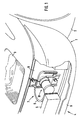
- a sporty two-seater passenger car 1 with a left front wheel 2 and a left headlight 3 has at its front end only a partially shown front bumper 4 with a horizontal bumper 5 that extends essentially transversely to the vehicle longitudinal direction and that is fitted with a bumper cover 6 is provided.
- the bumper 5 is fastened to the vehicle body 8 with left and right bumper brackets 7, only the left of which is shown.
- the bumper bracket 7 is formed by a spring element 9, which is designed as an essentially oval ring with a vertical axis and consists of fiber-reinforced plastic.
- This spring element 9 is fastened on the one hand to the bumper 5 and on the other hand to the vehicle body 8, for example a vehicle side member. It not only serves to absorb shocks up to the first threshold value, that is to say an impact speed of 8 km / h, for example, but also to hold the bumper 5.
- a baffle tube device 10 is arranged at least approximately centrally in the spring element 9 both in the vertical and in the horizontal direction.
- This has an outer baffle tube 11 and an inner baffle tube 12 (Fig. 2, 3). These are designed as round tubes and coaxial to each other with a radial distance from each other arranged such that its longitudinal axis extends at least approximately in the longitudinal direction of the vehicle and thus in the direction of travel.
- the baffle tubes 11, 12, each of which has been divided into the required length by an extruded tube, consist of at least one fiber composite material with fibers oriented at least essentially in the longitudinal direction of the tube. There are no circumferential fibers in the impingement tube walls. For example, glass fibers, carbon fibers or aramid fibers can be used as fibers.
- the outer baffle tube 11 has a greater wall thickness than the inner baffle tube 12.
- the baffle tubes 11, 12 are dimensioned such that their kink length is not reached.
- the front ends of the impingement tubes 11, 12 in the direction of travel are arranged flush with one another at a distance from the part of the spring element 9 on the bumper side. With these ends, the baffle tubes 11, 12 engage in axial annular grooves of a baffle plate 13 carried by the baffle tubes 11, 12.
- the impingement tubes 11, 12 are held on a holding element 14, which has a substantially vertical longitudinal extension, engages around the part of the spring element 9 on the vehicle body side and with the aid of two screws, one of which is above and one below Spring element 9 is arranged, is attached to the front end of one of the side members 15 of the vehicle body 8.
- the holding element 14 has an annular outer deflection plate 16 which extends essentially in the radial direction and one to the front pointing retaining ring 17.
- the front of the outer baffle plate 16 forms an outer baffle 18 with a rounded gradual transition to the outside of the retaining ring 17 in its radially inner region.
- the retaining ring 17 is enclosed by the rear end of the outer impingement tube 11 pushed onto the retaining ring 17, the end face of which is at such a distance from the outer baffle plate 16 that the rear end of the retaining ring 17, in which the outside diameter is due to the gradual transition to the baffle plate 16 increases towards this, is not covered by the outer baffle tube 11.
- the rear end of the outer baffle tube 11 is surrounded by a support ring 19 which bears against the deflection surface 18 with narrow support feet distributed over the circumference in the circumferential direction.
- the holding element 14 projects with a cup-shaped extension through an opening in the part of the spring element 9 on the vehicle body side and into the front end of the longitudinal member 15.
- the end wall of the extension 20 forms an inner deflection plate 21.
- a circumferential axial groove is provided on its front side, which forms an inner deflection surface 22 which has a rounded portion in its radially outer region, which gradually transitions to both the cylindrical wall of the extension 20 and also connects to an at least approximately flat end region of the inner deflecting surface 22. This is followed radially further inward by a further rounding with a gradual transition, which ends at the central region of the inner baffle plate 21 pointing forward in the direction of travel.
- the cylindrical wall of the extension 20 encloses the rear end of the inner baffle tube 12 inserted into the extension 20, the end face of which is at a distance from the inner baffle plate 21 such that the inner one Deflection surface 22 is not covered by the inner baffle tube 12.
- the baffle tubes 11, 12 can be held by a press fit on the retaining ring 17 or in the neck 20. However, their position can also be fixed by additional means. For example, an adhesive binding can be provided.
- the edge of the holding element 14 is bent forward by 90 ° on the two vertical longitudinal sides and on the upper side, so that a collar 23 projecting forward is formed. This protrudes forward on both sides of the holding element 14 at a lateral distance beyond the outer baffle plate 16.
- the bumper 5 and the spring elements 9 carrying the bumper 5 initially deform elastically.
- the first threshold value of, for example, 8 km / h this elastic deformation and its regression remain.
- the inside of the bumper-side part of the spring element 9 lies against the baffle plate 13 and moves it towards the vehicle body 8.
- the outer baffle tube 11 are moved to the outer baffle plate 16 and the inner baffle tube 12 to the inner baffle plate 21.
- the outer baffle tube 11 is widened outwards, specifically because of the diameter that becomes larger on the vehicle body 8 increasing displacement to an increasing extent. The forces acting in the radial direction destroy the outer baffle tube 11.
- the baffle tubes and the spring elements can be easily removed and replaced by new components, so that the vehicle is put back into a ready-to-drive condition.
- the baffle plate 13 strikes the retaining ring 17, the support feet of it bend at one provided on its lower edge Predetermined breaking point.
- the support ring 19 can also be compressed by the baffle plate 13. This ensures that the last remainder of the outer impingement tube 11 is deformed and can contribute to the conversion of the kinetic energy.
- the inner baffle tube 12 is dimensioned such that when the baffle plate 13 approaches the holding element 14 so closely, the space enclosed by the inner baffle tube 12 over the remaining length is completely filled by the deflected wall of the inner baffle tube 12. With further pressure, due to the lack of a possibility of evacuation of this tube wall material, additional fiber breaks occur with further conversion of kinetic energy.
- the force exerted on the longitudinal beams 15 increases in such a way that the vehicle body 8 is also damaged.
- FIGS. 4, 5 differs from that of FIGS. 1 to 3 in that a clamping element 24 made of rubber-elastic material is provided between the part of the spring element 9 on the bumper side and the impact tubes 11, 12.
- the tensioning element 24 is essentially designed as an oval ring with an upright axis and has a baffle plate 25 which receives the front ends of the baffle tubes 11, 12 in axial grooves.
- the tensioning element 24 exercises one Holding force in the direction of the baffles on the holding tubes 11, 12. As a result, these are considered to be a distraction in their standby position.
- the tensioning element 24 ensures that the impact tubes 11, 12 are not loaded with a hard impact, but rather with a gradually increasing force by the part of the spring element 9 on the bumper side.
- the body-side spring element 27 is connected to the side member 26.
- the other spring element 27, which is fastened to the body-side spring element 27, is connected to a bumper 28.
- a baffle tube 29 is arranged, the axis of which extends essentially in the longitudinal direction of the vehicle and thus in the direction of travel, and the structure of which corresponds to that of the baffle tubes 11, 12 of the exemplary embodiments according to FIGS. 1 to 5.
- the baffle tube 29 accordingly also consists of glass fiber reinforced plastic, the fibers of which, however, are not arranged in the circumferential direction as in the case of the spring elements 27, but at least essentially in the longitudinal direction of the tube.
- the body end of the baffle tube 29 is clamped on the side member 26.
- the other end of the baffle tube 29 is arranged at a distance from the bumper 28 in its path of movement.
- the baffle tube 29 carries a baffle plate 30, which projects into the baffle tube 29 with a short cylindrical extension and is glued to it.
- the baffle 30 has a rounded deflection surface which extends from the cylindrical extension to a flat collar surface which extends in the radial direction.
- the outer diameter of the baffle plate 30 is larger than the outer diameter of the baffle tube 29.
- the baffle plate 30 carries a vulcanized rubber buffer 31 on the cylindrical extension.
- a support ring (not shown) surrounds the baffle tube 29 at its end region on the bumper.
- the bumper 28 is provided with a stiffener 32 at the impact point opposite the impact tube 29.
- the bumper 28 hits the deflection plate 30 and presses it into the baffle tube 29.
- the tube wall is deflected radially outwards.
- the support ring prevents the baffle tube 29 from tearing open beyond the deflection area in the axial direction.
- baffle tube next to the spring elements or other resilient fastening means enables a largely free arrangement and dimensioning of the baffle tube.
- the length of the baffle tube is not tied to the dimensions of the spring element.
- a tube wall is deflected inwards along a path with a constant curvature, that is to say along part of a circular path.
- the deflection takes place up to a renewed direction from the tube wall in an approximately axial direction.
- an outward deflection is also provided along a path with constant curvature, that is, along part of a circular path. The deflection does not take place until the deflected wall parts are completely aligned in the radial direction.
- the deflection that is favorable for the respective application can be determined by choosing the curvature or the inclined surface inclination.
- baffle tubes can be arranged one inside the other, but also next to one another.
- a bumper according to the invention can be used both at the front or rear end of the vehicle and at both ends of the vehicle. Instead of forming on one of the baffle tube ends, one can be provided on both baffle tube ends.
Landscapes
- Engineering & Computer Science (AREA)
- General Engineering & Computer Science (AREA)
- Mechanical Engineering (AREA)
- Vibration Dampers (AREA)
Claims (18)
- Pare-chocs pour véhicules automobiles, en particulier voitures particulières, avec une barre de parechocs (5, 28), avec des moyens de fixation souples (9, 27), grâce auxquels la barre de choc (5, 28) est maintenue sur la carrosserie (8) du véhicule à une distance changeable de celle-ci et gui peuvent être régénérés essentiellement lors de modifications de cette distance dans une première zone d'écartement, et avec des tubes de choc (11, 12, 29) dont les axes s'étendent essentiellement dans le sens longitudinal du véhicule et qui sont réalisés comme des pièces spéciales des moyens de fixation souples et ils sont mis en action en tant que moyens d'appui, lors de raccourcissements de la distance dans une deuxième zone d'écartement, qui est située plus proche que la première zone par rapport à la carrosserie du véhicule (8), par suite d'une charge de compression dans le sens longitudinal du tube et ils ne sont pas régénérables sous l'effet d'une déviation du matériau de paroi du tube dans le sens transversal,
caractérisé en ce que,
les tubes de choc (11, 12, 29) sont composés au moins d'une matière composite renforcée par des fibres, et les fibres de cette matière composite sont disposées dans le sens longitudinal du tube et la déviation du matériau de la paroi du tube a lieu par destruction côté extrémité du tube, de la paroi du tube. - Pare-chocs selon la revendication 1, caractérisé en ce que les tubes de choc (11, 12, 29) sont produits en profilés par étirage mécanique.
- Pare-chocs selon la revendication 1 ou 2, caractérisé en ce qu'on utilise comme fibres des tubes de choc (11, 12, 29) des fibres de verre, des fibres de carbone ou des fibres d'aramide.
- Pare-chocs selon les revendications 1, 2 ou 3, caractérisé en ce que comme matière de matrice des tubes de choc (11, 12, 29) on utilise au moins une matière du groupe des résines époxy, des résines de polyester, des résines de phénol ou des résines d'ester vinylique.
- Pare-chocs selon les revendications 1, 2 ou 3, caractérisé en ce que comme matière de matrice des tubes de choc (11, 12, 29) on utilise au moins une matière thermoplastique.
- Pare-chocs selon une des revendications 1 à 5, caractérisé en ce qu'au moins sur une des extrémités de chaque tube de choc (11, 12, 29) est placée une plaque de déviation (16, 21, 30), qui comporte une surface de déviation (18, 22).
- Pare-chocs selon la revendication 6, caractérisé en ce que la surface de déviation (18, 22) est réalisée arrondie.
- Pare-chocs selon une des revendications 1 à 7, caractérisé en ce qu'une déviation de la paroi de tube est prévue-vers l'intérieur.
- Pare-chocs selon une des revendications 1 à 7, caractérisé en ce qu'une déviation de la paroi de tube est prévue vers l'extérieur, et les tubes de choc (11) sont entourés au voisinage de l'extrémité de déviation par un anneau d'appui (19).
- Pare-chocs selon une des revendications 1 à 9, caractérisé en ce qu'une déviation de paroi de tube d'au moins une partie de la paroi des tubes est prévue au moins approximativement de 180°
- Pare-chocs selon une des revendications 1 à 10, caractérisé en ce que les tubes de choc (11, 12) sont disposés l'un dans l'autre.
- Pare-chocs selon la revendication 11, caractérisé en ce que les tubes de choc (11, 12) sont disposés coaxialement l'un par rapport à l'autre.
- Pare-chocs selon la revendication 12, caractérisé en ce qu'entre les tubes de choc (11, 12) disposés coaxialement l'un par rapport à l'autre est prévu tout autour un intervalle dans le sens transversal.
- Pare-chocs selon les revendications 11, 12 ou 13, caractérisé en ce qu'une déviation de la paroi de tube est prévue aussi bien vers l'intérieur que vers l'extérieur.
- Pare-chocs selon une des revendications 1 à 14, caractérisé en ce que comme moyens de fixation souples sont prévus essentiellement des éléments élastiques (9, 27) réalisés en forme d'anneaux constitués de matière renforcée de fibres, qui sont chargés dans le sens transversal de l'anneau et sont régénérables élastiquement dans la première zone d'écartement et lors de diminutions de la distance dans la deuxième zone d'écartement ils sont opérationnels également comme éléments de choc essentiellement non régénérables sous l'effet de destruction.
- Pare-chocs selon la revendication 15, caractérisé en ce qu'au moins un tube de choc (11, 12) est disposé dans un élément élastique (9).
- Pare-chocs selon la revendication 16, caractérisé en ce qu'au moins l'un des tubes de choc (11, 12) est maintenu par au moins un élément de tension (24) dans l'élément élastique (9).
- Pare-chocs selon la revendication 15, caractérisé en ce que les tubes de choc (29) sont disposés en dehors des éléments élastiques (27) à côté de ceux-ci dans leur voisinage.
Applications Claiming Priority (2)
| Application Number | Priority Date | Filing Date | Title |
|---|---|---|---|
| DE3833048 | 1988-09-29 | ||
| DE3833048A DE3833048C2 (de) | 1988-09-29 | 1988-09-29 | Stoßfänger für Kraftfahrzeuge, insbesondere Personenkraftwagen |
Publications (2)
| Publication Number | Publication Date |
|---|---|
| EP0361343A1 EP0361343A1 (fr) | 1990-04-04 |
| EP0361343B1 true EP0361343B1 (fr) | 1994-11-30 |
Family
ID=6363962
Family Applications (1)
| Application Number | Title | Priority Date | Filing Date |
|---|---|---|---|
| EP89117626A Expired - Lifetime EP0361343B1 (fr) | 1988-09-29 | 1989-09-23 | Pare-chocs pour véhicules automobiles, en particulier pour voitures |
Country Status (4)
| Country | Link |
|---|---|
| US (1) | US5116092A (fr) |
| EP (1) | EP0361343B1 (fr) |
| DE (2) | DE3833048C2 (fr) |
| WO (1) | WO1993014954A1 (fr) |
Families Citing this family (49)
| Publication number | Priority date | Publication date | Assignee | Title |
|---|---|---|---|---|
| JPH04303046A (ja) * | 1991-03-29 | 1992-10-27 | Aisin Seiki Co Ltd | 車両用バンパ装置 |
| US5273330A (en) * | 1992-11-23 | 1993-12-28 | General Motors Corporation | Twist-lock mounting assembly and method for a bumper energy absorber |
| DE19522575C2 (de) * | 1994-06-27 | 1999-06-10 | Lw Composite Gmbh & Co | Aufprallvorrichtung für Fahrzeuge |
| GB2307665B (en) * | 1995-11-30 | 1999-04-14 | Rover Group | An impact absorbing structure for a motor vehicle |
| GB2308100B (en) * | 1995-12-14 | 1999-09-01 | Rover Group | A motor vehicle and an energy absorbing structure therefor |
| DE19627061C2 (de) * | 1996-07-05 | 1998-01-29 | Audi Ag | Deformationselement |
| BE1010760A3 (fr) * | 1996-11-22 | 1999-01-05 | Solvay | Dispositif anti-choc. |
| DE19717473B4 (de) * | 1997-04-25 | 2006-01-12 | Bombardier Transportation Gmbh | Energieabsorberelement |
| FR2763547A1 (fr) * | 1997-05-23 | 1998-11-27 | Plastic Omnium Cie | Pare-chocs a absorbeur local |
| DE19736803C2 (de) * | 1997-08-23 | 1999-07-01 | Audi Ag | Deformationselement |
| US6179355B1 (en) * | 1998-12-18 | 2001-01-30 | Ford Global Technologies, Inc. | Automotive vehicle bumper assembly |
| US6969084B2 (en) * | 1999-04-26 | 2005-11-29 | Ford Global Technologies Inc. | Automotive bumper with integral hitch cover |
| US6581955B2 (en) | 1999-04-26 | 2003-06-24 | Ford Global Technologies, L.L.C. | Tow hitch rear bumper assembly |
| US6179320B1 (en) | 1999-04-26 | 2001-01-30 | Ford Global Technologies, Inc. | Tow hitch rear bumper assembly |
| DE19943621B4 (de) * | 1999-09-11 | 2006-06-01 | Audi Ag | Deformationselement für Kraftfahrzeuge |
| DE19943622B4 (de) * | 1999-09-11 | 2006-06-01 | Audi Ag | Dämpfungselement für Kraftfahrzeuge |
| US6485072B1 (en) | 1999-12-15 | 2002-11-26 | Ford Global Technologies, Inc. | Bumper system for motor vehicles |
| US6231095B1 (en) * | 1999-12-23 | 2001-05-15 | Benteler Automotive Corporation | Energy absorption impact system |
| US6412836B1 (en) | 2000-10-11 | 2002-07-02 | Ford Global Technologies, Inc. | Bumper system for motor vehicles |
| US7155049B2 (en) | 2001-01-11 | 2006-12-26 | Trestle Acquisition Corp. | System for creating microscopic digital montage images |
| US6409239B1 (en) | 2001-04-17 | 2002-06-25 | Benteler Automotive Corporation | Energy absorption impact system and method for making the same |
| USD468674S1 (en) | 2001-08-16 | 2003-01-14 | Ford Global Technologies, Inc. | Vehicle hitch cover assembly |
| US6520360B1 (en) | 2001-10-19 | 2003-02-18 | Miner Enterprises, Inc | Housing for draft gear |
| DE10159067A1 (de) | 2001-12-01 | 2003-06-26 | Daimler Chrysler Ag | Faserverbund-Crashstruktur |
| FR2837762B1 (fr) * | 2002-03-26 | 2004-12-10 | Valeo Thermique Moteur Sa | Poutre pare-chocs avec absorbeur d'energie pour vehicule automobile |
| US6601886B1 (en) | 2002-05-31 | 2003-08-05 | Hexcel Corporation | Energy absorbing composite tube |
| DE10243460A1 (de) | 2002-09-19 | 2004-04-01 | Rehau Ag + Co. | Polymerer Energieabsorber für Kraftfahrzeuge und Stoßfängersystem |
| DE10343431B4 (de) * | 2003-09-19 | 2005-11-17 | Audi Ag | Deformationselement |
| GB2422136B (en) * | 2005-01-12 | 2007-03-14 | Lotus Car | A bumper assembly for an automobile |
| US9012390B2 (en) * | 2006-08-07 | 2015-04-21 | Raindance Technologies, Inc. | Fluorocarbon emulsion stabilizing surfactants |
| US7866716B2 (en) | 2008-04-08 | 2011-01-11 | Flex-N-Gate Corporation | Energy absorber for vehicle |
| ATE507128T1 (de) | 2009-09-15 | 2011-05-15 | Voith Patent Gmbh | ENERGIEVERZEHRVORRICHTUNG, INSBESONDERE IN GESTALT EINER STOßSICHERUNG FÜR EIN SPURGEFÜHRTES FAHRZEUG |
| DE102009056873A1 (de) | 2009-12-03 | 2010-07-22 | Daimler Ag | Deformationselement und dessen Anordnung an einer Karosserie |
| US8182023B2 (en) | 2010-03-16 | 2012-05-22 | Sabic Innovative Plastics Ip B.V. | Plastically deformable spring energy management systems and methods for making and using the same |
| FR2958226B1 (fr) * | 2010-04-06 | 2012-10-19 | Akka Ingenierie Produit | Chassis pour vehicule electrique |
| DE102011008867B4 (de) * | 2011-01-18 | 2013-03-14 | Leichtbau-Zentrum Sachsen Gmbh | Vorrichtung zur Umwandlung von Aufprallenergie |
| US8827352B2 (en) * | 2012-02-29 | 2014-09-09 | GM Global Technology Operations LLC | Bumper retention system |
| FR2988150B1 (fr) | 2012-03-14 | 2018-03-16 | Centre Technique Des Industries Mecaniques | Boite-tampon d'absorption d'energie |
| JP5791676B2 (ja) * | 2013-09-10 | 2015-10-07 | 富士重工業株式会社 | 衝撃吸収装置 |
| FR3010672B1 (fr) * | 2013-09-17 | 2016-09-30 | Centre Technique Des Ind Mec | Ensemble d'absorption d'energie de choc |
| CN103661183B (zh) * | 2013-12-12 | 2016-10-26 | 东华大学 | 一种车用混杂型复合材料能量吸收部件及其生产方法 |
| DE102014001232B4 (de) * | 2014-01-29 | 2019-01-24 | Audi Ag | Trägerprofil für eine Fahrzeugkarosserie mit unterschiedlichen Versagensmodi |
| DE102014101186A1 (de) * | 2014-01-31 | 2015-08-06 | GEDIA Gebrüder Dingerkus GmbH | Stoßfänger für ein Kraftfahrzeug |
| JP6521290B2 (ja) * | 2015-02-19 | 2019-05-29 | 株式会社Subaru | エネルギ吸収部材の保持構造 |
| US10065587B2 (en) | 2015-11-23 | 2018-09-04 | Flex|N|Gate Corporation | Multi-layer energy absorber |
| CN105599716B (zh) * | 2016-01-27 | 2017-09-29 | 奇瑞汽车股份有限公司 | 一种汽车吸能盒及其使用方法 |
| FR3116247A1 (fr) * | 2020-11-18 | 2022-05-20 | Valeo Systemes Thermiques | Ensemble absorbeur d’énergie de choc |
| EP4517129A1 (fr) * | 2023-09-01 | 2025-03-05 | Valeo Systemes Thermiques | Structure d'absorption de choc, notamment pour vehicule automobile |
| FR3152476A1 (fr) * | 2023-09-01 | 2025-03-07 | Valeo Systemes Thermiques | Structure d’absorption de choc, notamment pour véhicule automobile |
Family Cites Families (15)
| Publication number | Priority date | Publication date | Assignee | Title |
|---|---|---|---|---|
| DE7129356U (de) * | 1973-11-22 | Muhr Und Bender | Stoßstangenhalter | |
| GB202780A (en) * | 1922-06-14 | 1923-08-30 | John Little | Improvements in centrifugal pumps |
| US3428150A (en) * | 1966-12-28 | 1969-02-18 | Paul M Muspratt | Method and apparatus for gradual absorption of momentum |
| US3608677A (en) * | 1968-10-03 | 1971-09-28 | North American Rockwell | Fragmenting tube energy absorber |
| US3663048A (en) * | 1970-04-03 | 1972-05-16 | Gen Motors Corp | Vehicle bumper installation |
| DE2262293C3 (de) * | 1972-12-20 | 1980-12-04 | Dr.Ing.H.C. F. Porsche Ag, 7000 Stuttgart | Stoßenergie absorbierendes Deformationselement für Kraftfahrzeuge, insbesondere Personenkraftwagen |
| US3912295A (en) * | 1974-03-04 | 1975-10-14 | Budd Co | Crash energy-attenuating means for a vehicle frame construction |
| DE2441557A1 (de) * | 1974-08-30 | 1976-03-11 | Messerschmitt Boelkow Blohm | Anordnung zur abstuetzung eines stossfaengers |
| CA1107769A (fr) * | 1978-05-10 | 1981-08-25 | Henry E. Wilson | Amortisseur tubulaire composite fait de fibres |
| FR2464871A1 (fr) * | 1979-09-07 | 1981-03-20 | Renault | Structure d'extremite a absorption d'energie pour vehicules automobiles |
| DE3049425C2 (de) * | 1980-12-30 | 1991-09-05 | Messerschmitt-Bölkow-Blohm GmbH, 8000 München | Aufprall-Schutz-Bauteil |
| GB2134211B (en) * | 1983-01-31 | 1986-06-04 | Nat Res Dev | Kinetic energy absorber |
| GB2152181B (en) * | 1983-12-29 | 1987-07-29 | Cranfield Inst Of Tech | Shock absorbers absorbing energy by permanent deformation |
| JPS6217438A (ja) * | 1985-07-16 | 1987-01-26 | Nippon Koukuuki Kaihatsu Kyokai | 圧縮エネルギ−吸収部材 |
| DE3626150A1 (de) * | 1986-08-01 | 1988-02-18 | Bayerische Motoren Werke Ag | Stossfaenger fuer kraftfahrzeuge, insbesondere personenkraftwagen |
-
1988
- 1988-09-29 DE DE3833048A patent/DE3833048C2/de not_active Expired - Fee Related
-
1989
- 1989-09-23 US US07/663,820 patent/US5116092A/en not_active Expired - Fee Related
- 1989-09-23 EP EP89117626A patent/EP0361343B1/fr not_active Expired - Lifetime
- 1989-09-23 WO PCT/EP1989/001110 patent/WO1993014954A1/fr not_active Ceased
- 1989-09-23 DE DE58908685T patent/DE58908685D1/de not_active Expired - Fee Related
Also Published As
| Publication number | Publication date |
|---|---|
| US5116092A (en) | 1992-05-26 |
| DE3833048C2 (de) | 1994-03-24 |
| WO1993014954A1 (fr) | 1993-08-05 |
| DE58908685D1 (de) | 1995-01-12 |
| EP0361343A1 (fr) | 1990-04-04 |
| DE3833048A1 (de) | 1990-04-05 |
Similar Documents
| Publication | Publication Date | Title |
|---|---|---|
| DE3833048C2 (de) | Stoßfänger für Kraftfahrzeuge, insbesondere Personenkraftwagen | |
| DE19717473B4 (de) | Energieabsorberelement | |
| DE4317738C2 (de) | Energieabsorber | |
| EP0364432B1 (fr) | Amortisseur de choc pour véhicules automobiles | |
| DE2610001C2 (de) | Vorrichtung zum Absorbieren von Energie | |
| DE69104216T2 (de) | Bugteil für ein kraftfahrzeug. | |
| DE19700022A1 (de) | Stoßfängeranordnung für Kraftfahrzeuge | |
| EP0850807B1 (fr) | Dispositif d'absorption d'énergie pour véhicule automobile | |
| DE19627061C2 (de) | Deformationselement | |
| DE4238631C2 (de) | Verfahren zum Montieren einer Stoßverzehrvorrichtung | |
| EP0476288A1 (fr) | Galerie de toit pour véhicules automobiles | |
| EP0246397B1 (fr) | Ensemble déformable de montage d'un pare-choc sur le chassis d'un véhicule | |
| EP0909682B1 (fr) | Amortisseur de chocs pour véhicule automobile | |
| EP1541424B1 (fr) | Un élément d'absorption de choc en form profilé creux | |
| DE3626150A1 (de) | Stossfaenger fuer kraftfahrzeuge, insbesondere personenkraftwagen | |
| DE19526119C2 (de) | Stoßenergieabsorptionseinrichtung | |
| DE4300284C2 (de) | Pralldämpfer | |
| DE2422479C2 (de) | Pralldämpfer mit Kraftbegrenzung | |
| DE3839976C2 (fr) | ||
| DE102016201733A1 (de) | Stoßdämpfer-Baugruppe für ein Kraftfahrzeug | |
| DE102009008674B4 (de) | Karosseriestruktur eines Fahrzeugs | |
| WO1998038438A2 (fr) | Element servant a absorber l'energie cinetique | |
| WO2002018816A1 (fr) | Dispositif pour absorber l'energie de choc | |
| DE29916520U1 (de) | Fahrzeugstoßfänger | |
| EP0589227A1 (fr) | Dispositif de protection contre les accidents monté sur véhicules |
Legal Events
| Date | Code | Title | Description |
|---|---|---|---|
| PUAI | Public reference made under article 153(3) epc to a published international application that has entered the european phase |
Free format text: ORIGINAL CODE: 0009012 |
|
| AK | Designated contracting states |
Kind code of ref document: A1 Designated state(s): DE ES FR GB IT SE |
|
| 17P | Request for examination filed |
Effective date: 19900507 |
|
| 17Q | First examination report despatched |
Effective date: 19920706 |
|
| RAP3 | Party data changed (applicant data changed or rights of an application transferred) |
Owner name: BAYERISCHE MOTOREN WERKE AKTIENGESELLSCHAFT |
|
| GRAA | (expected) grant |
Free format text: ORIGINAL CODE: 0009210 |
|
| AK | Designated contracting states |
Kind code of ref document: B1 Designated state(s): DE ES FR GB IT SE |
|
| PG25 | Lapsed in a contracting state [announced via postgrant information from national office to epo] |
Ref country code: ES Free format text: THE PATENT HAS BEEN ANNULLED BY A DECISION OF A NATIONAL AUTHORITY Effective date: 19941130 |
|
| ET | Fr: translation filed | ||
| GBT | Gb: translation of ep patent filed (gb section 77(6)(a)/1977) |
Effective date: 19941208 |
|
| REF | Corresponds to: |
Ref document number: 58908685 Country of ref document: DE Date of ref document: 19950112 |
|
| ITF | It: translation for a ep patent filed | ||
| PG25 | Lapsed in a contracting state [announced via postgrant information from national office to epo] |
Ref country code: SE Effective date: 19950228 |
|
| PLBE | No opposition filed within time limit |
Free format text: ORIGINAL CODE: 0009261 |
|
| STAA | Information on the status of an ep patent application or granted ep patent |
Free format text: STATUS: NO OPPOSITION FILED WITHIN TIME LIMIT |
|
| 26N | No opposition filed | ||
| PGFP | Annual fee paid to national office [announced via postgrant information from national office to epo] |
Ref country code: DE Payment date: 19960909 Year of fee payment: 8 |
|
| PGFP | Annual fee paid to national office [announced via postgrant information from national office to epo] |
Ref country code: GB Payment date: 19960919 Year of fee payment: 8 |
|
| PGFP | Annual fee paid to national office [announced via postgrant information from national office to epo] |
Ref country code: FR Payment date: 19960930 Year of fee payment: 8 |
|
| PG25 | Lapsed in a contracting state [announced via postgrant information from national office to epo] |
Ref country code: GB Free format text: LAPSE BECAUSE OF NON-PAYMENT OF DUE FEES Effective date: 19970923 |
|
| PG25 | Lapsed in a contracting state [announced via postgrant information from national office to epo] |
Ref country code: FR Free format text: THE PATENT HAS BEEN ANNULLED BY A DECISION OF A NATIONAL AUTHORITY Effective date: 19970930 |
|
| GBPC | Gb: european patent ceased through non-payment of renewal fee |
Effective date: 19970923 |
|
| PG25 | Lapsed in a contracting state [announced via postgrant information from national office to epo] |
Ref country code: DE Free format text: LAPSE BECAUSE OF NON-PAYMENT OF DUE FEES Effective date: 19980603 |
|
| REG | Reference to a national code |
Ref country code: FR Ref legal event code: ST |
|
| PG25 | Lapsed in a contracting state [announced via postgrant information from national office to epo] |
Ref country code: IT Free format text: LAPSE BECAUSE OF NON-PAYMENT OF DUE FEES;WARNING: LAPSES OF ITALIAN PATENTS WITH EFFECTIVE DATE BEFORE 2007 MAY HAVE OCCURRED AT ANY TIME BEFORE 2007. THE CORRECT EFFECTIVE DATE MAY BE DIFFERENT FROM THE ONE RECORDED. Effective date: 20050923 |