EP0361369A2 - Einsatz für einen Schleuersitz mit einer Kopfstütze bzw. Rückgratentlastung - Google Patents
Einsatz für einen Schleuersitz mit einer Kopfstütze bzw. Rückgratentlastung Download PDFInfo
- Publication number
- EP0361369A2 EP0361369A2 EP89117690A EP89117690A EP0361369A2 EP 0361369 A2 EP0361369 A2 EP 0361369A2 EP 89117690 A EP89117690 A EP 89117690A EP 89117690 A EP89117690 A EP 89117690A EP 0361369 A2 EP0361369 A2 EP 0361369A2
- Authority
- EP
- European Patent Office
- Prior art keywords
- back plate
- seat
- spine
- head support
- support member
- Prior art date
- Legal status (The legal status is an assumption and is not a legal conclusion. Google has not performed a legal analysis and makes no representation as to the accuracy of the status listed.)
- Granted
Links
Images


Classifications
-
- A—HUMAN NECESSITIES
- A42—HEADWEAR
- A42B—HATS; HEAD COVERINGS
- A42B3/00—Helmets; Helmet covers ; Other protective head coverings
- A42B3/04—Parts, details or accessories of helmets
- A42B3/0406—Accessories for helmets
- A42B3/0473—Neck restraints
-
- B—PERFORMING OPERATIONS; TRANSPORTING
- B64—AIRCRAFT; AVIATION; COSMONAUTICS
- B64D—EQUIPMENT FOR FITTING IN OR TO AIRCRAFT; FLIGHT SUITS; PARACHUTES; ARRANGEMENT OR MOUNTING OF POWER PLANTS OR PROPULSION TRANSMISSIONS IN AIRCRAFT
- B64D25/00—Emergency apparatus or devices, not otherwise provided for
- B64D25/02—Supports or holding means for living bodies
-
- B—PERFORMING OPERATIONS; TRANSPORTING
- B64—AIRCRAFT; AVIATION; COSMONAUTICS
- B64D—EQUIPMENT FOR FITTING IN OR TO AIRCRAFT; FLIGHT SUITS; PARACHUTES; ARRANGEMENT OR MOUNTING OF POWER PLANTS OR PROPULSION TRANSMISSIONS IN AIRCRAFT
- B64D25/00—Emergency apparatus or devices, not otherwise provided for
- B64D25/08—Ejecting or escaping means
- B64D25/10—Ejector seats
Definitions
- This invention relates to restraint systems and seat systems and more particularly to a seat insert, insertable within the existing seat of a vehicle, for protecting the crew member of the vehicle from high "G" accelerations resulting from aircraft maneuvers and/or emergency ejections from the aircraft.
- G-LOC G-induced Loss of Consciousness
- Aircraft equipment malfunction or adverse environmental conditions may occasionally make proper control of the aircraft so difficult as to render it improbable that the aircraft can be safely landed.
- Enemy fire in combat situations may seriously disable an aircraft or crew member making it also improbable that the aircraft can be brought to a safe landing. In such situations, ejection of the crew members from the aircraft may be desirable.
- the high forces of acceleration generated by catapult ejection systems may be added to the forces generated by the motion of the aircraft and the total forces may thus exceed the tolerance of the crew members. Consequently, pilots and their crew members are occasionally killed or severely disabled as a result of ejection from an aircraft.
- the invention utilizes a helmet that rotates on a track and in an inertia reel, which will lock when lateral forces exceed predetermined levels.
- U. S. Patent Serial No. 865,508 to E. A. Smith, B. J. Courter, and S. G. Wurst, entitled "Forward Posture Support Seat System” (also assigned to Rockwell International Corporation) discloses a restraint system which helps provide protection against the compression of the vertebrae of the spine caused by high G-induced forces resulting from ejection from the aircraft as well as aircraft maneuvers.
- the invention utilizes a seat insert which is rotatably connected to the seat to provide multi-axis rotation (allows crew member to turn in the seat). Such a rotation is provided by a ball-type joint and telescoping strut.
- the Smith patent also teaches use of a strap harness which secures the crew member to the seat back; an inertia reel; and torso support means, which is lockable when the crew member is in a crouched over position such that fore and aft motion of the crew member is substantially precluded.
- a strap harness which secures the crew member to the seat back
- an inertia reel which is lockable when the crew member is in a crouched over position such that fore and aft motion of the crew member is substantially precluded.
- a seat system is thus needed that will provide protection against the compression of the vertebrae of the spine caused by high forces of acceleration resulting from ejection from the aircraft, as well as aircraft maneuvers, while still allowing sufficient pilot mobility, good visibility, and good access to the controls.
- Yet another object is to provide a seat insert which requires minimal modification to the existing aircraft seat and cockpit structure.
- Still another object of the present invention is to provide a seat insert G protection system with minimal don/doff requirements for easy ingress and rapid emergency egress.
- Another object is to provide a seat insert with minimal interconnectability with the existing ejection seat; thereby, ensuring rapid positive separation of the seat insert from the seat during the seat/man separation phase of ejection and escape.
- Yet another object of the present invention is to provide a seat insert which is integrated with the crew member parachute harness system and allows unimpeded body positioning for parachute opening shock and crew member leg extension for parachute landing.
- the present invention is a seat insert insertable within the existing seat of a vehicle for maintaining a crew member of the vehicle in a forward posture during high-G acceleration.
- the invention comprises an elongated head support member for supporting the crew member's head during a forward leaning posture; a back plate assembly including at least one back plate connected to the head support member for supporting the spine in its natural curvature; means being connected to the back plate assembly for pivoting the back plate assembly forward relative to the seat of the vehicle; means for transfering any G-induced weight from the spine to the back plate assembly and ultimately to the existing seat of the vehicle; and means for restraining the head support member in such a manner so as to maintain the crew member's head in an "eyes up" attitude during a forward lean.
- the back plate assembly includes a thoracic back plate and a lumbar back plate each having substantially the same curvature as its respective portion of the spine and being attached in a manner that provides relative yaw motion therebetween.
- the means for restraining the head support member in an "eyes up" attitude includes a head support member restraint cord connected at a top end to the head support member and at a bottom end to a fixed point which does not articulate forward with the back plate assembly. In a preferred embodiment this fixed point is located on a seat pan base assembly which is contoured to fit upon the seat of the vehicle and about the crew member's buttocks.
- the seat pan base assembly includes means for pivotly connecting the seat pan base assembly to hip extensions extending from the back plate assembly, thereby allowing transference of G-induced loads from the hip extensions to the seat pan base assembly.
- the restraint cord has sufficient length to restrain the head support member movement during a crew member's forward lean.
- the seat insert of the present invention reduces the risk of spinal injury by off-loading the pilot's spine and supporting the spine in its natural curvature, thereby preventing (1) harmful bending of the spine, and (2) non-uniform load distribution across individual vertebrae interfaces, both situations of which are known to cause spinal injury during high-G manuevering and ejection.
- the crew member experiences G-induced or increased body weight. This causes the crew member's body to become heavy and sink into the seat. This "sinking" of the body and head serves to compress the spine.
- the present invention aids in alleviating this problem by allowing the crew member to firmly secure himself between the back plate assembly and a chest plate, thereby, preventing excessive sinking of the body and compression of the spine in the G-induced environment, and by providing a head support system which aids in restraining the head up off of the spine in the G-induced environment. Since the invention serves to hold the body up in the G-induced environment, it effectively serves to off load the crew member's spine by transfering the G-induced body weight through the back plate assembly to the hip extensions, and ultimately to the seat structure.
- Fig. 1 illustrates a pilot 10 wearing a restraint harness generally designated 12 of a type typically utilized by pilots in fighter aircraft.
- the restraint harness 12 is used to help secure the pilot in the seat as described below and to allow connection with a parachute.
- the harness 12 includes shoulder straps 14 which extend around the back and down the chest.
- the shoulder straps 14 are linked by a cross strap 16 extending across the lower chest or upper abdomen.
- Leg straps 18 are also provided to maintain the necessary support required for ejection with a parachute.
- the restraint harness 12 aids in securing a two-piece chest plate 20 which insures uniform distribution of loads over the crew member's rib cage while undergoing high G-induced forces during a forward lean.
- the seat insert 22 includes an elongated head support member 24 for supporting the crew member's head during a forward leaning posture.
- a head support member restraint cord 25 is provided to restrain head support member 24 movement during a crew member forward lean.
- the lower end of the head support member 24 is connected to the upper end of a thoracic back plate 26 by a cervical spring 28.
- the cervical spring 28 biases the head support member 24 toward a forward position, as explained in more detail below.
- the thoracic back plate 26 has a front surface with substantially the same curvature as the thoracic spine of the crew member.
- Two forwardly extending hip extensions 32, each integral with (or rigidly connected to) a respective side of the lumbar back plate 30 are provided for lateral hip support and for securing the lumbar back plate 30 to a seat pan base assembly 34 which is contoured to fit on the seat pan of the vehicle and about the crew member's buttocks.
- the seat pan base assembly 34 includes a seat pan base 36 having lateral upwardly extending projections or receptors 38 which are connected to the hip extensions by pivoting pin joints 40.
- the seat pan base assembly 34 also includes a pelvic support wedge 42 located between the seat pan base 36 and the lumbar back plate 30 and hinged to the aft end of the seat pan base 36.
- a pair of forward extending, fixed, lateral support plates 44 are fixed to the sides of the thoracic back plate 26 (at shoulder height) for maintaining crew member body support during lateral force input.
- Thoracic straps 46 are attached to the thoracic back plate 26 for allowing the cry member 10 to tightly secure himself between a chest plate and the thoracic back plate 26, as described in detail below.
- the thoracic back plate 26, lumbar back plate 30, support wedge 42 and seat pan base 36 each have foam inserts designated 26a, 30a, 42a, and 36a, respectively (preferably formed of polyurethane) for comfort.
- each thoracic strap 46 wraps through a rapid egress snap hook 54 and then through an adjustor 56 attached to the lower end of the thoracic back plate 26.
- the thoracic straps 46 are wrapped around the thorax of the crew member 10 during use and are adjustable so as to allow the crew member to tightly secure himself between a chest plate (described below) and the thoracic back plate 26.
- the straps may be tightened by pulling on ends 58.
- the head support member 24 has a vertical height substantially equal to the height of the seat 48 for not interfering with any cockpit structure external to the seat.
- Fig. 3 also illustrates that shoulder straps 60 (which are not part of the seat insert, itself) extend from inertia reels 62 located in the seat back behind the head support member 24.
- Lap belts 64 also not part of the seat insert, itself are also used to secure the crew member 10 to the seat structure 52.
- a pilot is shown seated on the seat structure 52 with the seat insert 22 attached. It can be seen (i.e. arrows 66) that the straps 60 originating from the inertia reels 62 are attached to buckles 68 on the shoulder straps 14 of restraint harness 12.
- the thoracic straps 46 attach to buckles 70 on the restraint harness 12.
- Arrows 74 illustrate connection of the lap belts 64.
- the forward extending lateral support plates 44 are shown to be adjustable, as denoted by arrows 76, for differing pilot sizes.
- Fig. 5 a side view of the crew member strapped onto the seat insert 22 in an upright position is shown.
- the thoracic straps 46 are oriented at an angle which is as parallel as possible to the pilot's spine to allow the pilot to be effectively "picked up" off of his spine during G-loading.
- Fig. 5 illustrates that the seat pan base assembly 34 includes a knee elevation wedge 78, having an apex at approximately the midpoint of the seat pan base assembly 34 and terminating at a high end at the fore edge of the seat pan base assembly 34 for elevating the legs of the pilot, thereby reducing the total blood "hydrostatic" column.
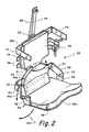
- the novel head support member restraint cord 25 is securably attached at a top end to the head support member 24 and at a bottom end to a housing 80 contiguous with the support wedge 42, 42a and containing another inertia reel 81.
- the housing 80 is schematically illustrated in phantom in Fig. 2.
- the restraint cord 25 is preferably formed of a steel wire or cord.
- the lower portion of the restraint cord 25 is covered by a sheath 82 for limiting exposure of the restraint cord 25.
- the sheath 82 may be formed of plastic, rubber or other resilient material and is anchored at locations 84, 86 to the thoracic back plate 26 and lumbar back plate 30.
- An upper helmet support strap 88 extends from a helmet strap receptor hook 90 secured to the upper end of the head support member 24 for distributing weight off of the cervical spine and for maintaining the head in an "eyes forward" attitude and forward lean.
- a second strap 92 extends from receptor hook 90 to the lower back of the helmet 94 for limiting head/helmet differential rotation.
- Fig. 6 in which the pilot 10 is illustrated in a forward leaning posture.
- the pilot 10 while experiencing high G's the pilot 10 with the seat insert 22 tightly secured thereto has moved forward.
- a small amount of slack (perhaps 2 to 3 inches) which was contained within the inertia reel 81 (not shown in this Figure), which secures the restraint cord 25, is eventually used up.
- the cervical spring 28 serves to bias the head support member 24 toward a forward position keeping the restraint cord 25 taut.
- the pilot's head is tilted up in an "eyes forward" position (for tactical situation awareness) and supported by helmet support straps 88, 92.
- a forehead strap 96 similar to a nape strap is provided to keep the helmet from rotating off the head.
- utilization of the seat insert 22 of the present invention allows the pilot 10 to twist his back (see arrows 97 in Fig. 2) and neck to "check 6 o'clock" as illustrated by arrows 98 in Fig. 7. Furthermore, pilot 10 can look up as illustrated by arrows 100 in Fig. 8 and look down as illustrated by arrows 102 in Fig. 9. In all positions, lateral body movements are restricted by the lateral shoulder support plates 44.
- a pilot 10 wearing a restraint harness 12 goes through his normal cockpit ingress procedures and secures himself to the seat insert 22 with the thoracic straps 46.
- the pilot then connects his lap belt 64 and inertia reel attachment straps 60 and puts on his helmet with forehead strap, chin strap, and positive pressure breathing mask (not shown) attached.
- the pilot is secured to the seat and seat insert systems.
- the pilot can move toward a prescribed distance. This distance is determined by the length of the inertia reel attachment straps 60.
- the back plate assembly i.e. thoracic back plate 26, lumbar back plate 30
- the chest plate 20 remain tightly secured to the pilot's body.
- the back plate assembly 26, 30 rotates forward about the hip flare receptor pivot pins 40.
- the restraint cord 25 eventually loses its slack as the lumbar back plate 30 moves away from the wedge 42. When the slack is completely taken up, the cord 25 will tense and restrain the head support member 24 from further unified motion with the back plates 26, 30.
- the head support member 24 can be maintained (with the proper initial cord length) in a substantially vertical position thus providing the support necessary through the helmet straps 88, 92 to keep the pilot's head in an "eyes forward" attitude for proper, straight ahead field of view.
- the seat insert 22 remains secured to the pilot after seat/man separation.
- the bottom of the wedge 42 contacts the back end of the seat pan base 36 providing a structural link to absorb the high compressive forces associated with ejection normally borne by the back plate system 26, 30 during tactical maneuvers. These forces are distributed back to the seat pan base assembly 34 in the same fashion as described for spine offloading during tactical G-maneuvers. This additional offloading procedure provided for ejection reduces the risk of injury to the spine associated with excessively high ejection acceleration loads.
- the pelvic support wedge 42 is passively mobilized (retracted) in the direction of arrows 106 to allow the seat pan base 36 of the insert to drop down in the direction of arrows 104 relative to the rigid back plate assembly 26, 30 for accomodating extension of the pilot's legs for a parachute landing.
- the portions of the seat insert that must bear high loads e.g. seat pan base assembly, hip extensions should be formed of a light-weight, high-strength material such as titanium.
- Portions such as the chest plate and lateral support plates, which are not required to bear such high compression loads, may be formed of carbon-based materials such as Kevlar or fiberglass.
- Fig. 10 which illustrates an alternate embodiment generally designated 105
- the rigid receptors 106 are connected directly to the seat structure 108, thereby eliminating the need for a seat pan base assembly.
- the pelvic support wedge and the knee elevation wedge are incorporated into one continuous seat cushion 110.
- the bottom end of the restraint cord 112 is anchored to the existing inertia reel system, not shown.
- the embodiment illustrated in Fig. 10 simplifies the design of the insert itself but requires modification of the existing seat structure. It is, therefore, to be understood that within the scope of the appended claims, the invention may be practiced otherwise than as specifically described.
Landscapes
- Business, Economics & Management (AREA)
- Emergency Management (AREA)
- Engineering & Computer Science (AREA)
- Aviation & Aerospace Engineering (AREA)
- Seats For Vehicles (AREA)
Applications Claiming Priority (2)
| Application Number | Priority Date | Filing Date | Title |
|---|---|---|---|
| US249794 | 1988-09-27 | ||
| US07/249,794 US4923147A (en) | 1988-09-27 | 1988-09-27 | Head support/spine offloading ejection seat insert |
Publications (3)
| Publication Number | Publication Date |
|---|---|
| EP0361369A2 true EP0361369A2 (de) | 1990-04-04 |
| EP0361369A3 EP0361369A3 (en) | 1990-09-19 |
| EP0361369B1 EP0361369B1 (de) | 1993-10-20 |
Family
ID=22945028
Family Applications (1)
| Application Number | Title | Priority Date | Filing Date |
|---|---|---|---|
| EP89117690A Expired - Lifetime EP0361369B1 (de) | 1988-09-27 | 1989-09-25 | Einsatz für einen Schleuersitz mit einer Kopfstütze bzw. Rückgratentlastung |
Country Status (5)
| Country | Link |
|---|---|
| US (1) | US4923147A (de) |
| EP (1) | EP0361369B1 (de) |
| JP (1) | JP2577260B2 (de) |
| DE (1) | DE68910070T2 (de) |
| IL (1) | IL91528A (de) |
Cited By (8)
| Publication number | Priority date | Publication date | Assignee | Title |
|---|---|---|---|---|
| FR2672565A1 (fr) * | 1991-02-12 | 1992-08-14 | Intertechnique Sa | Equipement de tete a bras articule. |
| US5200856A (en) * | 1991-02-12 | 1993-04-06 | Intertechnique | Helmet sight including a graticule image with increasing deviation with helmet displacement |
| DE4334743C1 (de) * | 1993-10-12 | 1994-10-13 | Bayern Chemie Gmbh Flugchemie | Kopfschutz für Piloten bei Schleudersitzausschüssen |
| WO1997009235A1 (fr) * | 1995-09-08 | 1997-03-13 | Pierre Valery | Systeme d'amortissement et de repartition des contraintes exercees sur le corps humain lors d'une procedure d'urgence d'evacuation par siege ejectable |
| FR2750395A1 (fr) * | 1996-07-01 | 1998-01-02 | Valery Pierre Camille | Systeme d'amortissement et de repartition des contraintes exercees sur le corps humain par des forces d'acceleration notamment lors d'une procedure d'urgence d'evacuation par siege ejectable |
| CN102407943A (zh) * | 2011-10-11 | 2012-04-11 | 中国人民解放军第三军医大学野战外科研究所 | 头颈部损伤防护装置 |
| WO2023052221A1 (de) * | 2021-09-30 | 2023-04-06 | Hellstern medical GmbH | System zur unterstützung eines operateurs |
| CN118597426A (zh) * | 2024-07-23 | 2024-09-06 | 北京电子科技职业学院 | 一种用于弹射座椅的减震缓冲机构 |
Families Citing this family (72)
| Publication number | Priority date | Publication date | Assignee | Title |
|---|---|---|---|---|
| US5127896A (en) * | 1989-09-05 | 1992-07-07 | Mcdonnell Douglas Corporation | Anthropomorphic tank suit |
| US5267708A (en) * | 1992-09-28 | 1993-12-07 | Rockwell International Corp. | Head support apparatus |
| US5477850A (en) * | 1992-10-06 | 1995-12-26 | Rockwell International Corp. | Integrated buoyancy suit crew protection system with +/-GZ protection |
| US20070135982A1 (en) | 1995-06-07 | 2007-06-14 | Automotive Technologies International, Inc. | Methods for Sensing Weight of an Occupying Item in a Vehicular Seat |
| US7860626B2 (en) * | 1995-06-07 | 2010-12-28 | Automotive Technologies International, Inc. | Vehicular heads-up display system with adjustable viewing |
| US5947515A (en) * | 1997-08-25 | 1999-09-07 | Fitch; John C. | Driver safety capsule |
| AU728137B2 (en) * | 1998-01-29 | 2001-01-04 | Hubbard/Downing, Inc. | Improved head and neck support for racing |
| WO1999047028A1 (en) * | 1998-03-20 | 1999-09-23 | Levick Nadine R | Pedi-safe harness for ambulance transport of children |
| US5979827A (en) * | 1998-04-23 | 1999-11-09 | Corcoran; Bruce Alan | Progressive G-force alignment platform for high performance aerial and spaceborne vehicles |
| US6550858B1 (en) | 2000-09-21 | 2003-04-22 | Lear Corporation | Extricable seat assembly |
| US6428043B1 (en) * | 2001-02-22 | 2002-08-06 | Arnold Gray Wooten | Vehicle head restraint device |
| US7765623B2 (en) * | 2001-04-19 | 2010-08-03 | Safety Dynamics, Llc | Head restraint device having a spacer for use with a high-performance vehicle |
| US8375472B2 (en) | 2001-04-19 | 2013-02-19 | Simpson Performance Products, Inc. | Multi-point tethering system for head and neck restraint devices |
| US20050015858A1 (en) * | 2002-09-09 | 2005-01-27 | Ashline Trevor P. | Head restraint device with back member |
| US6931669B2 (en) * | 2001-04-19 | 2005-08-23 | Safety Dynamics, Llc | Head restraint device with rigid member for use with a high-performance vehicle |
| US6499149B2 (en) | 2001-04-19 | 2002-12-31 | Safety Solution, Inc. | Race car driver helmet/head restraint |
| USD522178S1 (en) | 2001-04-19 | 2006-05-30 | Safety Solution, Inc. | Helmet/head restraint with leg straps |
| US8272074B1 (en) * | 2003-12-03 | 2012-09-25 | Simpson Performance Products, Inc. | Head restraint device having a support member with back and shoulder portions |
| US6793291B1 (en) * | 2001-08-10 | 2004-09-21 | Robert William Kocher | Vehicle body armor support system (V-Bass) |
| US6363540B1 (en) | 2001-08-30 | 2002-04-02 | Robert E. Myers | Drivers' safety restraint |
| US6709062B2 (en) * | 2001-09-27 | 2004-03-23 | Mrugesh K. Shah | Head restraint for a passenger of a vehicle |
| US6619751B1 (en) * | 2001-09-27 | 2003-09-16 | Mrugesh K. Shah | Heat restraint for a passenger of a vehicle |
| US6810535B1 (en) | 2002-06-19 | 2004-11-02 | Speed Solutions, Inc. | Helmet restraint system |
| US6857430B2 (en) * | 2002-09-06 | 2005-02-22 | Dane Michael Morris | Restraining harness |
| US20040055077A1 (en) * | 2002-09-23 | 2004-03-25 | Wright Jay Michael | Wright device |
| US6751809B1 (en) * | 2003-02-19 | 2004-06-22 | Key Safety Systems, Inc. | Helmet restraint system |
| DE10317314B3 (de) * | 2003-04-14 | 2004-07-22 | Schroth Safety Products Gmbh | Einrichtung zur Positionierung eines Besatzungsmitglieds eines Fahrzeugs |
| DE10341483B3 (de) * | 2003-09-05 | 2005-03-17 | Autoflug Gmbh | In einem Land-, Luft- oder Seefahrzeug hängend angeordneter Sicherheitssitz |
| US7237848B1 (en) * | 2004-09-03 | 2007-07-03 | Douglas Story | Back and internal organ supportive belt |
| US7703152B2 (en) * | 2005-05-23 | 2010-04-27 | Carrol Leon Rhodes | Head and neck restraint system |
| USD539554S1 (en) * | 2005-05-27 | 2007-04-03 | Palasini Guido A | Tree stand |
| US7509691B1 (en) * | 2005-09-02 | 2009-03-31 | Wingate Kenneth E | Head support system |
| US7395558B2 (en) * | 2005-09-27 | 2008-07-08 | Mothaffar Hussain Y A M | Neck protector for use with a crash helmet |
| US7380290B2 (en) * | 2005-09-27 | 2008-06-03 | Mothaffar Hussain Y A M | Neck protector for use with a crash helmet |
| US10537147B1 (en) * | 2008-04-14 | 2020-01-21 | Simpson Performance Products, Inc. | Multi-point tethering system for head and neck restraint devices |
| US7815255B1 (en) * | 2008-07-18 | 2010-10-19 | The United States Of America As Represented By The Secretary Of The Army | Seat for combat vehicle |
| US8590853B2 (en) * | 2008-10-06 | 2013-11-26 | Black Mountain Industries, Inc. | Ratchet platform |
| US8919882B2 (en) | 2008-10-06 | 2014-12-30 | Black Mountain Industries, Inc. | Soldier platform system |
| US8657247B2 (en) * | 2008-10-06 | 2014-02-25 | Black Mountain Industries, Inc. | Ratchet platform |
| US8998286B2 (en) | 2008-10-06 | 2015-04-07 | Black Mountain Industries, Inc. | Soldier support system in a vehicle |
| US8132838B2 (en) * | 2008-10-06 | 2012-03-13 | Black Mountain Industries, Inc. | Soldier support system in a vehicle |
| US8011730B2 (en) | 2008-10-06 | 2011-09-06 | Black Mountain Industries, Inc. | Soldier platform system |
| US8757721B2 (en) | 2008-10-06 | 2014-06-24 | Black Mountain Industries, Inc. | Soldier platform system |
| US20100164258A1 (en) * | 2008-12-30 | 2010-07-01 | Mchugh Gary | Ergonomic parachute seat |
| US8074301B2 (en) * | 2009-03-12 | 2011-12-13 | Hussain Mothaffar | Head and neck restraint system |
| FR2955808B1 (fr) * | 2010-01-29 | 2015-06-26 | Airbus Operations Sas | Appui-tete de siege de passager d'aeronef |
| ITRM20110197A1 (it) * | 2011-04-19 | 2012-10-20 | B M A Buizza Mazzei Agency S R L | Sistema di bilanciamento della testa di un passeggero di un veicolo, in particolare di un elicottero |
| US8393017B2 (en) * | 2011-08-09 | 2013-03-12 | Brady Sheren Designs Inc. | Apparatus to be worn on an individual's chest below a full face helmet to limit the occurrence of cervical spinal cord injuries in the event of a crash |
| US9227527B2 (en) | 2011-10-24 | 2016-01-05 | 2040422 Ontario Inc. | Assisted rescue system |
| CN102910134B (zh) * | 2012-10-30 | 2015-03-18 | 王学荣 | 小轿车驾乘人员救生逃逸系统及操作方法 |
| US10039337B2 (en) | 2012-11-27 | 2018-08-07 | Necksgen, Inc. | Head and neck restraining system |
| US11013285B1 (en) | 2012-11-27 | 2021-05-25 | NecksGen Inc. | Head and neck restraining system with an adjustable tether |
| US10786030B1 (en) * | 2012-11-27 | 2020-09-29 | Necksgen, Inc. | Head and neck restraining system |
| US9370237B2 (en) * | 2013-02-13 | 2016-06-21 | Innovital Llc | Active spinal support system |
| US20150069813A1 (en) * | 2013-08-21 | 2015-03-12 | Darrin Keith Furr | Restraint harness for a person |
| US10524528B2 (en) * | 2015-02-26 | 2020-01-07 | B.M.A. Buizza Mazzei Agency S.R.L. | System for supporting the head-helmet unit of a passenger inside a vehicle |
| US9358947B1 (en) * | 2015-03-03 | 2016-06-07 | Billy Zorn | Heavy equipment seat restraint |
| RU2620703C2 (ru) * | 2015-05-29 | 2017-05-29 | Борис Петрович Липов | Способ распределенной защиты человека-оператора от ударных перегрузок |
| US10131438B2 (en) * | 2015-07-17 | 2018-11-20 | Ami Industries, Inc. | Ejector seat with ejection retracting backrest |
| WO2017172097A2 (en) * | 2016-02-16 | 2017-10-05 | Ussc Acquisition Corp. | Torso support system for protecting against upward accelerations in vehicle seats and occupant support structures |
| US11077822B2 (en) * | 2016-12-06 | 2021-08-03 | Smartridr Ag | Supplemental restraint harness |
| US11021256B2 (en) | 2018-09-21 | 2021-06-01 | Goodrich Corporation | Seat back head restrain for parachute assemblies |
| US10946970B2 (en) | 2018-09-21 | 2021-03-16 | Goodrich Corporation | Systems for removal of parachute assembly head restraints |
| US11046444B2 (en) | 2018-09-21 | 2021-06-29 | Goodrich Corporation | Inflatable head restraint for parachutes |
| US11027851B2 (en) | 2018-09-21 | 2021-06-08 | Goodrich Corporation | Head restraint for parachute assemblies |
| DE202019001706U1 (de) * | 2019-04-13 | 2019-05-16 | Stefan Fleck | Ausrüstungsvorrichtung für Gurtzeuge mit Protektorenschutz |
| US11465761B2 (en) | 2020-09-25 | 2022-10-11 | Ami Industries, Inc. | Neck protection system for parachute assemblies |
| CN112520045B (zh) * | 2020-12-17 | 2025-05-23 | 济南贝奥泰咨询服务有限公司 | 一种飞行员负荷承载颈腰保护系统及保护方法 |
| CN112741721A (zh) * | 2021-01-18 | 2021-05-04 | 中国人民解放军联勤保障部队第九八五医院 | 腰椎保护装置 |
| WO2023049301A1 (en) * | 2021-09-22 | 2023-03-30 | Atlas Devices Llc | Adjustable weight distribution for protective suits |
| US12037120B2 (en) * | 2022-03-29 | 2024-07-16 | B/E Aerospace, Inc. | Passenger restraints for reducing spinal tension |
| TWI868817B (zh) * | 2023-07-24 | 2025-01-01 | 宏霖工業股份有限公司 | 交通載具多點式安全帶系統的防護補強裝置 |
Family Cites Families (23)
| Publication number | Priority date | Publication date | Assignee | Title |
|---|---|---|---|---|
| GB356862A (de) * | 1900-01-01 | |||
| US2442375A (en) * | 1947-04-24 | 1948-06-01 | Charles N Paxton | Airplane pilot's seat |
| US2634802A (en) * | 1951-07-31 | 1953-04-14 | Philip W Stumm | Shoulder harness for vehicle occupants |
| US2707087A (en) * | 1953-12-15 | 1955-04-26 | William A Bradley | Method and means for increasing airplane pilot's resistance to acceleration forces |
| US3093407A (en) * | 1961-08-11 | 1963-06-11 | Wilson Seat Company | Body cushion |
| US3302633A (en) * | 1961-12-12 | 1967-02-07 | Hubert C Vykukal | Universal pilot restraint suit and body support therefor |
| US3278230A (en) * | 1964-02-27 | 1966-10-11 | William C Boyce | Hardshell restraint system |
| US3329464A (en) * | 1965-04-22 | 1967-07-04 | Barwood Antony John | Body restraints |
| US3337264A (en) * | 1966-04-25 | 1967-08-22 | Lloyd R Collins | Lumbar pad for aircraft ejection seats |
| US3524679A (en) * | 1968-04-15 | 1970-08-18 | Peugeot | Individual restraining device for a vehicle user |
| US3540776A (en) * | 1968-11-29 | 1970-11-17 | Wilson Seat Co | Seat cushion |
| US3698670A (en) * | 1970-12-17 | 1972-10-17 | Us Navy | Vertebral fracture prevention system |
| US3811701A (en) * | 1971-06-28 | 1974-05-21 | Britax Ltd | Restraining device for a vehicle passenger |
| US3826434A (en) * | 1973-05-18 | 1974-07-30 | Beckh H Von | Pelvis and legs elevating g-protective seat |
| US4004763A (en) * | 1974-07-15 | 1977-01-25 | Lockheed Aircraft Corporation | Articulated high "G" pilot S seat |
| US3966146A (en) * | 1975-03-10 | 1976-06-29 | The United States Of America As Represented By The Secretary Of The Air Force | Air bladder seat cushion for high acceleration cockpit |
| DE3067916D1 (en) * | 1979-03-03 | 1984-06-28 | Bsg Int Plc | Vehicle occupant restraining apparatus |
| US4488691A (en) * | 1982-12-27 | 1984-12-18 | The United States Of America As Represented By The Secretary Of The Navy | Torso restraint system |
| US4664341A (en) * | 1984-09-04 | 1987-05-12 | Rockwell International Corporation | Head restraint system |
| US4637629A (en) * | 1985-08-01 | 1987-01-20 | Rockwell International Corporation | Non-encumbering torso restraint system |
| US4638510A (en) * | 1985-11-29 | 1987-01-27 | Hubbard Robert P | Neck protection device with occupant of a high performance vehicle |
| US4784352A (en) * | 1986-05-20 | 1988-11-15 | Rockwell International Corporation | Forward posture support seat system |
| GB8622560D0 (en) * | 1986-09-19 | 1987-02-04 | British Aerospace | Support system |
-
1988
- 1988-09-27 US US07/249,794 patent/US4923147A/en not_active Expired - Lifetime
-
1989
- 1989-09-05 IL IL91528A patent/IL91528A/xx not_active IP Right Cessation
- 1989-09-25 EP EP89117690A patent/EP0361369B1/de not_active Expired - Lifetime
- 1989-09-25 DE DE89117690T patent/DE68910070T2/de not_active Expired - Fee Related
- 1989-09-27 JP JP1251701A patent/JP2577260B2/ja not_active Expired - Lifetime
Cited By (12)
| Publication number | Priority date | Publication date | Assignee | Title |
|---|---|---|---|---|
| FR2672565A1 (fr) * | 1991-02-12 | 1992-08-14 | Intertechnique Sa | Equipement de tete a bras articule. |
| US5200856A (en) * | 1991-02-12 | 1993-04-06 | Intertechnique | Helmet sight including a graticule image with increasing deviation with helmet displacement |
| US5272422A (en) * | 1991-02-12 | 1993-12-21 | Intertechnique | Head equipment with articulated arm |
| DE4334743C1 (de) * | 1993-10-12 | 1994-10-13 | Bayern Chemie Gmbh Flugchemie | Kopfschutz für Piloten bei Schleudersitzausschüssen |
| WO1997009235A1 (fr) * | 1995-09-08 | 1997-03-13 | Pierre Valery | Systeme d'amortissement et de repartition des contraintes exercees sur le corps humain lors d'une procedure d'urgence d'evacuation par siege ejectable |
| FR2738547A1 (fr) * | 1995-09-08 | 1997-03-14 | Valery Pierre Camille | Systeme d'amortissement et de repartition des contraintes exercees sur le corps humain lors d'une procedure d'urgence d'evacuation par siege ejectable |
| US6129313A (en) * | 1995-09-08 | 2000-10-10 | Valery; Pierre | System for damping and distributing the stress exerted on the human body during an emergency ejection procedure by means of an ejector seat |
| FR2750395A1 (fr) * | 1996-07-01 | 1998-01-02 | Valery Pierre Camille | Systeme d'amortissement et de repartition des contraintes exercees sur le corps humain par des forces d'acceleration notamment lors d'une procedure d'urgence d'evacuation par siege ejectable |
| CN102407943A (zh) * | 2011-10-11 | 2012-04-11 | 中国人民解放军第三军医大学野战外科研究所 | 头颈部损伤防护装置 |
| CN102407943B (zh) * | 2011-10-11 | 2014-04-16 | 中国人民解放军第三军医大学野战外科研究所 | 头颈部损伤防护装置 |
| WO2023052221A1 (de) * | 2021-09-30 | 2023-04-06 | Hellstern medical GmbH | System zur unterstützung eines operateurs |
| CN118597426A (zh) * | 2024-07-23 | 2024-09-06 | 北京电子科技职业学院 | 一种用于弹射座椅的减震缓冲机构 |
Also Published As
| Publication number | Publication date |
|---|---|
| EP0361369A3 (en) | 1990-09-19 |
| JPH02169398A (ja) | 1990-06-29 |
| IL91528A (en) | 1993-05-13 |
| EP0361369B1 (de) | 1993-10-20 |
| US4923147A (en) | 1990-05-08 |
| DE68910070D1 (de) | 1993-11-25 |
| JP2577260B2 (ja) | 1997-01-29 |
| IL91528A0 (en) | 1990-04-29 |
| DE68910070T2 (de) | 1994-05-11 |
Similar Documents
| Publication | Publication Date | Title |
|---|---|---|
| US4923147A (en) | Head support/spine offloading ejection seat insert | |
| US4784352A (en) | Forward posture support seat system | |
| US5046687A (en) | Adaptive torso restraint system | |
| US8393017B2 (en) | Apparatus to be worn on an individual's chest below a full face helmet to limit the occurrence of cervical spinal cord injuries in the event of a crash | |
| US4477041A (en) | Head and neck restraint system | |
| US6810535B1 (en) | Helmet restraint system | |
| US7703152B2 (en) | Head and neck restraint system | |
| US4638510A (en) | Neck protection device with occupant of a high performance vehicle | |
| EP0376027B1 (de) | Schutzanzug mit hydraulischer Auftriebskraft | |
| US4637629A (en) | Non-encumbering torso restraint system | |
| US6912727B2 (en) | Head harness for night vision device | |
| US3170659A (en) | Head restraint for use in space vehicles | |
| US4834322A (en) | High "g" protection system | |
| EP1140577B1 (de) | Rückhaltevorrichtung, sowie mit einer solchen rückhaltevorrichtung ausgerüstetes fahrzeug | |
| Burns | Prevention of loss of consciousness with positive pressure breathing and supinating seat | |
| EP0498079B1 (de) | System mit aufblasbarer Blase | |
| EP0335991B1 (de) | Schutzvorrichtung für hohe "g" | |
| US5033697A (en) | Pilot head support apparatus | |
| JP2585700B2 (ja) | 高度な加速度による力からの保護システム | |
| Vykukal et al. | An interchangeable, mobile pilot-restraint system, designed for use in high sustained acceleration force fields | |
| JP2587266B2 (ja) | 前方姿勢支持座席システム | |
| IL86011A (en) | High "g" protection system for crewmembers of an aircraft | |
| DVL-I-This | Positioning of Aircrews--Ultima Ratio of G Protection? | |
| Smedal et al. | Crew physical support and restraint in advanced manned flight systems | |
| Knapp | MEDICAL AND PHYSIOLOGIC EFFECTS OF EJECTION AND PARACHUTING AN OVERVIEW |
Legal Events
| Date | Code | Title | Description |
|---|---|---|---|
| PUAI | Public reference made under article 153(3) epc to a published international application that has entered the european phase |
Free format text: ORIGINAL CODE: 0009012 |
|
| AK | Designated contracting states |
Kind code of ref document: A2 Designated state(s): DE FR GB SE |
|
| PUAL | Search report despatched |
Free format text: ORIGINAL CODE: 0009013 |
|
| AK | Designated contracting states |
Kind code of ref document: A3 Designated state(s): DE FR GB SE |
|
| 17P | Request for examination filed |
Effective date: 19910102 |
|
| 17Q | First examination report despatched |
Effective date: 19920316 |
|
| GRAA | (expected) grant |
Free format text: ORIGINAL CODE: 0009210 |
|
| AK | Designated contracting states |
Kind code of ref document: B1 Designated state(s): DE FR GB SE |
|
| ET | Fr: translation filed | ||
| REF | Corresponds to: |
Ref document number: 68910070 Country of ref document: DE Date of ref document: 19931125 |
|
| PLBE | No opposition filed within time limit |
Free format text: ORIGINAL CODE: 0009261 |
|
| STAA | Information on the status of an ep patent application or granted ep patent |
Free format text: STATUS: NO OPPOSITION FILED WITHIN TIME LIMIT |
|
| 26N | No opposition filed | ||
| EAL | Se: european patent in force in sweden |
Ref document number: 89117690.1 |
|
| PGFP | Annual fee paid to national office [announced via postgrant information from national office to epo] |
Ref country code: FR Payment date: 20010831 Year of fee payment: 13 Ref country code: DE Payment date: 20010831 Year of fee payment: 13 |
|
| PGFP | Annual fee paid to national office [announced via postgrant information from national office to epo] |
Ref country code: SE Payment date: 20010903 Year of fee payment: 13 |
|
| PGFP | Annual fee paid to national office [announced via postgrant information from national office to epo] |
Ref country code: GB Payment date: 20010904 Year of fee payment: 13 |
|
| REG | Reference to a national code |
Ref country code: GB Ref legal event code: IF02 |
|
| PG25 | Lapsed in a contracting state [announced via postgrant information from national office to epo] |
Ref country code: GB Free format text: LAPSE BECAUSE OF NON-PAYMENT OF DUE FEES Effective date: 20020925 |
|
| PG25 | Lapsed in a contracting state [announced via postgrant information from national office to epo] |
Ref country code: SE Free format text: LAPSE BECAUSE OF NON-PAYMENT OF DUE FEES Effective date: 20020926 |
|
| PG25 | Lapsed in a contracting state [announced via postgrant information from national office to epo] |
Ref country code: DE Free format text: LAPSE BECAUSE OF NON-PAYMENT OF DUE FEES Effective date: 20030401 |
|
| EUG | Se: european patent has lapsed | ||
| GBPC | Gb: european patent ceased through non-payment of renewal fee |
Effective date: 20020925 |
|
| PG25 | Lapsed in a contracting state [announced via postgrant information from national office to epo] |
Ref country code: FR Free format text: LAPSE BECAUSE OF NON-PAYMENT OF DUE FEES Effective date: 20030603 |
|
| REG | Reference to a national code |
Ref country code: FR Ref legal event code: ST |