EP0361455B1 - Vorrichtung für eine Farbkathodenstrahlröhre - Google Patents
Vorrichtung für eine Farbkathodenstrahlröhre Download PDFInfo
- Publication number
- EP0361455B1 EP0361455B1 EP89117890A EP89117890A EP0361455B1 EP 0361455 B1 EP0361455 B1 EP 0361455B1 EP 89117890 A EP89117890 A EP 89117890A EP 89117890 A EP89117890 A EP 89117890A EP 0361455 B1 EP0361455 B1 EP 0361455B1
- Authority
- EP
- European Patent Office
- Prior art keywords
- electron
- electron beams
- aperture
- beams
- lens
- Prior art date
- Legal status (The legal status is an assumption and is not a legal conclusion. Google has not performed a legal analysis and makes no representation as to the accuracy of the status listed.)
- Expired - Lifetime
Links
- 238000010894 electron beam technology Methods 0.000 claims description 171
- OAICVXFJPJFONN-UHFFFAOYSA-N Phosphorus Chemical compound [P] OAICVXFJPJFONN-UHFFFAOYSA-N 0.000 claims description 32
- 230000002093 peripheral effect Effects 0.000 claims description 15
- 230000005684 electric field Effects 0.000 claims description 12
- 230000004075 alteration Effects 0.000 claims description 6
- 239000004020 conductor Substances 0.000 description 9
- 125000006850 spacer group Chemical group 0.000 description 7
- 206010010071 Coma Diseases 0.000 description 6
- 238000000034 method Methods 0.000 description 6
- 239000002184 metal Substances 0.000 description 5
- 230000003287 optical effect Effects 0.000 description 5
- 238000010586 diagram Methods 0.000 description 2
- 230000000694 effects Effects 0.000 description 2
- 238000012986 modification Methods 0.000 description 2
- 230000004048 modification Effects 0.000 description 2
- 206010073261 Ovarian theca cell tumour Diseases 0.000 description 1
- 240000000136 Scabiosa atropurpurea Species 0.000 description 1
- 238000007796 conventional method Methods 0.000 description 1
- 230000001419 dependent effect Effects 0.000 description 1
- 230000003467 diminishing effect Effects 0.000 description 1
- 239000011521 glass Substances 0.000 description 1
- 125000001475 halogen functional group Chemical group 0.000 description 1
- 238000004904 shortening Methods 0.000 description 1
- 208000001644 thecoma Diseases 0.000 description 1
Images







Classifications
-
- H—ELECTRICITY
- H01—ELECTRIC ELEMENTS
- H01J—ELECTRIC DISCHARGE TUBES OR DISCHARGE LAMPS
- H01J29/00—Details of cathode-ray tubes or of electron-beam tubes of the types covered by group H01J31/00
- H01J29/46—Arrangements of electrodes and associated parts for generating or controlling the ray or beam, e.g. electron-optical arrangement
- H01J29/48—Electron guns
- H01J29/51—Arrangements for controlling convergence of a plurality of beams by means of electric field only
-
- H—ELECTRICITY
- H01—ELECTRIC ELEMENTS
- H01J—ELECTRIC DISCHARGE TUBES OR DISCHARGE LAMPS
- H01J29/00—Details of cathode-ray tubes or of electron-beam tubes of the types covered by group H01J31/00
- H01J29/46—Arrangements of electrodes and associated parts for generating or controlling the ray or beam, e.g. electron-optical arrangement
- H01J29/48—Electron guns
- H01J29/50—Electron guns two or more guns in a single vacuum space, e.g. for plural-ray tube
-
- H—ELECTRICITY
- H01—ELECTRIC ELEMENTS
- H01J—ELECTRIC DISCHARGE TUBES OR DISCHARGE LAMPS
- H01J29/00—Details of cathode-ray tubes or of electron-beam tubes of the types covered by group H01J31/00
- H01J29/46—Arrangements of electrodes and associated parts for generating or controlling the ray or beam, e.g. electron-optical arrangement
- H01J29/48—Electron guns
- H01J29/50—Electron guns two or more guns in a single vacuum space, e.g. for plural-ray tube
- H01J29/503—Three or more guns, the axes of which lay in a common plane
-
- H—ELECTRICITY
- H01—ELECTRIC ELEMENTS
- H01J—ELECTRIC DISCHARGE TUBES OR DISCHARGE LAMPS
- H01J2229/00—Details of cathode ray tubes or electron beam tubes
- H01J2229/48—Electron guns
- H01J2229/4844—Electron guns characterised by beam passing apertures or combinations
- H01J2229/4848—Aperture shape as viewed along beam axis
- H01J2229/4858—Aperture shape as viewed along beam axis parallelogram
- H01J2229/4865—Aperture shape as viewed along beam axis parallelogram rectangle
-
- H—ELECTRICITY
- H01—ELECTRIC ELEMENTS
- H01J—ELECTRIC DISCHARGE TUBES OR DISCHARGE LAMPS
- H01J2229/00—Details of cathode ray tubes or electron beam tubes
- H01J2229/48—Electron guns
- H01J2229/4844—Electron guns characterised by beam passing apertures or combinations
- H01J2229/4848—Aperture shape as viewed along beam axis
- H01J2229/4872—Aperture shape as viewed along beam axis circular
-
- H—ELECTRICITY
- H01—ELECTRIC ELEMENTS
- H01J—ELECTRIC DISCHARGE TUBES OR DISCHARGE LAMPS
- H01J2229/00—Details of cathode ray tubes or electron beam tubes
- H01J2229/48—Electron guns
- H01J2229/4844—Electron guns characterised by beam passing apertures or combinations
- H01J2229/4848—Aperture shape as viewed along beam axis
- H01J2229/4875—Aperture shape as viewed along beam axis oval
-
- H—ELECTRICITY
- H01—ELECTRIC ELEMENTS
- H01J—ELECTRIC DISCHARGE TUBES OR DISCHARGE LAMPS
- H01J2229/00—Details of cathode ray tubes or electron beam tubes
- H01J2229/48—Electron guns
- H01J2229/4844—Electron guns characterised by beam passing apertures or combinations
- H01J2229/4848—Aperture shape as viewed along beam axis
- H01J2229/4879—Aperture shape as viewed along beam axis non-symmetric about field scanning axis
-
- H—ELECTRICITY
- H01—ELECTRIC ELEMENTS
- H01J—ELECTRIC DISCHARGE TUBES OR DISCHARGE LAMPS
- H01J2229/00—Details of cathode ray tubes or electron beam tubes
- H01J2229/48—Electron guns
- H01J2229/4844—Electron guns characterised by beam passing apertures or combinations
- H01J2229/4848—Aperture shape as viewed along beam axis
- H01J2229/4896—Aperture shape as viewed along beam axis complex and not provided for
Definitions
- the present invention relates to a color cathode ray tube apparatus, and more particularly, to a color cathode ray tube apparatus having an electron gun assembly, in which three electron beams arranged in line are focused and converged by means of a large-aperture electron lens common to the beams.
- Fig. 1 shows a conventional color cathode ray tube apparatus.
- Color cathode ray tube apparatus 1 comprises envelope 11 which includes panel section 2, funnel section 8 bonded to panel section 2, and neck section 10 continuous with funnel section 8.
- Panel section 2 has face plate 4 which is substantially rectangular and skirt 6 extending from the peripheral edge of plate 4.
- the inside of the color cathode ray tube is kept at a vacuum by sections 2, 8 and 10.
- Electron gun assembly 12 is used for emitting three electron beams B R , B G , and B B and is housed inside neck se.
- Deflecting device 14 is mounted on the outer peripheral surfaces of funnel and neck sections 8 and 10 perspectively. The deflecting device serves to generate magnetic fields in order to deflect electron beams B R , B G , and B B horizontally and vertically.
- Phosphor screen 16 is formed on the inner surface of face plate 4 of panel section 2. Inside the tube, shadow mask 18 is arranged opposite screen 16 so that a predetermined space is kept between mask 18 which is substantially rectangular in shape, and face plate 4.
- Mask 18, which is formed of a metal sheet, has a number of perforations 20.
- Internal conductor film 22 is applied to the inner wall surface of a boundary portion between funnel and neck sections 8 and 10, while external conductor film 24 is applied to the outer wall surface of funnel section 8.
- Three electron beams B R , B G , and B B emitted from their corresponding electron guns of electron gun assembly 12 are deflected by means of deflecting device 14.
- the deflected beams are converged in the vicinity of perforations 20 of shadow mask 18. Converged in this manner, electron beams B R , B G , and B B land on specific regions of phosphor screen 16 which glow with three colored lights, red, green, and blue, respectively.
- beams B R , B G , and B B B from assembly 12 cause screen 16 to glow with red, green, and blue lights, respectively.
- Electron gun assembly 12 includes electron beam forming unit GE for generating, accelerating, and controlling electron beams B R , B G , and B B to be emitted in - line, and main electron lens unit ML for focusing and converging the electron beams. Electron beams B R , B G , and B B are deflected by deflecting device 14 to be used to scan phosphor screen 16, thus forming a raster.
- the deflecting device includes a horizontal deflecting coil for horizontally deflecting the electron beams and a vertical deflecting coil for vertically deflecting the electron beams.
- a horizontal deflecting coil for horizontally deflecting the electron beams
- a vertical deflecting coil for vertically deflecting the electron beams.
- the electron beams suffer deflective aberration produced by the pincushion-type horizontal deflecting magnetic field. At a horizontal end portion of the screen, therefore, spots of the electron beams suffer halos. Thus, the picture quality is considerably lowered.
- the distance from the electron gun to the phosphor screen is long, so that the electrooptical magnification of an electron lens is high. Accordingly, the diameter of the beam spots on the phosphor screen is so long that the resolution is low. Thus, in order to reduce the spot diameter, the performance of the electron lens of the electron gun must be improved.
- the main electron lens unit is arranged so that a plurality of electrodes, each having apertures, are coaxially arranged, and a predetermined voltage is applied to each of the electrodes.
- Electrostatic lenses such as the main electron lens unit, may be classified into several types, depending on the electrode configuration. Basically, the lens performance can be improved by forming a large-aperture lens with large electrode apertures, or by lengthening the distance between the electrodes to change the potential slowly, thereby forming a long-focus lens.
- the electron gun is housed inside a neck, formed of a slender glass cylinder, so that the diameter of the electrode aperture, i.e., lens aperture, is physically restricted. Also, the distance between the electrodes is limited, in order to prevent converging electric fields formed between the electrodes from being influenced by other electric fields inside the neck.
- Fig. 2 shows an example of the large-aperture electron lens. Although the core of each electron beam is small, in this example, the entire electron beam is not small enough.
- Fig. 3 shows an electron gun disclosed in US-A-3,448,316 or US-A-4,528,476, as means for solving the above problem.
- the outside electron beam out of three electron beams, is inclined at angle ⁇ to a central beam as the beams are incident on electron lens LEL.
- the three electron beams intersect one another so as to pass through the central portion of lens LEL, whereby the convergence of the beams is suitably adjusted.
- the diffusing outside electron beams are deflected in opposite direction at angle ⁇ by means of second lens LEL2, so that the three electron beams are converged on the phosphor screen.
- the convergence and focusing of the electron beams are improved in reliability. Nevertheless, the problem of the outside electron beams suffering the deflective aberration and coma is not solved yet.
- a method for preventing overconcentration of electron beams is described in Japanese Patent Application No. 62-186528.
- a plate member as shown in Fig. 4B, is disposed on the side of an electron beam generating section, in the vicinity of a large-aperture electron lens of an electron gun.
- the plate member has a noncircular aperture common to the three electron beams.
- the three beams are rendered incident on the large-aperture electron lens without intersecting one another.
- the plate member Since the plate member, however, has the common aperture for the passage of the three electron beams, according to the method described above, the electron beams cannot be properly focused if the convergence characteristic provided by the large-aperture electron lens is corrected. Accordingly, spots of the electron beams suffer a substantial coma. Thus, it is very difficult to control the three electron beams by means of the common large-aperture electron lens through which the electron beams pass.
- Prior art document US-A-3 875 446 discloses a color picture tube, in which the plurality of beams originate in spaced relation to each other and are directed toward the receiving screen along convergent paths so as to impinge on the screen after intersecting each other at a location in the tube between the beam producing means and the screen.
- Individual prefocusing electron lenses are provided for the beams at positions between the beam producing means and the location where the beams intersect and are operative to partially focus the respective beams on the screen.
- a main focusing electron lens common to all of the beams is provided to complete the focusing of the beams on the screen, such main focusing lens having an optical center and being positioned to dispose the optical center thereof substantially at the location where the beams intersect for diminishing the effects of certain optical aberrations.
- the object of the present invention is to provide a color cathode ray tube apparatus, in which three electron beams are properly focused and converged on a screen by means of an electron gun having a common large-aperture electron lens through which the electron beams pass, whereby the function of the electron lens can be fulfilled.
- the present invention provides a color cathode ray tube apparatus as specified in claim 1.
- the electron beams are properly landed on the screen, so that the picture quality is greatly improved.
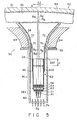
- Fig. 5 shows part of a color cathode ray tube apparatus according to a first embodiment of the present invention.
- Color cathode ray tube apparatus 50 comprises envelope 61 which includes panel section 52, funnel section 58 bonded to panel section 52, and neck section 60 continuous with funnel section 58.
- Panel section 52 has face plate 54 which is substantially rectangular in shape and a skirt (not shown) extending from the peripheral edge of plate 54.
- the inside of the color cathode ray tube is kept at a vacuum by Sections 52, 58 and 60.
- Electron gun assembly 62 is used for emitting three electron beams B R , B G , and B B and is housed inside neck section 60.
- Deflecting device 64 which includes horizontal and vertical deflecting coils, is mounted on the outer peripheral surfaces of funnel and neck sections 58 and 60.
- the horizontal and vertical deflecting coils serve to generate magnetic fields in order to deflect electron beams B R , B G , and B B horizontally and vertically, respectively.
- Multipolar magnet 65 for adjusting the tracks of the electron beams is mounted on neck section 60.
- Phosphor screen 66 is formed on the inner surface of face plate 54 of panel section 52. Inside the tube, a substantially rectangular shadow mask (not shown) is arranged opposite screen 66 so that a predetermined space is kept between the mask and face plate 54.
- the mask which is formed of a metal sheet, has a number of perforations.
- Internal conductor film 72 is applied to the inner wall surface of part of envelope 61 between funnel and neck sections 58 and 60.
- a plurality of stem pins 74 are attached to the end portion of neck section 60.
- Electron gun assembly 62 inside neck section 60 includes three cathodes K1 for generating electrons, planar first grid G1, planar second grid G2, and third, fourth, fifth, and sixth grids G3, G4, G5, and G6.
- Sixth grid G6 is provided with valve spacer 76 for supporting assembly 62.
- Electron gun assembly 62 is connected to stem pins 74 (connection is not shown in Fig. 5).
- Each cathode K1 has a heater (not shown) therein.
- First and second grids G1 and G2 are each provided with three small beam apertures corresponding to cathodes K1. This portion constitutes electron beam forming unit GE1.
- Third, fourth, and fifth grids G3, G4, and G5 are each provided with three relatively large beam apertures 78, as shown in Fig. 6.
- Fig. 6 shows beam apertures 78 of fourth grid G4, or of third or fifth grid G3 or G5, as viewed from the fourth-grid side.
- Each aperture 78 is substantially in the form of an ellipse whose diameter in the vertical direction (Y-direction) is shorter than its diameter in the horizontal direction (X-direction).
- Auxiliary electrode G5D for use as means for correcting the convergence and focusing of the three electron beams, is disposed inside that portion of fifth grid G5 on the sixth-grid side. As shown in Fig. 7, electrode G5D has three rectangular electron beam apertures 80. The auxiliary electrode is located at predetermined distance a from that end of fifth grid G5 on the sixth-grid side.
- Sixth grid G6 is a substantially cylindrical electrode which partially covers and surrounds fifth grid G5 in the form of a cylindrical electrode. A large-aperture cylindrical electron lens is practically formed between sixth grid G6 and the large beam apertures of fifth grid G5.
- Valve spacer 76 which is attached to the outer periphery of the distal end portion of sixth grid G6, is in contact with conductor film 72 applied to the inner surfaces of funnel and neck sections 58 and 60. In this arrangement, high voltage is supplied from an anode terminal attached to funnel section 58.
- All the electrodes of electron gun assembly 62 except sixth grid G6 are supplied with voltage from stem pins 74.
- First grid G1 is at an earth potential.
- Voltages of 500 V to 1 kV, 5 kV to 10 kV, 500 V to 10 kV, 5 kV to 10 kV, and 25 kV to 35 kV (high anode voltage) are applied to second, third, fourth, fifth, and sixth grids G2, G3, G4, G5, and G6, respectively.
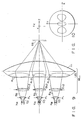
- Figs. 8 and 9 optically equivalently show a state of the electron beams.
- three electron beams B R , B G , and B B are generated from cathodes K1 in accordance with a modulation signal.
- Each of these electron beams is formed into crossover CO by means of first and second grids G1 and G2.
- each electron beam is slightly focused into an imaginary crossover by means of prefocus lens PL, which is formed of second and third grids G2 and G3.
- Electron beams B R , B G , and B B are diffused as they are rendered incident on third grid G3.
- the electron beams, incident on third grid G3, are focused by means of main electron lens unit ML1, which is formed of third to sixth grids G3 to G6. Outside beams B R and B B are also converged by lens unit ML1.
- electron beams B R , B G , and B B are landed on phosphor screen 66.
- Electron beams B R , B G , and B B are slightly focused by means of individual weak unipotential lenses EL2 (second electron lenses), which are formed of third, fourth, and fifth grids G3, G4, and G5. Since fourth grid G4 has substantially elliptic apertures, as mentioned before, lenses EL2 are formed as so-called astigmatic lenses whose focusing force is stronger in the vertical direction than in the horizontal direction. Accordingly, electron beams B R , B G , and B B are focused stronger in the vertical direction than in the horizontal direction. Thereafter, the electron beams are rendered incident on large-aperture electron lens LEL.
- EL2 second electron lenses
- Large-aperture electron lens LEL is formed of fifth and sixth grids G5 and G6. Since the application of high voltage from the side of sixth grid G6 is controlled by electrode G5D, however, distal end portion G5T (common aperture for the three beams) and the cylinder (common aperture for the three beams) of sixth grid G6 constitute one large electron lens LL. Within the region of this lens, moreover, three astigmatic lenses AL1, AL2, and AL3 are formed on the low-voltage side.
- the power of electron lens LL is first set so that the three electron beams are accurately converged on phosphor screen 66. Then, the respective powers of three astigmatic lenses AL1, AL2, and AL3 are set in order that the three beams are accurately focused on screen 66.
- outside apertures 80 of electrode G5D are made wider than the central aperture, as shown in Fig. 7, so that lenses AL1 and AL3 are less powerful than lens AL2.
- Position O of the center of each outside aperture of electrode G5D is situated outside central axis M of its corresponding outside apertures of grids G1, G2, G3, and G4, without being aligned therewith.
- the outside beams pass near the respective central axes of their corresponding astigmatic lenses AL1 and AL3, so that comae are produced. Since the outside beams are subjected to a coma produced by electron lens LL, however, the comae of the outside beams are canceled by the lenses. Thus, spots of the outside beams formed on the phosphor screen enjoy a satisfactory configuration.
- the core of the present invention lies in that the state of focus of the electron beams, focused in the vertical direction (Y-Z direction) by the large-aperture electron lens, is different from the state of focus in the horizontal direction (X-Z direction). This difference occurs because he focusing force of the astigmatic lenses in the vertical direction is weaker than the focusing force in the horizontal direction, since the apertures of electrode G5D are vertically elongated. In this case, the vertical diameter of each electron beam passing through the large-aperture electron lens is shorter than its horizontal diameter. Thus, in the region where the magnetic fields are generated by means of the deflecting device, the vertical beam diameter is shorter than the horizontal diameter. In this state, the electron beams are landed on the phosphor screen.
- the change of the vertical diameter of the electron beams affected by the deflecting device is larger than the change of the horizontal diameter thereof, the electron beams cannot be easily influenced by the deflecting magnetic fields generated by the deflecting device. In consequence, spots of the electron beams landed on the phosphor screen enjoy a satisfactory configuration, so that the color cathode ray tube can produce pictures of very high quality.
- fifth grid G5 has the three rectangular apertures.
- grid G5 may be formed with three substantially elliptic apertures, as shown in Fig. 10.
- a magnetic field correcting element for correcting the magnetic fields generated by the deflecting device may be attached to the distal end portion of sixth grid G6.
- Fig. 11 shows part of a color cathode ray tube apparatus according to a second embodiment of the present invention.
- Color cathode ray tube apparatus 100 comprises envelope 111 which includes panel section 102, funnel section 108 bonded to panel section 102, and neck section 110 continuous with funnel section 108.
- Panel section 102 has face plate 104 which is substantially rectangular in shape and a skirt (not shown) extending from the peripheral edge of plate 104.
- the inside of the color cathode ray tube is kept at a vacuum by sections 102, 108 and 110.
- Electron gun assembly 112 is used for emitting three electron beams B R , B G , and B B and is housed inside neck section 110.
- Deflecting device 114 which includes horizontal and vertical deflecting coils, is mounted on the outer peripheral surfaces of funnel and neck sections 108 and 110.
- the horizontal and vertical deflecting coils serve to generate magnetic fields in order to deflect electron beams B R , B G , and B B horizontally and vertically, respectively.
- Multipolar magnet 115 for adjusting the tracks of the electron beams is mounted on neck section 110.
- Phosphor screen 116 is formed on the inner surface of face plate 104 of panel section 102. Inside the tube, a substantially rectangular shadow mask (not shown) is arranged opposite screen 116 so that a predetermined space is kept between the mask and face plate 104.
- the mask which is formed of a metal sheet, has a number of perforations.
- Internal conductor film 122 is applied to the inner wall surface of part of envelope 111 between funnel and neck sections 108 and 110.
- a plurality of stem pins 124 are attached to the end portion of neck section 110.
- Electron gun-assembly 112 inside neck section 110 includes three cathodes K'1 for generating electrons, planar first grid G'1, planar second grid G'2, and third, fourth, fifth, and sixth grids G'3, G'4, G'5, and G'6.
- Sixth grid G'6 is provided with valve spacer 126 for supporting assembly 112.
- Electron gun assembly 112 is connected to stem pins 124 (connection is not shown in Fig. 11).
- Each cathode K'1 has a heater (not shown) therein.
- First and second grids G'1 and G'2 are each provided with three small beam apertures corresponding to cathodes K'1. This portion constitutes electron beam forming unit GE'1.
- Third, fourth, and fifth grids G'3, G'4, and G'5 are each provided with three relatively large beam apertures 128 different from those of the first embodiment, as shown in Fig. 12.
- Fig. 12 shows beam apertures 128 of fourth grid G'4, or of third or fifth grid G'3 or G'5, as viewed from the fourth-grid side.
- Each aperture 128 is substantially in the form of a circle whose diameter in the vertical direction (Y-direction) is equivalent to its diameter in the horizontal direction (X-direction).
- Auxiliary electrode G'5D shown in Figs. 13A and 13B for use as means for correcting the convergence and focusing of the three electron beams, is disposed inside that portion of fifth grid G'5 on the side nearest sixth-grid G'6. Also shown in Figs. 13A and 13B, electrode G'5D has three rectangular electron beam apertures 130. A pair of electric field control electrodes G'5H are arranged individually above and below apertures 130 of auxiliary electrode G'5D. Each electrode G'5H projects for length b . Auxiliary electrode G'5D is located at predetermined distance a from that end of fifth grid G'5 on the side nearest sixth-grid G'6.
- Sixth grid G'6 is a substantially cylindrical electrode which partially covers and surrounds fifth grid G'5 in the form of a cylindrical electrode.
- a large-aperture cylindrical electron lens is practically formed between sixth grid G'6 and the large beam apertures of fifth grid G'5.
- Valve spacer 126 which is attached to the outer periphery of the distal end portion of sixth grid G'6, is in contact with conductor film 122 applied to the inner surfaces of funnel and neck sections 108 and 110. In this arrangement, high voltage is supplied from an anode terminal attached to funnel section 108.
- All the electrodes of electron gun assembly 112 except sixth grid G'6 are supplied with voltage from stem pins 124.
- First grid G'1 is at an earth potential.
- Voltages of 500 V to 1 kV, 5 kV to 10 kV, 500 V to 10 kV, 5 kV to 10 kV, and 25 kV to 35 kV (high anode voltage) are applied to second, third, fourth, fifth, and sixth grids G'2, G'3, G'4, G'5, and G'6, respectively.
- Figs. 8 and 9 show a such state of the electron beams.
- Three electron beams B R , B G , and B B are generated from cathodes K'1 (Fig. 11) in accordance with a modulation signal.
- each of these electron beams is formed into crossover CO by means of first and second grids.
- each electron beam is slightly focused into an imaginary crossover by means of prefocus lens PL-, which is formed of second and third grids.
- Electron beams B R , B G , and BB are diffused as they are rendered incident on third grid G'3.
- the electron beams, incident on the third grid are focused by means of main electron lens unit ML1, which is formed of third to fifth grids.
- Electron beams BR, B G , and B B are rendered incident on large-aperture electron lens LEL.
- large-aperture electron lens LEL is formed of fifth and sixth grids G'5 and G'6. Since the application of high voltage from the side of sixth grid G'6 is controlled by electrode G'5D, however, distal end portion G'5T (common aperture for the three beams) and the cylinder (common aperture for the three beams) of sixth grid G'6 constitute one large electron lens LL . Within the region of this lens, moreover, three astigmatic lenses AL 1, AL 2, and AL 3 are formed on the low-voltage side.
- the power of electron lens LL is first set so that the three electron beams are accurately converged on phosphor screen 116. Then, the respective powers of three astigmatic lenses AL 1, AL 2, and AL 3 are set in order that the three beams are accurately focused on screen 116. In this case, outside apertures 130 of electrode G'5D are made wider than the central aperture, as shown in Fig. 13A, so that lenses AL 1 and AL 3 are less powerful than lens AL 2. Thus, focus differences between two outside beams and a central beam, produced by electron lens LL , are corrected.
- a pair of electric field control electrodes G'5H are arranged individually above and below the three electron beam apertures of auxiliary electrode G'5D inside fifth grid G5. Electrodes G'5H serve to control focusing electric fields on the low-voltage side of large-aperture electron lens LEL, which is formed of fifth and sixth grids G'5 and G'6. Thus, the three electron beams are strongly focused in the vertical direction. Position O' of the center of each outside aperture of electrode G'5D is situated outside central axis M' of its corresponding outside apertures of grids G'1, G'2, G'3, and G'4, without being aligned therewith.
- the focusing electric fields on the low-voltage side of lens LEL which is formed of fifth and sixth grids G'5 and G'6, are controlled by means of electrodes G'5H. Accordingly, the three electron beams are strongly focused in the vertical direction. Since the outside electron beams are strongly focused by the large-aperture electron lens formed of fifth and sixth grids G'5 and G'6, the beams are properly focused in the vertical direction, as well as in the horizontal direction.
- electric field control electrodes G'5H are mounted on auxiliary electrode G'5D inside fifth grid G'5, the vertically focusing capability of the electron beams is higher than in the first embodiment.
- the vertical resolution of a picture projected on the phosphor screen is improved.
- Fig. 14 shows part of a color cathode ray tube apparatus according to a third embodiment of the present invention.
- Color cathode ray tube apparatus 150 comprises envelope 161 which includes panel section 152, funnel section 158 bonded to panel section 152, and neck section 160 continuous with funnel section 158.
- Panel section 152 has substantially rectangular face plate 154 and a skirt (not shown) extending from the peripheral edge of plate 154.
- the inside of the color cathode ray tube is kept at a vacuum by sections 152, 158 and 160.
- Electron gun assembly 162 is used for emitting three electron beams B R , B G , and B B and is housed inside neck section 160.
- Deflecting device 164 which includes horizontal and vertical deflecting coils, is mounted on the outer peripheral surfaces of funnel and neck sections 158 and 160.
- the horizontal and vertical deflecting coils serve to generate magnetic fields in order to deflect electron beams B R ,B G , and B B horizontally and vertically, respectively.
- Multipolar magnet 165 for adjusting the tracks of the electron beams is mounted on neck section 160.
- Phosphor screen 166 is formed on the inner surface of face plate 154 of panel section 152. Inside the tube, a substantially rectangular shadow mask (not shown) is arranged opposite screen 166 so that a predetermined space is kept between the mask and face plate 154.
- the mask which is formed of a metal sheet, has a number of perforations.
- Internal conductor film 172 is applied to the inner wall surface of part of envelope 161 between funnel and neck sections 158 and 160.
- a plurality of stem pins 174 are attached to the end portion of neck section 160.
- Electron gun assembly 162 inside neck section 160 includes three cathodes K 3 1 for generating electrons, planar first grid G 3 1, planar second grid G 3 2, and third, fourth, fifth, sixth, seventh, and eighth grids G 3 3, G 3 4, G 3 5, G 3 6, G 3 7, and G 3 8.
- Eighth grid G 3 8 is provided with valve spacer 176 for supporting assembly 162.
- Electron gun assembly 162 is connected to stem pins 174 (connection is not shown in Fig. 16). Further, correction circuit 177 is connected to sixth grid G 3 6 via stem pins 174. Circuit 177 supplies a voltage which changes in a parabolic configuration in synchronism with a current supplied to the deflecting device.
- Each cathode K 3 1 has a heater (not shown) therein.
- First and second grids G 3 1 and G 3 2 are each provided with three small beam apertures corresponding to cathodes K 3 1. This portion constitutes electron beam forming unit GE 3 1.
- Third, fourth, and fifth grids G 3 3, G 3 4, and G 3 5 are each provided with three relatively large beam apertures 128.
- apertures 128 of third grid G 3 3, fourth grid G 3 4, or fifth grid G 3 5 as viewed from the fourth-grid side are shown in Fig. 12.
- Each aperture 128 is substantially in the form of a circle whose diameter in the vertical direction (Y-direction) is equal to its diameter in the horizontal direction (X-direction).
- Unipotential lenses which are formed of third, fourth, and fifth grids G 3 3, G 3 4, and G 3 5, have equal focusing forces in the vertical and horizontal directions.
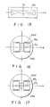
- Fig. 15 shows beam aperture 178 of sixth grid G 3 6, or of fifth or seventh grid G 3 5 or G 3 7, as viewed from the sixth-grid side.
- Aperture 178 is a common aperture for the three electron beams, and its horizontal diameter is about five times as long as its vertical diameter or more.
- Unipotential lenses, which are formed of fifth, sixth, and seventh grids G 3 5, G 3 6, and G 3 7, are so-called parallel plate lenses which focus the electron beams only in the vertical direction, without substantially focusing the beams in the horizontal direction.
- Electrode G 3 7D which is shown in Fig. 16, includes two pairs of electric field control electrodes G 3 7H which project for length b , from the regions above and below the outside beam apertures toward eighth grid G 3 8.
- All the electrodes of electron gun assembly 162 except eighth grid G 3 8 are supplied with voltage from stem pins 174.
- First grid G 3 1 is at an earth potential.
- Voltages of 500 V to 1 kV, 5 kV to 10 kV, 500 V to 3 kV, 5 kV to 10 kV, 3 kV to 9-kV, 5 kV to 10 kV, and 25 kV to 35 kV (high anode voltage) are applied to second, third, fourth, fifth, sixth, seventh, and eighth grids G 3 2, G 3 3, G 3 4, G 3 5, G 3 6, G 3 7, and G 3 8, respectively.
- three electron beams B R , B G , and B B are generated from cathodes K 3 1 in accordance with a modulation signal.
- the electron lens of the third embodiment is similar to that of the first embodiment shown in Figs. 8 and 9, each of these electron beams is formed into crossover CO by means of first and second grids. Then, each electron beam is slightly focused into an imaginary crossover by means of prefocus lens PL , which is formed of second and third grids. As shown in Fig. 16, electron beams B R , B G , and B B are diffused as they are rendered incident on third grid G 3 3.
- the electron beams, incident on third grid G 3 3, are slightly focused by means of the individual weak unipotential lenses, which are formed of third, fourth, and fifth grids G 3 3, G 3 4, and G 3 5.
- electron beams B R , B G , and B B incident on the parallel plate lenses formed of fifth, sixth, and seventh grids G 3 5, G 3 6, and G 3 7, are focused only in the vertical direction.
- the electron beams are focused more strongly in the vertical direction than in the horizontal direction.
- the electron beams are rendered incident on the large-aperture electron lens, which is formed of seventh and eighth grids G 3 7 and G 3 8.
- the electron beams are properly converged and focused by the large-aperture electron lens.
- electron beams B R , B G , and B B are landed with an appropriate beam spot configuration on the phosphor screen.
- length b of two pairs of electric field control electrodes G 3 7H of auxiliary electrode G 3 7D is shorter than that of the electric control electrodes of the second embodiment. Therefore, the difference between the degrees of focus of the electron beams in the vertical and horizontal directions is smaller in this embodiment than in the first embodiment.
- electron beams B R , B G , and B B can be properly landed on the phosphor screen.
- the position of the center of each outside aperture of electrode G 3 7D is situated outside the central axis of its corresponding outside apertures of grids G 3 1, G 3 2, G 3 3, and G 3 4, without being aligned therewith.
- the outside electron beams pass near the respective central axes of their corresponding astigmatic lenses, as in the first embodiment, so that comae are produced. Since the outside beams are subjected to a coma produced by the electron lens formed between seventh and eighth grids G 3 7 and G 3 8, however, the comae of the outside beams are canceled by the lenses. Thus, spots of the outside beams formed on the phosphor screen enjoy a satisfactory configuration. As in the case of the second embodiment, the electron beams are strongly focused in the vertical direction, so that the vertical focusing capability of the electron beams is improved. Thus, the vertical diameter of the beam spots can be reduced.
- the vertical diameter of each electron beam is shorter than its horizontal diameter in the region where the electron beams are deflected,-so that the beams cannot easily be subjected to a deflective aberration. In consequence, the shape of the beam spots in the peripheral region of the screen is improved.
- the electric field control electrodes are arranged individually above and below the three electron beam apertures of the auxiliary electrode.
- the electric field control electrodes are arranged above and below only the outside electron beam apertures of the auxiliary electrode. In this arrangement, the difference in the degrees of focus between the outside electron beams and the central electron beam can be reduced. Thus, the outside and central beams can enjoy higher focusing capability than in the second embodiment.
- correction circuit 177 which is connected to sixth grid G36, changes the power of the electron lens in synchronism with the change of the state of deflection.
- deflection distortion of the electron beams is corrected, so that the beam spot shape is appropriate.
- the configuration of the auxiliary electrode is not limited to the one shown in Fig. 16, and the auxiliary electrode may alternatively be shaped as shown in Fig. 17.
- the parallel plate lenses may be bipotential lenses, instead of being unipotential lenses.
- Each cathode K 4 1 has a heater (not shown) therein.
- First and second grids G 4 1 and G 4 2 are each provided with three small beam apertures corresponding to cathodes K 4 1. This portion constitutes electron beam forming unit GE 4 1.
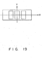
- the configuration of electron beam apertures of third grid G 4 3 or fifth grid G 4 5, as viewed from the fourth-grid side, is shown in Fig. 19. These apertures are vertically elongated openings, three in each set.
- An electron beam aperture of fourth grid G 4 4, which is shown in Fig. 15, is a single slit long from side to side, as in the case of the third embodiment.
- unipotential lenses which are formed of third, fourth, and fifth grids G 4 3, G 4 4, and G 4 5, are so-called four-pole lenses which focus the electron beams in the vertical direction, and diffuse them in the horizontal direction.
- Fifth and sixth grids G 4 5 and G 4 6 are formed in the same manner as their counterparts in the first embodiment.
- three electron beams B R , B G , and B B are generated from cathodes K 4 1 in accordance with a modulation signal.
- the electron lens of the fourth embodiment is similar to that of the first embodiment shown in Figs. 8 and 9.
- Each of these electron beams is formed into crossover CO by means of first and second grids.
- each electron beam is slightly focused into imaginary crossover by means of prefocus lens PL , which is formed of second and third grids.
- prefocus lens PL As shown in Fig. 20 electron beams B R , B G , and B B B are diffused as they are rendered incident on third grid G 4 3.
- the electron beams, incident on third grid G 4 3, are separately focused in the vertical direction and diffused in the horizontal direction, by the individual four-pole lenses formed of third, fourth, and fifth grids G 4 3, G 4 4, and G 4 5. Thereafter, electron beams B R , B G , and B B are rendered incident on a large-aperture electron lens, which is formed of fifth and sixth grids grids G 4 5 and G 4 6. Thereupon, as in the case of the first embodiment, the electron beams are converged and focused on the phosphor screen by the large-aperture electron lens.
- correction circuit 227 which is connected to sixth grid G 4 6, changes the power of the electron lens in synchronism with the change of the state of deflection.
- deflection distortion of the electron beams is corrected, so that the beam spot shape is appropriate.
- the large-aperture electron lens enables the three electron beams to be converged and focused most suitably on the phosphor screen.
- the beam spots can be made very small, so that the performance of the color cathode ray tube apparatus can be improved.
Landscapes
- Video Image Reproduction Devices For Color Tv Systems (AREA)
- Cathode-Ray Tubes And Fluorescent Screens For Display (AREA)
Claims (7)
- Farbkathodenstrahlröhrenvorrichtung, umfassend:einen Vakuumkolben (111, 161) mit einer Frontplattensektion (102, 152), einer Trichtersektion (108, 158) und einer Halssektion (110, 160), wobei die Frontplattensektion (102, 152) eine Achse und einen Schirmträger (104, 154), dessen Form, in Vorderansicht, im wesentlichen rechteckig ist und der eine Innenfläche aufweist, sowie ein von der Umfangskante des Schirmträgers (104, 154) abgehendes Randteil aufweist, die Halssektion (110, 160) im wesentlichen zylindrisch geformt ist und die Trichtersektion (108, 158) (kontinuierlich) in die Halssektion (110, 160) übergeht,einen auf der Innenfläche des Schirmträgers (104; 154) geformten Leuchtstoffschirm (116, 166),eine innerhalb der Frontplattensektion (102, 152) dem Leuchtstoffschirm (116, 166) am Schirmträger (104, 154) zugewandt angeordnete Schattenmaske,eine in der Halssektion (110, 160) untergebrachte Inline-Elektronenkanonenanordnung (112, 162) mit einer Elektronenstrahlformungseinheit zum Erzeugen, Steuern und Beschleunigen von drei Elektronenstrahlen, umfassend einen Mittenelektronenstrahl und zwei Seitenelektronenstrahlen, sowie einer Hauptlinseneinheit (ML2) zum Konvergieren und Fokussieren der drei Elektronenstrahlen undeine Ablenkvorrichtung (114, 164) zum vertikalen und horizontalen Ablenken der von der Elektronenkanonenanordnung emittierten Elektronenstrahlen,dadurch gekennzeichnet, daß
die Hauptelektronenlinseneinheit (ML2) eine eine große Apertur besitzende Elektronenlinse, die für die drei Elektronenstrahlen gemeinsam vorgesehen ist, und einzelne, jeweils getrennt für die drei Elektronenstrahlen vorgesehene Elektronenlinsen (G'3, G'4, G'5), so daß die Seitenelektronenstrahlen eine(r) Aberration in einer solchen Richtung erzeugen bzw. unterliegen, daß die Komponente einer durch die eine große Apertur besitzende bzw. Großapertur-Elektronenlinse hervorgerufenen Aberration im Bereich der Großapertur-Elektronenlinse aufgehoben wird, ein im Bereich der Großapertur-Elektronenlinse angeordnetes Fokussierkraft-Korrigiermittel (G'5D), welches die Vertikalfokussierkraft an mindestens einem der Elektronenstrahlen zu verstärken vermag, und ein Mittel (LEL') zum einzelnen bzw. jeweiligen Formen von Elektronenstrahlen aufweist, die in der Horizontalrichtung vergleichsweise stärker streuen als in der Vertikalrichtung, so daß sich die jeweiligen Mittelachsen der auf die Großapertur-Elektronenlinse einfallenden Seitenelektronenstrahlen nicht verändern, aber die Größe und/oder Form der Seitenelektronenstrahlen sich konstant oder ständig ändert, wobei das Strahlformungsmittel in bezug auf die Großapertur-Elektronenlinse an der Seite der Elektronenstrahlformungseinheit vorgesehen ist. - Farbkathodenstrahlröhrenvorrichtung nach Anspruch 1, dadurch gekennzeichnet, daß
die Hauptelektronenlinseneinheit (ML2) die Großapertur-Elektronenlinse mit mindestens einer zylindrischen Elektrode, durch welche die drei Elektronenstrahlen gemeinsam geführt werden, einer die erste zylindrische Elektrode überlappenden zweiten zylindrischen Elektrode und einer Plattenelektrode umfaßt, die senkrecht zu den Strahlachsen innerhalb der ersten zylindrischen Elektrode angeordnet ist und drei Strahlaperturen, durch welche die drei Elektronenstrahlen (jeweils) einzeln hindurchlaufen, aufweist. - Farbkathodenstrahlröhrenvorrichtung nach Anspruch 1, dadurch gekennzeichnet, daß
die Hauptelektronenlinseneinheit (ML2) eine Großapertur-Elektronenlinse mit mindestens einer ersten zylindrischen Elektrode, durch welche die drei Elektronenstrahlen gemeinsam geführt werden, einer die erste zylindrische Elektrode überlappenden zweiten zylindrischen Elektrode, einer senkrecht zu den Strahlachsen innerhalb der ersten zylindrischen Elektrode angeordneten Plattenelektrode mit drei Strahlaperturen, durch welche die drei Elektronenstrahlen (jeweils) einzeln hindurchlaufen, und zwei parallel zur Laufrichtung der Elektronenstrahlen vorstehenden Elektroden zum Steuern eines elektrischen Felds umfaßt, welche (Elektroden) horizontal an jeder Seite mindestens einer zentralen Elektronenstrahlapertur oder von außenseitigen Elektronenstrahlaperturen unter den drei Strahlaperturen der Hilfselektrode angeordnet sind. - Farbkathodenstrahlröhrenvorrichtung nach Anspruch 2 oder 3, dadurch gekennzeichnet, daß von den drei Strahlaperturen der Plattenelektrode die Aperturen für die Seitenelektronenstrahlen größer sind als die für den Mittenelektronenstrahl.
- Farbkathodenstrahlröhrenvorrichtung nach einem der Ansprüche 2 oder 4, dadurch gekennzeichnet, daß das Mittel zum Formen der einzelnen Elektronenstrahlen, die in der Horizontalrichtung vergleichsweise stärker streuen als in der Vertikalrichtung, eine eine große Apertur besitzende bzw. Großapertur-Elektronenlinse (LEL') ist, bei welcher die Apertur in einer ersten Ebene (plate) (x, z) parallel zur Röhrenachse größer ist als in einer zweiten, parallel zur Röhrenachse und senkrecht zur ersten Ebene liegenden Ebene (y, z), so daß eine asymmetrische Linse gebildet ist.
- Farbkathodenstrahlröhrenvorrichtung nach einem der Ansprüche 2 bis 4, dadurch gekennzeichnet, daß das Mittel zum Formen der einzelnen Elektronenstrahlen, die in der Horizontalrichtung vergleichsweise stärker streuen als in der Vertikalrichtung, aus Quadrupollinsen besteht.
- Farbkathodenstrahlröhrenvorrichtung nach einem der Ansprüche 2 bis 6, dadurch gekennzeichnet, daß die drei auf die Großapertur-Elektronenlinse (LEL') einfallenden und im wesentlichen parallele Mittelachsen aufweisenden Elektronenstrahlen so angeordnet sind, daß die Elektronenstrahlachsen in einer Ebene liegen, wobei die Kathodenachsen und Aperturen um die in der einen Ebene parallel liegenden Strahlachsen zentriert sind.
Applications Claiming Priority (4)
| Application Number | Priority Date | Filing Date | Title |
|---|---|---|---|
| JP240809/88 | 1988-09-28 | ||
| JP24080988 | 1988-09-28 | ||
| JP25939288 | 1988-10-17 | ||
| JP259392/88 | 1988-10-17 |
Publications (3)
| Publication Number | Publication Date |
|---|---|
| EP0361455A2 EP0361455A2 (de) | 1990-04-04 |
| EP0361455A3 EP0361455A3 (de) | 1992-12-30 |
| EP0361455B1 true EP0361455B1 (de) | 1997-08-27 |
Family
ID=26534937
Family Applications (1)
| Application Number | Title | Priority Date | Filing Date |
|---|---|---|---|
| EP89117890A Expired - Lifetime EP0361455B1 (de) | 1988-09-28 | 1989-09-27 | Vorrichtung für eine Farbkathodenstrahlröhre |
Country Status (5)
| Country | Link |
|---|---|
| US (1) | US5091673A (de) |
| EP (1) | EP0361455B1 (de) |
| KR (1) | KR920007182B1 (de) |
| CN (1) | CN1040925C (de) |
| DE (1) | DE68928273T2 (de) |
Families Citing this family (7)
| Publication number | Priority date | Publication date | Assignee | Title |
|---|---|---|---|---|
| US5204585A (en) * | 1992-04-27 | 1993-04-20 | Chen Hsing Yao | Electron beam deflection lens for color CRT |
| JPH0729512A (ja) * | 1993-05-14 | 1995-01-31 | Toshiba Corp | カラー受像管 |
| US5412277A (en) * | 1993-08-25 | 1995-05-02 | Chunghwa Picture Tubes, Ltd. | Dynamic off-axis defocusing correction for deflection lens CRT |
| KR950012549A (ko) * | 1993-10-22 | 1995-05-16 | 에스. 씨. 첸 | 칼라 음극선관전자총을 위한 연장중앙 원형 개구를 가진 오목한 체인-링크 주렌즈 설계 |
| US5763993A (en) * | 1994-04-01 | 1998-06-09 | Samsung Display Devices Co., Ltd. | Focusing electrode structure for a color cathode ray tube |
| US5442263A (en) * | 1994-08-23 | 1995-08-15 | David Sarnoff Research Center, Inc. | Dynamic electrostatic and magnetic focusing apparatus for a cathode ray tube |
| KR100321287B1 (ko) * | 1999-07-24 | 2002-03-18 | 윤종용 | 프로젝션 텔레비젼 수신기내 광학시스템 |
Family Cites Families (11)
| Publication number | Priority date | Publication date | Assignee | Title |
|---|---|---|---|---|
| GB1195598A (en) * | 1967-01-14 | 1970-06-17 | Sony Corp | Cathode Ray Tube |
| US3875446A (en) * | 1969-06-02 | 1975-04-01 | Sony Corp | Acute angle source of plural beams for color cathode ray tube |
| BE793992A (fr) * | 1972-01-14 | 1973-05-02 | Rca Corp | Tube a rayons cathodiques |
| US4086513A (en) * | 1975-03-03 | 1978-04-25 | Rca Corporation | Plural gun cathode ray tube having parallel plates adjacent grid apertures |
| JPS5369A (en) * | 1976-06-23 | 1978-01-05 | Matsushita Electronics Corp | Double-beam electronic gun |
| US4406970A (en) * | 1981-07-10 | 1983-09-27 | Rca Corporation | Color picture tube having an expanded focus lens type inline electron gun with an improved stigmator |
| CA1196677A (en) * | 1982-02-26 | 1985-11-12 | Sony Corporation | Electron gun |
| US4766344A (en) * | 1983-04-21 | 1988-08-23 | North American Philips Consumer Electronics Corp. | In-line electron gun structure for color cathode ray tube having oblong apertures |
| US4528476A (en) * | 1983-10-24 | 1985-07-09 | Rca Corporation | Cathode-ray tube having electron gun with three focus lenses |
| JP2735176B2 (ja) * | 1986-03-19 | 1998-04-02 | 株式会社東芝 | カラー受像管 |
| DE3743895A1 (de) * | 1987-12-23 | 1989-07-13 | Herm Friedr Kuenne Fa | Abnehmbares ueberbrueckungsprofil fuer fussbodenfugen |
-
1989
- 1989-09-27 EP EP89117890A patent/EP0361455B1/de not_active Expired - Lifetime
- 1989-09-27 US US07/413,547 patent/US5091673A/en not_active Expired - Lifetime
- 1989-09-27 DE DE68928273T patent/DE68928273T2/de not_active Expired - Fee Related
- 1989-09-28 KR KR8913927A patent/KR920007182B1/ko not_active Expired
- 1989-09-28 CN CN89107668A patent/CN1040925C/zh not_active Expired - Fee Related
Also Published As
| Publication number | Publication date |
|---|---|
| CN1040925C (zh) | 1998-11-25 |
| KR910007057A (ko) | 1991-04-30 |
| EP0361455A3 (de) | 1992-12-30 |
| EP0361455A2 (de) | 1990-04-04 |
| CN1041478A (zh) | 1990-04-18 |
| KR920007182B1 (en) | 1992-08-27 |
| DE68928273T2 (de) | 1998-01-29 |
| US5091673A (en) | 1992-02-25 |
| DE68928273D1 (de) | 1997-10-02 |
Similar Documents
| Publication | Publication Date | Title |
|---|---|---|
| US4234814A (en) | Electron gun with astigmatic flare-reducing beam forming region | |
| EP0424888B1 (de) | Farbbildkathodenstrahlröhre | |
| EP0986088B1 (de) | Farbkathodenstrahlröhre mit niedrigen dynamischen Fokussierspannung | |
| US4935663A (en) | Electron gun assembly for color cathode ray tube apparatus | |
| US5066887A (en) | Color picture tube having an inline electron gun with an astigmatic prefocusing lens | |
| US5162695A (en) | Electron gun assembly for a color cathode ray tube | |
| US5034653A (en) | Electron gun having unipotential focusing lenses for color picture tube | |
| EP0658914B1 (de) | Farbkathodenstrahlröhrevorrichtung | |
| US5262702A (en) | Color cathode-ray tube apparatus | |
| EP0361455B1 (de) | Vorrichtung für eine Farbkathodenstrahlröhre | |
| EP0452789B1 (de) | Farbbildröhre mit "inline" Elektronenkanone mit Fokusjustierung | |
| US6614156B2 (en) | Cathode-ray tube apparatus | |
| US5864203A (en) | Dynamic focusing electron gun | |
| US5177399A (en) | Color cathode ray tube apparatus | |
| EP0388901B1 (de) | Farbkathodenstrahlröhre | |
| JPH08315751A (ja) | 陰極線管の偏向収差補正方法および陰極線管並びに画像表示装置 | |
| EP0238019A2 (de) | Elektronenstrahlerzeuger | |
| EP0348912B1 (de) | Farbbildröhre | |
| KR970006037B1 (ko) | 개선된 전자총을 갖는 음극선관 | |
| JP3672390B2 (ja) | カラー陰極線管用電子銃 | |
| KR910009635B1 (ko) | 다이나믹 포커스 전자총 | |
| JP2645071B2 (ja) | カラー受像管装置 | |
| JP3004658B2 (ja) | カラー受像管装置 | |
| JP2804052B2 (ja) | カラー受像管装置 | |
| JP2692877B2 (ja) | カラー受像管装置 |
Legal Events
| Date | Code | Title | Description |
|---|---|---|---|
| PUAI | Public reference made under article 153(3) epc to a published international application that has entered the european phase |
Free format text: ORIGINAL CODE: 0009012 |
|
| 17P | Request for examination filed |
Effective date: 19891024 |
|
| AK | Designated contracting states |
Kind code of ref document: A2 Designated state(s): DE FR GB |
|
| PUAL | Search report despatched |
Free format text: ORIGINAL CODE: 0009013 |
|
| AK | Designated contracting states |
Kind code of ref document: A3 Designated state(s): DE FR GB |
|
| RHK1 | Main classification (correction) |
Ipc: H01L 29/50 |
|
| 17Q | First examination report despatched |
Effective date: 19941108 |
|
| GRAG | Despatch of communication of intention to grant |
Free format text: ORIGINAL CODE: EPIDOS AGRA |
|
| GRAH | Despatch of communication of intention to grant a patent |
Free format text: ORIGINAL CODE: EPIDOS IGRA |
|
| GRAH | Despatch of communication of intention to grant a patent |
Free format text: ORIGINAL CODE: EPIDOS IGRA |
|
| GRAA | (expected) grant |
Free format text: ORIGINAL CODE: 0009210 |
|
| AK | Designated contracting states |
Kind code of ref document: B1 Designated state(s): DE FR GB |
|
| REF | Corresponds to: |
Ref document number: 68928273 Country of ref document: DE Date of ref document: 19971002 |
|
| ET | Fr: translation filed | ||
| PLBE | No opposition filed within time limit |
Free format text: ORIGINAL CODE: 0009261 |
|
| STAA | Information on the status of an ep patent application or granted ep patent |
Free format text: STATUS: NO OPPOSITION FILED WITHIN TIME LIMIT |
|
| 26N | No opposition filed | ||
| REG | Reference to a national code |
Ref country code: GB Ref legal event code: 746 Effective date: 19980915 |
|
| REG | Reference to a national code |
Ref country code: FR Ref legal event code: D6 |
|
| REG | Reference to a national code |
Ref country code: GB Ref legal event code: IF02 |
|
| PGFP | Annual fee paid to national office [announced via postgrant information from national office to epo] |
Ref country code: FR Payment date: 20060908 Year of fee payment: 18 |
|
| PGFP | Annual fee paid to national office [announced via postgrant information from national office to epo] |
Ref country code: DE Payment date: 20060922 Year of fee payment: 18 |
|
| PGFP | Annual fee paid to national office [announced via postgrant information from national office to epo] |
Ref country code: GB Payment date: 20060927 Year of fee payment: 18 |
|
| GBPC | Gb: european patent ceased through non-payment of renewal fee |
Effective date: 20070927 |
|
| PG25 | Lapsed in a contracting state [announced via postgrant information from national office to epo] |
Ref country code: DE Free format text: LAPSE BECAUSE OF NON-PAYMENT OF DUE FEES Effective date: 20080401 |
|
| REG | Reference to a national code |
Ref country code: FR Ref legal event code: ST Effective date: 20080531 |
|
| PG25 | Lapsed in a contracting state [announced via postgrant information from national office to epo] |
Ref country code: FR Free format text: LAPSE BECAUSE OF NON-PAYMENT OF DUE FEES Effective date: 20071001 |
|
| PG25 | Lapsed in a contracting state [announced via postgrant information from national office to epo] |
Ref country code: GB Free format text: LAPSE BECAUSE OF NON-PAYMENT OF DUE FEES Effective date: 20070927 |