EP0361472B1 - Dispositif à cristal liquide ferro-électrique - Google Patents
Dispositif à cristal liquide ferro-électrique Download PDFInfo
- Publication number
- EP0361472B1 EP0361472B1 EP89117950A EP89117950A EP0361472B1 EP 0361472 B1 EP0361472 B1 EP 0361472B1 EP 89117950 A EP89117950 A EP 89117950A EP 89117950 A EP89117950 A EP 89117950A EP 0361472 B1 EP0361472 B1 EP 0361472B1
- Authority
- EP
- European Patent Office
- Prior art keywords
- angle
- liquid crystal
- ferroelectric liquid
- polarizer
- crystal panel
- Prior art date
- Legal status (The legal status is an assumption and is not a legal conclusion. Google has not performed a legal analysis and makes no representation as to the accuracy of the status listed.)
- Expired - Lifetime
Links
- 239000005262 ferroelectric liquid crystals (FLCs) Substances 0.000 title claims abstract description 82
- 230000005540 biological transmission Effects 0.000 claims abstract description 77
- 239000000758 substrate Substances 0.000 claims abstract description 19
- 210000002858 crystal cell Anatomy 0.000 abstract description 7
- 239000004973 liquid crystal related substance Substances 0.000 description 37
- 239000000463 material Substances 0.000 description 4
- 239000000203 mixture Substances 0.000 description 4
- 230000010287 polarization Effects 0.000 description 4
- 230000002269 spontaneous effect Effects 0.000 description 4
- 239000004990 Smectic liquid crystal Substances 0.000 description 3
- 230000007423 decrease Effects 0.000 description 3
- 230000003247 decreasing effect Effects 0.000 description 2
- 239000011324 bead Substances 0.000 description 1
- 230000015572 biosynthetic process Effects 0.000 description 1
- 239000011248 coating agent Substances 0.000 description 1
- 238000000576 coating method Methods 0.000 description 1
- 239000007788 liquid Substances 0.000 description 1
- 238000000034 method Methods 0.000 description 1
- 239000002052 molecular layer Substances 0.000 description 1
- 125000006850 spacer group Chemical group 0.000 description 1
Images


Classifications
-
- G—PHYSICS
- G02—OPTICS
- G02F—OPTICAL DEVICES OR ARRANGEMENTS FOR THE CONTROL OF LIGHT BY MODIFICATION OF THE OPTICAL PROPERTIES OF THE MEDIA OF THE ELEMENTS INVOLVED THEREIN; NON-LINEAR OPTICS; FREQUENCY-CHANGING OF LIGHT; OPTICAL LOGIC ELEMENTS; OPTICAL ANALOGUE/DIGITAL CONVERTERS
- G02F1/00—Devices or arrangements for the control of the intensity, colour, phase, polarisation or direction of light arriving from an independent light source, e.g. switching, gating or modulating; Non-linear optics
- G02F1/01—Devices or arrangements for the control of the intensity, colour, phase, polarisation or direction of light arriving from an independent light source, e.g. switching, gating or modulating; Non-linear optics for the control of the intensity, phase, polarisation or colour
- G02F1/13—Devices or arrangements for the control of the intensity, colour, phase, polarisation or direction of light arriving from an independent light source, e.g. switching, gating or modulating; Non-linear optics for the control of the intensity, phase, polarisation or colour based on liquid crystals, e.g. single liquid crystal display cells
- G02F1/137—Devices or arrangements for the control of the intensity, colour, phase, polarisation or direction of light arriving from an independent light source, e.g. switching, gating or modulating; Non-linear optics for the control of the intensity, phase, polarisation or colour based on liquid crystals, e.g. single liquid crystal display cells characterised by the electro-optical or magneto-optical effect, e.g. field-induced phase transition, orientation effect, guest-host interaction or dynamic scattering
- G02F1/139—Devices or arrangements for the control of the intensity, colour, phase, polarisation or direction of light arriving from an independent light source, e.g. switching, gating or modulating; Non-linear optics for the control of the intensity, phase, polarisation or colour based on liquid crystals, e.g. single liquid crystal display cells characterised by the electro-optical or magneto-optical effect, e.g. field-induced phase transition, orientation effect, guest-host interaction or dynamic scattering based on orientation effects in which the liquid crystal remains transparent
- G02F1/141—Devices or arrangements for the control of the intensity, colour, phase, polarisation or direction of light arriving from an independent light source, e.g. switching, gating or modulating; Non-linear optics for the control of the intensity, phase, polarisation or colour based on liquid crystals, e.g. single liquid crystal display cells characterised by the electro-optical or magneto-optical effect, e.g. field-induced phase transition, orientation effect, guest-host interaction or dynamic scattering based on orientation effects in which the liquid crystal remains transparent using ferroelectric liquid crystals
-
- G—PHYSICS
- G09—EDUCATION; CRYPTOGRAPHY; DISPLAY; ADVERTISING; SEALS
- G09F—DISPLAYING; ADVERTISING; SIGNS; LABELS OR NAME-PLATES; SEALS
- G09F9/00—Indicating arrangements for variable information in which the information is built-up on a support by selection or combination of individual elements
- G09F9/30—Indicating arrangements for variable information in which the information is built-up on a support by selection or combination of individual elements in which the desired character or characters are formed by combining individual elements
- G09F9/35—Indicating arrangements for variable information in which the information is built-up on a support by selection or combination of individual elements in which the desired character or characters are formed by combining individual elements being liquid crystals
-
- G—PHYSICS
- G02—OPTICS
- G02F—OPTICAL DEVICES OR ARRANGEMENTS FOR THE CONTROL OF LIGHT BY MODIFICATION OF THE OPTICAL PROPERTIES OF THE MEDIA OF THE ELEMENTS INVOLVED THEREIN; NON-LINEAR OPTICS; FREQUENCY-CHANGING OF LIGHT; OPTICAL LOGIC ELEMENTS; OPTICAL ANALOGUE/DIGITAL CONVERTERS
- G02F1/00—Devices or arrangements for the control of the intensity, colour, phase, polarisation or direction of light arriving from an independent light source, e.g. switching, gating or modulating; Non-linear optics
- G02F1/01—Devices or arrangements for the control of the intensity, colour, phase, polarisation or direction of light arriving from an independent light source, e.g. switching, gating or modulating; Non-linear optics for the control of the intensity, phase, polarisation or colour
- G02F1/13—Devices or arrangements for the control of the intensity, colour, phase, polarisation or direction of light arriving from an independent light source, e.g. switching, gating or modulating; Non-linear optics for the control of the intensity, phase, polarisation or colour based on liquid crystals, e.g. single liquid crystal display cells
- G02F1/133—Constructional arrangements; Operation of liquid crystal cells; Circuit arrangements
- G02F1/1333—Constructional arrangements; Manufacturing methods
- G02F1/1335—Structural association of cells with optical devices, e.g. polarisers or reflectors
- G02F1/133528—Polarisers
- G02F1/133531—Polarisers characterised by the arrangement of polariser or analyser axes
Definitions
- the present invention relates to a liquid crystal apparatus using a ferroelectric liquid crystal, particularly a ferroelectric liquid crystal display apparatus with suppressed color irregularity.
- Clark and Lagerwall have disclosed a surface-stabilized bistable ferroelectric liquid crystal in Applied Physics Letters, Vol. 36, No. 11 (June 1, 1980), p.p. 899- 901, and U.S. Patents Nos. 4,367,924 and 4,563,059.
- the bistable ferroelectric liquid crystal has been realized by disposing a chiral smectic liquid crystal between a pair of substrates which are set to provide a spacing small enough to suppress the formation of a helical arrangement of liquid crystal molecules inherent to the bulk chiral smectic phase of the liquid crystal and aligning vertical molecular layers each composed of a plurality of liquid crystal molecules in one direction.
- Such a chiral smectic liquid crystal is expected to be used for constituting a display panel.
- document US-A-4 709 994 discloses a liquid crystal device for use as an electrooptical switching element for a liquid crystal display device, a liquid crystal-optical shutter, etc., and a method of controlling quantity of light. A maximum contrast is obtained in this device by arranging a polarizer and an analyzer with their transmission axes in a non-right angle.
- the contrast in the horizontal direction is uniformly high and easy to see within a viewing angle region of about ⁇ 30 degrees from the opposite, but a so-called negative-positive inversion that a black state and a white state are substituted for each other is observed at a horizontal viewing angle of about 45 degrees or larger to result in a remarkably degraded display quality.
- An object of the present invention is to provide a ferroelectric liquid crystal apparatus having solved the above problems, particularly preventing the color irregularity accompanying head shaking and also preventing occurrence of a negative-positive inversion region on the display user side to provide an improved display quality as a whole.
- Another object of the present invention is to provide a ferroelectric liquid crystal apparatus preventing the lowering in contrast depending on the viewing angle position of the display user in the vertical direction and also providing a sufficiently wide viewing angle region in the horizontal direction free from the negative-positive inversion to provide an improved display quality as a whole.
- a ferroelectric liquid crystal apparatus comprising: a ferroelectric liquid crystal panel disposed in a disposition angle with respect to a horizontal plane and including a pair of substrates each having an electrode and an alignment film thereon, at least one of said alignment films being provided with an uniaxial orientation axis, and a first polarizer and a second polarizer each having a transmission axis and disposed to sandwich said ferroelectric liquid crystal panel; wherein said uniaxial orientation axis is disposed to extend obliquely on said alignment film from upper right to lower left or from lower left to upper right as viewed in a normal viewing direction of said ferroelectric liquid crystal panel from a viewer positioned in front of said ferroelectric liquid crystal display panel; said transmission axis of said first polarizer is set within a region defined by a clockwise angle of 45° from the direction of said obliquely extending uniaxial orientation axis; said transmission axis of said second polarizer is set within a
- a ferroelectric liquid crystal apparatus comprising: a ferroelectric liquid crystal panel disposed in a disposition angle with respect to a horizontal plane and including a pair of substrates each having an electrode and an alignment film thereon, at least one of said alignment films being provided with an uniaxial orientation axis, and a first polarizer and a second polarizer each having a transmission axis and disposed to sandwich said ferroelectric liquid crystal panel; wherein said uniaxial orientation axis is disposed to extend obliquely on said alignment film from upper right to lower left or from lower left to upper right as viewed in a normal viewing direction of said ferroelectric liquid crystal panel from a viewer positioned in front of said ferroelectric liquid crystal panel; said transmission axis of said first polarizer is set within a region defined by a counterclockwise angle of 45° from the direction of said obliquely extending uniaxial orientation axis; said transmission axes of said second polarizer is set within a
- a ferroelectric liquid crystal apparatus comprising: a ferroelectric liquid crystal panel disposed in a disposition angle with respect to a horizontal plane and including a pair of substrates each having an electrode and an alignment film thereon, at least one of said alignment films being provided with an uniaxial orientation axis, and a first polarizer and a second polarizer each having a transmission axis and disposed to sandwich said ferroelectric liquid crystal panel; wherein said uniaxial orientation axis is disposed to extend obliquely on said alignment film from lower right to upper left or from upper left to lower right as viewed in a normal viewing direction of said ferroelectric liquid crystal panel from a viewer positioned in front of said ferroelectric liquid crystal panel; said transmission axis of said first polarizer is set within a region defined by a counterclockwise angle of 45° from the direction of said obliquely extending uniaxial orientation axis; said transmission axis of said second polarizer is set within a
- a ferroelectric liquid crystal apparatus comprising: a ferroelectric liquid crystal panel disposed in a disposition angle with respect to a horizontal plane and including a pair of substrates each having an electrode and an alignment film thereon, at least one of said alignment films being provided with an uniaxial orientation axis, and a first polarizer and a second polarizer each having a transmission axis and disposed to sandwich said ferroelectric liquid crystal panel; wherein said uniaxial orientation axis is disposed to extend obliquely on said alignment film from lower right to upper left or from upper left to lower right as viewed in a normal viewing direction of said ferroelectric liquid crystal panel from a viewer positioned in front of said ferroelectric liquid crystal panel; said transmission axis of said first polarizer is set within a region defined by a clockwise angle of 45° from the direction of said obliquely extending uniaxial orientation axis; said transmission axis of said second polarizer is set within a region
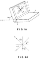
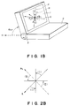
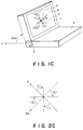
- Figures 1A - 1D are schematic perspective views of embodiments of the present invention.
- Figures 2A - 2D are explanatory views for illustrating regions (I) and (II) in relation to the rubbing direction in the present invention.
- Figure 3 is a sectional view of a liquid crystal panel as shown in Figures 1A - 1D.
- Figure 4 is an illustration of a liquid crystal molecular layer structure as shown in a liquid crystal cell as shown in Figure 3.
- Figure 5 is an explanatory view for illustrating regions (I) and (II) in relation to the rubbing direction in the display apparatus shown in Figure 1A.
- Figure 6 is a schematic view for explaining the manner of observation of tint of a liquid crystal panel.
- Figure 7 is an explanatory view for illustrating regions (I) and (II) in relation to the rubbing direction in another embodiment of the display apparatus shown in Figure 1A.
- Figure 8 is an explanatory view for illustrating regions (I) and (II) in relation to the rubbing direction in the display apparatus shown in Figure 1B.
- Figure 9 is an explanatory view for illustrating regions (I) and (II) in relation to the rubbing direction in the display apparatus shown in Figure 1C.
- Figure 10 is an explanatory view for illustrating regions (I) and (II) in relation to the rubbing direction in the display apparatus shown in Figure 1D.
- Figure 11 is an explanatory view for illustrating regions (I) and (II) in relation to the rubbing direction in another embodiment of the display apparatus shown in Figure 1D.
- Figures 2A and 2B each show a relationship between regions (I) and (II) and a rubbing direction in case where a pair of substrates have alignment films provided with rubbing axes which are parallel with each other and in the same oblique direction extending from upper right to lower left (or lower left to upper right).
- R denotes the rubbing direction
- R N denotes the direction intersecting perpendicularly to the rubbing direction
- (I) denotes a region (I)
- (II) denotes a region (II).
- Figure 2A shows an embodiment wherein the region (I) is set as a region defined by a clockwise angle of 45 degrees from the rubbing direction R
- Figure 2B shows an embodiment wherein the region (I) is set as a region defined by a counterclockwise angle of 45 degrees from the rubbing direction R.
- the rubbing is applied in an oblique direction of from upper right to lower left or from lower left to upper right.
- a viewing angle region of about 30 degrees from the panel opposite a region where a white display state abruptly changes from a yellowish white to a bluish white is deviated to the oblique direction, whereby the color irregularity accompanying head shaking is suppressed.
- the transmission axis of a first polarizer is set within the region (I) defined by a clockwise angle of 0 - 45 degrees from the oblique rubbing direction R
- the transmission axis of a second polarizer is set within a region (II) defined by a clockwise angle of 0 - 45 degrees from the direction intersecting perpendicularly to the oblique rubbing direction.
- the region (I) is set as a region defined by an angle spanning from a direction rotated clockwise by an apparent tilt angle ⁇ a to a direction rotated similarly clockwise by an angle of 45 degrees - ⁇ a, respectively, from the rubbing direction; the region (II) is similarly set as a region defined by an angle spanning from a direction rotated clockwise by the apparent tilt angle ⁇ a to a direction rotated clockwise by the angle of 45 degrees - ⁇ a, respectively, from the direction perpendicular to the rubbing direction; and the transmission axes of the first and second polarizers from angles including a smaller angle ⁇ AP satisfying the relation of 45° ⁇ ⁇ AP ⁇ 90°, preferably 75° ⁇ ⁇ AP ⁇ 90°.
- intersection angle ⁇ AP By setting the intersection angle ⁇ AP to a value smaller than 90 degrees in this way, i.e., by arranging the polarizers in a non-right angle cross nicol state, the region of causing a negative-positive inversion is kept away to a sufficiently remote region forming a viewing angle of 50 degrees or larger from the opposite.
- Figure 1A shows an appearance of an embodiment of the ferroelectric liquid crystal display apparatus according to the present invention
- Figure 3 is a sectional view of the liquid crystal panel contained therein.
- the display apparatus includes a liquid crystal panel 1, a manipulator 2 such as a keyboard, and an angle adjusting mechanism 3 for adjusting the angle of disposition of the liquid crystal panel 1 including a ferroelectric liquid crystal cell 10 (Figure 3) with respect to a horizontal plane.
- a backlight (not shown) for illuminating the liquid crystal panel 1 from the backside.
- R denotes the rubbing direction
- P denotes the transmission axis of a first polarizer (17a in Figure 3)
- A denotes the transmission axis of a second polarizer (17b in Figure 3)
- H denotes a horizontal direction
- ⁇ DP denotes the disposition angle of the liquid crystal cell 10.
- the liquid crystal panel 1 includes a ferroelectric liquid crystal cell 10 comprising substrates 11a, 11b having thereon transparent electrodes 12a, 12b, insulating films 13a, 13b coating the transparent electrodes 12a, 12b, alignment films 14a, 14b formed on the insulating films 13a, 13b, a ferroelectric liquid crystal (FLC) 15, and spacer beads 16, a polarizer (polarizer on the backlight side) 17a, and an analyzer (polarizer on the display side) 17b.
- a ferroelectric liquid crystal cell 10 comprising substrates 11a, 11b having thereon transparent electrodes 12a, 12b, insulating films 13a, 13b coating the transparent electrodes 12a, 12b, alignment films 14a, 14b formed on the insulating films 13a, 13b, a ferroelectric liquid crystal (FLC) 15, and spacer beads 16, a polarizer (polarizer on the backlight side) 17a, and an analyzer (polarizer on the display side) 17b.
- FLC ferroelectric liquid
- the liquid crystal panel 1 is composed by disposing the ferroelectric liquid crystal cell 10 which in turn is constituted by sandwiching the ferroelectric liquid crystal 15 between the pair of the substrates 17a and 17b respectively having the electrodes 12a, 12b and the alignment films 14a, 14b, between the pair of polarizers 17a, 17b.
- R denotes the directions of rubbing applied respectively to the alignment films 14a and 14b on the substrates 11a and 11b.
- the alignment films 14a and 14b of the liquid crystal panel 1 in Figure 1A were rubbed in parallel with each other in the same oblique direction forming an angle of 45 degrees with respect to the vertical direction and extending from upper right to lower left of a panel frame 6 shown in Figures 1, 2 and 5.
- the liquid crystal material used was a pyrimidine-type liquid crystal mixture and showed an apparent tilt anglel ⁇ a of 7 degrees.
- the apparent tilt angle ⁇ a used herein refers to a half of an angle formed between an average molecular axis direction ⁇ PO resultant after application of a positive polarity pulse to the liquid crystal and subsequent removal of the pulse and an average molecular axis direction ⁇ NO resultant after application of a negative polarity pulse to the liquid crystal and subsequent removal of the pulse.
- ⁇ a ( ⁇ PO - ⁇ NO )/2 .
- the transmission axis direction P of the polarizer 17a was set at a clockwise angle of 7 degrees from the rubbing direction R
- the transmission axis direction A of the analyzer 17b was set at a clockwise angle of 7 degrees from the direction perpendicular to the rubbing direction.
- Figure 7 shows another specific embodiment of the embodiment shown in Figure 2A.
- the smaller angle of intersection ⁇ AP between polarizer transmission axis P and the analyzer transmission axis A was set at 85 degrees to provide non-right angle cross nicols giving brighter states with respect to both display states.
- the negative-positive inversion region or boundary in the vertical direction could be increased from a viewing angle of about 50 degrees to about 70 degrees respectively from the opposite.
- the transmission axis of a first polarizer is set within the region (I) defined by a counterclockwise angle of 0 - 45 degrees from the oblique rubbing direction R
- the transmission axis of a second polarizer is set within a region (II) defined by a counterclockwise angle of 0 - 45 degrees from the direction intersecting perpendicularly to the oblique rubbing direction.
- the apparatus is constructed so as to allow adjustment of the disposition angle of the ferroelectric liquid crystal panel standing up from a horizontal plane, the display user can adjust the disposition angle to a position not causing a remarkable contrast change.
- the region (I) is set as a region defined by an angle spanning from a direction rotated counterclockwise by an apparent tilt angle ⁇ a to a direction rotated similarly counterclockwise by an angle of 45 degrees - ⁇ a, respectively, from the rubbing direction R; the region (II) is similarly set as a region defined by an angle spanning from a direction rotated counterclockwise by the apparent tilt angle ⁇ a to a direction rotated counterclockwise by the angle of 45 degrees - ⁇ a, respectively, from the direction R N perpendicular to the rubbing direction; and the transmission axes of the first and second polarizers from angles including a smaller angle ⁇ AP satisfying the relation of 45° ⁇ ⁇ AP ⁇ 90°, preferably 75° ⁇ ⁇ AP ⁇ 90°.
- FIG 1B shows an appearance of an embodiment of the ferroelectric liquid crystal display apparatus according to the present invention.
- the embodiment has entirely the same structure as the one explained with reference to Figure 1A except that the liquid crystal panel shown in Figure 2B is used instead of the one shown in Figure 2A.
- the contrast in a horizontal viewing angle region of ⁇ about 30 degrees from the opposite was set to a uniformly high value.
- the negative-positive inversion occurred at a horizontal viewing angle of 45 degrees or large.
- the smaller angle of intersection ⁇ AP between polarizer transmission axis P and the analyzer transmission axis A was set at 85 degrees to provide non-right angle cross nicols giving brighter states with respect to both display states.
- the negative-positive inversion region or boundary in the horizontal direction could be increased from a viewing angle of about 50 degrees to about 70 degrees respectively from the opposite.
- the alignment films 14a and 14b of the liquid crystal panel 1 in Figure 1B were rubbed in parallel with each other in the same oblique direction forming an angle of 45 degrees with respect to the vertical direction and extending from upper right to lower left of a panel frame 6 shown in Figures 1, 2 and 8.
- the liquid crystal material used was a pyrimidine-type liquid crystal mixture and showed an apparent tilt angle ⁇ a of 7 degrees.
- the transmission axis direction P of the polarizer 17a was set at a counterclockwise angle of 7 degrees from the rubbing direction R
- the transmission axis direction A of the analyzer 17b was set at a counterclockwise angle of 12 degrees from the direction perpendicular to the rubbing direction.
- Figures 2C and 2D each show a relationship between regions (I) and (II) and a rubbing direction in case where a pair of substrates have alignment films provided with rubbing axes which are parallel with each other and in the same oblique direction extending from lower right to upper left (or upper left to lower right).
- Figure 2C shows an embodiment wherein the region (I) is set as a region defined by a clockwise angle of 45 degrees from the rubbing direction R
- Figure 2D shows an embodiment wherein the region (I) is set as a region defined by a counterclockwise angle of 45 degrees from the rubbing direction R.
- the rubbing is applied in an oblique direction of from lower right to upper left or from upper left to lower right.
- a region where a white display state abruptly changes from a yellowish white to a bluish white is deviated to the oblique direction, whereby the color irregularity accompanying head shaking is suppressed.
- the transmission axis of a first polarizer is set within the region (I) defined by a clockwise angle of 0 - 45 degrees from the oblique rubbing direction R
- the transmission axis of a second polarizer is set within a region (II) defined by a clockwise angle of 0 - 45 degrees from the direction R N intersecting perpendicularly to the oblique rubbing direction.
- the apparatus is constructed so as to allow adjustment of the disposition angle of the ferroelectric liquid crystal panel standing up from a horizontal plane, the display user can adjust the disposition angle to a position not causing a remarkable contrast change.
- the region (I) is set as a region defined by an angle spanning from a direction rotated clockwise by an apparent tilt angle ⁇ a to a direction rotated similarly clockwise by an angle of 45 degrees - ⁇ a, respectively, from the rubbing direction; the region (II) is similarly set as a region defined by an angle spanning from a direction rotated clockwise by the apparent tilt angle ⁇ a to a direction rotated clockwise by the angle of 45 degrees - ⁇ a, respectively, from the direction perpendicular to the rubbing direction; and the transmission axes of the first and second polarizers from angles including a smaller angle ⁇ AP satisfying the relation of 45° ⁇ ⁇ AP ⁇ 90°, preferably 75° ⁇ ⁇ AP ⁇ 90°.
- FIG 1C shows an appearance of an embodiment of the ferroelectric liquid crystal display apparatus according to the present invention.
- the embodiment has entirely the same structure as the one explained with reference to Figure 1A except that the liquid crystal panel shown in Figure 2C is used instead of the one shown in Figure 2A.
- the alignment films 14a and 14b of the liquid crystal panel 1 in Figure 1C were rubbed in parallel with each other in the same oblique direction forming an angle of 45 degrees with respect to the vertical direction and extending from lower right to upper left of a panel frame 6 shown in Figures 1C, 2C and 9.
- the liquid crystal material used was a pyrimidine-type liquid crystal mixture and showed an apparent tilt angle ⁇ a of 7 degrees.
- the transmission axis direction P of the polarizer 17a was set at a clockwise angle of 7 degrees from the rubbing direction R
- the transmission axis direction A of the analyzer 17b was set at a clockwise angle of 7 degrees from the direction perpendicular to the rubbing direction.
- the white display state was controlled so that its yellowish white tint always faced the display user regardless of the positivity or negativity of spontaneous polarization P S or the directions of twist FLC molecules having a chevron splay structure at the upper and lower substrate boundaries.
- the contrast in a horizontal viewing region of ⁇ about 30 degrees from the opposite was set to a uniformly high value.
- the negative-positive inversion occurred at a horizontal viewing angle of 45 degrees or larger.
- the smaller angle of intersection ⁇ AP between polarizer transmission axis P and the analyzer transmission axis A was set at 85 degrees to provide non-right angle cross nicols giving brighter states with respect to both display states.
- the negative-positive inversion region or boundary in the horizontal direction could be increased from a viewing angle of about 50 degrees to about 70 degrees respectively from the opposite.
- the rubbing is applied in an oblique direction of from lower right to upper left or from upper left to lower right.
- a viewing angle region of about 30 degrees from the panel opposite a region where a white display state abruptly changes from a yellowish white to a bluish white is deviated to the oblique direction, whereby the color irregularity accompanying head shaking is suppressed.
- the transmission axis of a first polarizer is set within the region (I) defined by a counterclockwise angle of 0 - 45 degrees from the oblique rubbing direction R
- the transmission axis of a second polarizer is set within a region (II) defined by a counterclockwise angle of 0 - 45 degrees from the direction intersecting perpendicularly to the oblique rubbing direction.
- the region (I) is set as a region defined by an angle spanning from a direction rotated counterclockwise by an apparent tilt angle ⁇ a to a direction rotated similarly counterclockwise by an angle of 45 degrees - ⁇ a, respectively, from the rubbing direction; the region (II) is similarly set as a region defined by an angle spanning from a direction rotated counterclockwise by the apparent tilt angle ⁇ a to a direction rotated counterclockwise by the angle of 45 degrees - ⁇ a, respectively, from the direction perpendicular to the rubbing direction; and the transmission axes of the first and second polarizers from angles including a smaller angle ⁇ AP satisfying the relation of 45° ⁇ ⁇ AP ⁇ 90°, preferably 75° ⁇ ⁇ AP ⁇ 90°.
- the region of causing a negative-positive inversion is kept away to a sufficiently remote region forming a viewing angle of 50 degrees or larger from the opposite.
- FIG 1D shows an appearance of an embodiment of the ferroelectric liquid crystal display apparatus according to the present invention.
- the embodiment has entirely the same structure as the one explained with reference to Figure 1A except that the liquid crystal panel shown in Figure 2D is used instead of the one shown in Figure 2A.
- the alignment films 14a and 14b of the liquid crystal panel 1 in Figure 1D were rubbed in parallel with each other in the same oblique direction forming an angle of 45 degrees with respect to the vertical direction and extending from lower right to upper left of a panel frame 6 shown in Figures 1D, 2D and 10.
- the liquid crystal material used was a pyrimidine-type liquid crystal mixture and showed an apparent tilt angle ⁇ a of 7 degrees.
- the transmission axis direction P of the polarizer 17a was set at a counterclockwise angle of 7 degrees from the rubbing direction R
- the transmission axis direction A of the analyzer 17b was set at a counterclockwise angle of 7 degrees from the direction perpendicular to the rubbing direction.
- FIG 11 shows another specific embodiment of the embodiment shown in Figure 2D.
- the smaller angle of intersection ⁇ AP between polarizer transmission axis P and the analyzer transmission axis A was set at 85 degrees to provide non-right angle cross nicols giving brighter states with respect to both display states.
- the negative-positive inversion region or boundary in the vertical direction could be increased from a viewing angle of about 50 degrees to about 70 degrees respectively from the opposite.
- the present invention is not limited to the above-described embodiment but can be practiced by appropriately modifying the above embodiments.
- the polarizer 17a has been taken as a first polarizer and the analyzer 17b has been taken as a second polarizer in the above, whereas the analyzer 17b can constitute a first polarizer and the polarizer 17a can constitute a second polarizer.
- the liquid crystal panel 1 can be used in a position obtained by 180 degrees rotation thereof in the above embodiments.
Landscapes
- Physics & Mathematics (AREA)
- Chemical & Material Sciences (AREA)
- Crystallography & Structural Chemistry (AREA)
- Nonlinear Science (AREA)
- General Physics & Mathematics (AREA)
- Optics & Photonics (AREA)
- Engineering & Computer Science (AREA)
- Theoretical Computer Science (AREA)
- Liquid Crystal (AREA)
- Liquid Crystal Substances (AREA)
Claims (8)
- Appareil à cristaux liquides ferroélectriques, comportant :
un panneau (1) à cristaux liquides ferroélectriques disposé dans un angle (ϑDP) de disposition par rapport à un plan horizontal et comprenant deux substrats (11a, 11b) portant chacun une électrode (12a, 12b) et un film d'alignement (14a, 14b), au moins l'un desdits films d'alignement (14a, 14b) étant pourvu d'un axe d'orientation uniaxe (R), et un premier polariseur (17a) et un second polariseur (17b) ayant chacun un axe de transmission (P, A) et disposés pour encadrer ledit panneau (1) à cristaux liquides ferroélectriques ;
dans lequel ledit axe d'orientation uniaxe (R) est disposé de façon à s'étendre obliquement sur ledit film d'alignement (14a, 14b) depuis la partie supérieure droite vers la partie inférieure gauche ou depuis la partie inférieure gauche vers la partie supérieure droite, comme vu dans une direction normale d'observation dudit panneau (1) à cristaux liquides ferroélectriques, par un observateur placé en face dudit panneau (1) d'affichage à cristaux liquides ferroélectriques ;
ledit axe (P) de transmission dudit premier polariseur (17a) est placé dans une région (I) définie par un angle de 45° à partir, dans le sens des aiguilles d'une montre, de la direction dudit axe (R) d'orientation uniaxe s'étendant obliquement ;
ledit axe (A) de transmission dudit second polariseur (17b) est placé dans une région (II) définie par un angle de 45° à partir, dans le sens des aiguilles d'une montre, de la direction perpendiculaire à la direction dudit axe d'orientation uniaxe (R) s'étendant obliquement ; et
ledit appareil comprend en outre un mécanisme (3) pour régler ledit angle (ϑDP) de disposition dudit panneau (1) à cristaux liquides ferroélectriques par rapport audit plan horizontal. - Appareil à cristaux liquides ferroélectriques, comportant :
un panneau (1) à cristaux liquides ferroélectriques disposé dans un angle (ϑDP) de disposition par rapport à un plan horizontal et comprenant deux substrats (11a, 11b) portant chacun une électrode (12a, 12b) et un film d'alignement (14a, 14b), au moins l'un desdits films d'alignement (14a, 14b) étant pourvu d'un axe d'orientation uniaxe (R), et un premier polariseur (17a) et un second polariseur (17b) ayant chacun un axe de transmission (P, A) et disposés pour encadrer ledit panneau (1) à cristaux liquides ferroélectriques ;
dans lequel ledit axe d'orientation uniaxe (R) est disposé de façon à s'étendre obliquement sur ledit film d'alignement (14a, 14b) depuis la partie supérieure droite vers la partie inférieure gauche ou depuis la partie inférieure gauche vers la partie supérieure droite, comme vu dans une direction normale d'observation dudit panneau (1) à cristaux liquides ferroélectriques, par un observateur placé en face dudit panneau (1) à cristaux liquides ferroélectriques ;
ledit axe (P) de transmission dudit premier polariseur (17a) est placé dans une région (I) définie par un angle de 45° à partir, dans le sens inverse de celui des aiguilles d'une montre, de la direction dudit axe (R) d'orientation uniaxe s'étendant obliquement ;
ledit axe (A) de transmission dudit second polariseur (17b) est placé dans une région (II) définie par un angle de 45° à partir, dans le sens inverse de celui des aiguilles d'une montre, de la direction perpendiculaire à la direction dudit axe d'orientation uniaxe (R) s'étendant obliquement ; et
ledit appareil comprend en outre un mécanisme (3) pour régler ledit angle (ϑDP) de disposition dudit panneau (1) à cristaux liquides ferroélectriques par rapport audit plan horizontal. - Appareil à cristaux liquides ferroélectriques, comportant :
un panneau (1) à cristaux liquides ferroélectriques disposé dans un angle (ϑDP) de disposition par rapport à un plan horizontal et comprenant deux substrats (11a, 11b) portant chacun une électrode (12a, 12b) et un film d'alignement (14a, 14b), au moins l'un desdits films d'alignement (14a, 14b) étant pourvu d'un axe d'orientation uniaxe (R), et un premier polariseur (17a) et un second polariseur (17b) ayant chacun un axe de transmission (P, A) et disposés pour encadrer ledit panneau (1) à cristaux liquides ferroélectriques ;
dans lequel ledit axe d'orientation uniaxe (R) est disposé de façon à s'étendre obliquement sur ledit film d'alignement (14a, 14b) depuis une partie inférieure droite vers une partie supérieure gauche ou depuis une partie supérieure gauche vers une partie inférieure droite, comme vu dans une direction normale d'observation dudit panneau (1) à cristaux liquides ferroélectriques, par un observateur placé devant ledit panneau (1) à cristaux liquides ferroélectriques ;
ledit axe (P) de transmission dudit premier polariseur (17a) est placé dans une région (I) définie par un angle de 45° à partir, dans le sens inverse de celui des aiguilles d'une montre, de la direction dudit axe (R) d'orientation uniaxe s'étendant obliquement ;
ledit axe (A) de transmission dudit second polariseur (17b) est placé dans une région (II) définie par un angle de 45° à partir, dans le sens inverse de celui des aiguilles d'une montre, de la direction perpendiculaire à la direction dudit axe d'orientation uniaxe (R) s'étendant obliquement ; et
ledit appareil comprend en outre un mécanisme (3) pour régler ledit angle (ϑDP) de disposition dudit panneau (1) à cristaux liquides ferroélectriques par rapport audit plan horizontal. - Appareil à cristaux liquides ferroélectriques, comportant :
un panneau (1) à cristaux liquides ferroélectriques disposé dans un angle (ϑDP) de disposition par rapport à un plan horizontal et comprenant deux substrats (11a, 11b) portant chacun une électrode (12a, 12b) et un film d'alignement (14a, 14b), au moins l'un desdits films d'alignement (14a, 14b) étant pourvu d'un axe d'orientation uniaxe (R), et un premier polariseur (17a) et un second polariseur (17b) ayant chacun un axe de transmission (P, A) et disposés pour encadrer ledit panneau (1) à cristaux liquides ferroélectriques ;
dans lequel ledit axe unique d'orientation (R) est disposé de façon à s'étendre obliquement sur ledit film d'alignement (14a, 14b) depuis une partie inférieure droite vers une partie supérieure gauche ou depuis une partie supérieure gauche vers une partie inférieure droite, comme vu dans une direction normale d'observation dudit panneau (1) à cristaux liquides ferroélectriques, par un observateur placé devant ledit panneau (1) à cristaux liquides ferroélectriques ;
ledit axe (P) de transmission dudit premier polariseur (17a) est placé dans une région (I) définie par un angle de 45° à partir, dans le sens des aiguilles d'une montre, de la direction dudit axe (R) d'orientation uniaxe s'étendant obliquement ;
ledit axe (A) de transmission dudit second polariseur (17b) est placé dans une région (II) définie par un angle de 45° à partir, dans le sens des aiguilles d'une montre, de la direction perpendiculaire à la direction dudit axe d'orientation (R) uniaxe s'étendant obliquement ; et
ledit appareil comprend en outre un mécanisme (3) pour régler ledit angle (ϑDP) de disposition dudit panneau (1) à cristaux liquides ferroélectriques par rapport audit plan horizontal. - Appareil selon la revendication 1 ou 4, dans lequel ladite région (I) est définie par un angle s'étendant depuis une direction tournée dans le sens des aiguilles d'une montre d'un angle ϑa d'inclinaison apparente jusqu'à une direction tournée dans le sens des aiguilles d'une montre d'un angle de 45°-ϑa, respectivement, à partir de la direction dudit axe (R) d'orientation uniaxe ;
ladite région (II) est définie par un angle s'étendant depuis une direction tournée dans le sens des aiguilles d'une montre de l'angle ϑa d'inclinaison apparente jusqu'à une direction tournée dans le sens des aiguilles d'une montre dudit angle de 45⁰-ϑa, respectivement, à partir de la direction perpendiculaire à la direction dudit axe (R) d'orientation uniaxe ; et
ledit axe (P) de transmission dudit premier polariseur (17a) et ledit axe (A) de transmission dudit second polariseur (17b) sont disposés de façon à former des angles d'intersection comprenant un angle inférieur (ϑAP) satisfaisant la relation 45° < ϑAP < 90°. - Appareil selon la revendication 2 ou 3, dans lequel ladite région (I) est définie par un angle s'étendant depuis une direction tournée dans le sens inverse de celui des aiguilles d'une montre d'un angle (ϑa) d'inclinaison apparente jusqu'à une direction tournée, dans le sens inverse de celui des aiguilles d'une montre, d'un angle de 45°-ϑa, respectivement, à partir de la direction dudit axe (R) d'orientation uniaxe ;
ladite région (II) est définie par un angle s'étendant depuis une direction, tournée dans le sens inverse de celui des aiguilles d'une montre, de l'angle (ϑa) d'inclinaison apparente jusqu'à une direction tournée dans le sens inverse de celui des aiguilles d'une montre dudit angle de 45°-ϑa, respectivement, à partir de la direction perpendiculaire à la direction dudit axe (R) d'orientation uniaxe ; et
ledit axe (P) de transmission dudit premier polariseur (17a) et ledit axe (A) de transmission dudit second polariseur (17b) sont disposés de façon à former des angles d'intersection comprenant un angle (ϑAP) inférieur satisfaisant la relation 45° < ϑAP < 90°. - Appareil selon la revdndication 5 ou 6, dans lequel ledit angle inférieur (ϑAP) entre lesdits axes de transmission (P, A) desdits premier et second polariseurs (17a, 17b) satisfait la relation 75° < ϑAP < 90°.
- Appareil selon l'une quelconque des revendications précédentes 1 à 4, dans lequel ledit axe (R) d'orientation uniaxe est formé par frottement.
Applications Claiming Priority (8)
| Application Number | Priority Date | Filing Date | Title |
|---|---|---|---|
| JP242576/88 | 1988-09-29 | ||
| JP63242574A JP2640250B2 (ja) | 1988-09-29 | 1988-09-29 | 強誘電性液晶表示装置 |
| JP242574/88 | 1988-09-29 | ||
| JP63242573A JP2640249B2 (ja) | 1988-09-29 | 1988-09-29 | 強誘電性液晶表示装置 |
| JP242575/88 | 1988-09-29 | ||
| JP63242576A JP2640252B2 (ja) | 1988-09-29 | 1988-09-29 | 強誘電性液晶表示装置 |
| JP242573/88 | 1988-09-29 | ||
| JP63242575A JP2640251B2 (ja) | 1988-09-29 | 1988-09-29 | 強誘電性液晶表示装置 |
Publications (3)
| Publication Number | Publication Date |
|---|---|
| EP0361472A2 EP0361472A2 (fr) | 1990-04-04 |
| EP0361472A3 EP0361472A3 (en) | 1990-10-24 |
| EP0361472B1 true EP0361472B1 (fr) | 1995-08-30 |
Family
ID=27477893
Family Applications (1)
| Application Number | Title | Priority Date | Filing Date |
|---|---|---|---|
| EP89117950A Expired - Lifetime EP0361472B1 (fr) | 1988-09-29 | 1989-09-28 | Dispositif à cristal liquide ferro-électrique |
Country Status (5)
| Country | Link |
|---|---|
| US (1) | US5082352A (fr) |
| EP (1) | EP0361472B1 (fr) |
| AT (1) | ATE127240T1 (fr) |
| DE (1) | DE68924028T2 (fr) |
| ES (1) | ES2076182T3 (fr) |
Families Citing this family (8)
| Publication number | Priority date | Publication date | Assignee | Title |
|---|---|---|---|---|
| DE4012750A1 (de) * | 1990-04-21 | 1991-10-24 | Hoechst Ag | Ferroelektrisches fluessigkristalldisplay mit hohem kontrast und hoher helligkeit |
| JP3076085B2 (ja) * | 1991-04-27 | 2000-08-14 | 株式会社半導体エネルギー研究所 | 液晶電気光学装置 |
| GB9127316D0 (en) * | 1991-12-23 | 1992-02-19 | Secr Defence | Ferroelectric liquid crystal display device(improved contrast) |
| GB2266966B (en) * | 1992-05-15 | 1995-10-25 | Marconi Gec Ltd | Display devices |
| US5842672A (en) * | 1996-06-07 | 1998-12-01 | Ergotron, Inc. | Mounting system for flat panel display, keyboard and stand |
| KR100375732B1 (ko) * | 1997-11-25 | 2004-10-14 | 비오이 하이디스 테크놀로지 주식회사 | 액정표시장치 |
| US6670937B1 (en) * | 1999-03-01 | 2003-12-30 | Canon Kabushiki Kaisha | Liquid crystal display apparatus |
| TWI440936B (zh) * | 2011-07-01 | 2014-06-11 | Au Optronics Corp | 透鏡膜及其製造方法 |
Family Cites Families (10)
| Publication number | Priority date | Publication date | Assignee | Title |
|---|---|---|---|---|
| US4563059A (en) * | 1983-01-10 | 1986-01-07 | Clark Noel A | Surface stabilized ferroelectric liquid crystal devices |
| US4367924A (en) * | 1980-01-08 | 1983-01-11 | Clark Noel A | Chiral smectic C or H liquid crystal electro-optical device |
| JPS58173718A (ja) * | 1982-04-07 | 1983-10-12 | Hitachi Ltd | 液晶光変調素子およびその製造方法 |
| US4634228A (en) * | 1984-05-01 | 1987-01-06 | Hitachi, Ltd. | Ferroelectric liquid crystal cell with rubbed polyimide alignment layer |
| JPS6167832A (ja) * | 1984-09-12 | 1986-04-08 | Canon Inc | 液晶素子 |
| JPS61137127A (ja) * | 1984-12-07 | 1986-06-24 | Hitachi Ltd | 液晶表示素子 |
| US4820026A (en) * | 1986-03-20 | 1989-04-11 | Canon Kabushiki Kaisha | Ferroelectric liquid crystal device with modified polyvinyl alcohol alignment film |
| US4879059A (en) * | 1986-09-02 | 1989-11-07 | Canon Kabushiki Kaisha | Liquid crystal device |
| EP0263225B1 (fr) * | 1986-10-07 | 1992-04-08 | S.A.R.L. S.T. Lagerwall | Dispositif pour la modulation électro-optique submicroseconde dans un cristal liquide présentant une phase smectique A |
| US4932758A (en) * | 1987-09-17 | 1990-06-12 | Canon Kabushiki Kaisha | Ferroelectric smectic liquid crystal device having a bistable alignment state providing two stable orientation states |
-
1989
- 1989-09-27 US US07/413,232 patent/US5082352A/en not_active Expired - Lifetime
- 1989-09-28 AT AT89117950T patent/ATE127240T1/de not_active IP Right Cessation
- 1989-09-28 DE DE68924028T patent/DE68924028T2/de not_active Expired - Fee Related
- 1989-09-28 EP EP89117950A patent/EP0361472B1/fr not_active Expired - Lifetime
- 1989-09-28 ES ES89117950T patent/ES2076182T3/es not_active Expired - Lifetime
Also Published As
| Publication number | Publication date |
|---|---|
| EP0361472A2 (fr) | 1990-04-04 |
| DE68924028T2 (de) | 1996-02-22 |
| EP0361472A3 (en) | 1990-10-24 |
| ATE127240T1 (de) | 1995-09-15 |
| DE68924028D1 (de) | 1995-10-05 |
| US5082352A (en) | 1992-01-21 |
| ES2076182T3 (es) | 1995-11-01 |
Similar Documents
| Publication | Publication Date | Title |
|---|---|---|
| EP0455160B1 (fr) | Dispositif d'affichage à cristal liquide | |
| EP0391305A2 (fr) | Appareil à cristaux liquides | |
| EP0610923A2 (fr) | Dispositif d'affichage à cristal liquide avec structure à multi-domaines | |
| JPH09197408A (ja) | 光を用いたツイストネマチック液晶セルの製造方法 | |
| US5495351A (en) | Liquid crystal device with two monostable liquid crystal cells | |
| JPH06331979A (ja) | ノーマリ・ホワイト液晶ディスプレイ、およびその位相遅れを補償するための方法 | |
| US7808604B2 (en) | Liquid crystal display device of in-plane switching mode, method of fabricating the same, and method of driving the same | |
| US6067142A (en) | Vertically aligned pi-cell LCD having on-state with mid-plane molecules perpendicular to the substrates | |
| EP0361472B1 (fr) | Dispositif à cristal liquide ferro-électrique | |
| JPH07253578A (ja) | 液晶表示装置 | |
| JPH04247428A (ja) | カイラルスメクチック液晶素子 | |
| US5682217A (en) | Liquid crystal display device in which no sticking phenomenon occurs with high contrast | |
| US5109291A (en) | Ferroelectric liquid crystal optical modulation device having non-pixel portions controlled to a predetermined orientation state | |
| JP3091603B2 (ja) | 液晶表示装置 | |
| EP0556603A1 (fr) | Dispositif à cristal liquide et dispositif d'affichage | |
| CN100370353C (zh) | 板内切换模式液晶显示器件及其制造方法和驱动方法 | |
| JPH05173137A (ja) | 液晶表示装置 | |
| JPH04349424A (ja) | 液晶表示素子および光学異方素子 | |
| JP3042424B2 (ja) | 表示素子及びその製造方法 | |
| KR100802306B1 (ko) | 액정 표시 장치 및 그 제조방법 | |
| JP2775528B2 (ja) | カイラルスメクチック液晶素子 | |
| US7307678B2 (en) | Liquid crystal display and fabricating method thereof | |
| JP2956953B2 (ja) | 液晶表示装置およびその製造方法 | |
| JP2000275684A (ja) | 液晶素子およびそれを用いた液晶装置 | |
| JPH0293428A (ja) | 強誘電性液晶表示装置 |
Legal Events
| Date | Code | Title | Description |
|---|---|---|---|
| PUAI | Public reference made under article 153(3) epc to a published international application that has entered the european phase |
Free format text: ORIGINAL CODE: 0009012 |
|
| 17P | Request for examination filed |
Effective date: 19890928 |
|
| AK | Designated contracting states |
Kind code of ref document: A2 Designated state(s): AT BE CH DE ES FR GB GR IT LI LU NL SE |
|
| PUAL | Search report despatched |
Free format text: ORIGINAL CODE: 0009013 |
|
| AK | Designated contracting states |
Kind code of ref document: A3 Designated state(s): AT BE CH DE ES FR GB GR IT LI LU NL SE |
|
| 17Q | First examination report despatched |
Effective date: 19930104 |
|
| GRAA | (expected) grant |
Free format text: ORIGINAL CODE: 0009210 |
|
| AK | Designated contracting states |
Kind code of ref document: B1 Designated state(s): AT BE CH DE ES FR GB GR IT LI LU NL SE |
|
| PG25 | Lapsed in a contracting state [announced via postgrant information from national office to epo] |
Ref country code: GR Free format text: LAPSE BECAUSE OF FAILURE TO SUBMIT A TRANSLATION OF THE DESCRIPTION OR TO PAY THE FEE WITHIN THE PRESCRIBED TIME-LIMIT Effective date: 19950830 Ref country code: BE Effective date: 19950830 Ref country code: AT Effective date: 19950830 |
|
| REF | Corresponds to: |
Ref document number: 127240 Country of ref document: AT Date of ref document: 19950915 Kind code of ref document: T |
|
| PG25 | Lapsed in a contracting state [announced via postgrant information from national office to epo] |
Ref country code: LU Free format text: LAPSE BECAUSE OF NON-PAYMENT OF DUE FEES Effective date: 19950930 |
|
| PGFP | Annual fee paid to national office [announced via postgrant information from national office to epo] |
Ref country code: CH Payment date: 19950930 Year of fee payment: 7 |
|
| REF | Corresponds to: |
Ref document number: 68924028 Country of ref document: DE Date of ref document: 19951005 |
|
| ET | Fr: translation filed | ||
| REG | Reference to a national code |
Ref country code: ES Ref legal event code: FG2A Ref document number: 2076182 Country of ref document: ES Kind code of ref document: T3 |
|
| REG | Reference to a national code |
Ref country code: CH Ref legal event code: PL |
|
| ITF | It: translation for a ep patent filed | ||
| PLBE | No opposition filed within time limit |
Free format text: ORIGINAL CODE: 0009261 |
|
| STAA | Information on the status of an ep patent application or granted ep patent |
Free format text: STATUS: NO OPPOSITION FILED WITHIN TIME LIMIT |
|
| 26N | No opposition filed | ||
| PG25 | Lapsed in a contracting state [announced via postgrant information from national office to epo] |
Ref country code: LI Free format text: LAPSE BECAUSE OF FAILURE TO SUBMIT A TRANSLATION OF THE DESCRIPTION OR TO PAY THE FEE WITHIN THE PRESCRIBED TIME-LIMIT Effective date: 19960930 Ref country code: CH Free format text: LAPSE BECAUSE OF FAILURE TO SUBMIT A TRANSLATION OF THE DESCRIPTION OR TO PAY THE FEE WITHIN THE PRESCRIBED TIME-LIMIT Effective date: 19960930 |
|
| REG | Reference to a national code |
Ref country code: GB Ref legal event code: IF02 |
|
| PGFP | Annual fee paid to national office [announced via postgrant information from national office to epo] |
Ref country code: SE Payment date: 20020904 Year of fee payment: 14 |
|
| PGFP | Annual fee paid to national office [announced via postgrant information from national office to epo] |
Ref country code: FR Payment date: 20020910 Year of fee payment: 14 |
|
| PGFP | Annual fee paid to national office [announced via postgrant information from national office to epo] |
Ref country code: GB Payment date: 20020925 Year of fee payment: 14 |
|
| PGFP | Annual fee paid to national office [announced via postgrant information from national office to epo] |
Ref country code: ES Payment date: 20020927 Year of fee payment: 14 |
|
| PGFP | Annual fee paid to national office [announced via postgrant information from national office to epo] |
Ref country code: NL Payment date: 20020930 Year of fee payment: 14 |
|
| PGFP | Annual fee paid to national office [announced via postgrant information from national office to epo] |
Ref country code: DE Payment date: 20021002 Year of fee payment: 14 |
|
| PG25 | Lapsed in a contracting state [announced via postgrant information from national office to epo] |
Ref country code: GB Free format text: LAPSE BECAUSE OF NON-PAYMENT OF DUE FEES Effective date: 20030928 |
|
| PG25 | Lapsed in a contracting state [announced via postgrant information from national office to epo] |
Ref country code: SE Free format text: LAPSE BECAUSE OF NON-PAYMENT OF DUE FEES Effective date: 20030929 Ref country code: ES Free format text: LAPSE BECAUSE OF NON-PAYMENT OF DUE FEES Effective date: 20030929 |
|
| PG25 | Lapsed in a contracting state [announced via postgrant information from national office to epo] |
Ref country code: NL Free format text: LAPSE BECAUSE OF NON-PAYMENT OF DUE FEES Effective date: 20040401 Ref country code: DE Free format text: LAPSE BECAUSE OF NON-PAYMENT OF DUE FEES Effective date: 20040401 |
|
| EUG | Se: european patent has lapsed | ||
| GBPC | Gb: european patent ceased through non-payment of renewal fee |
Effective date: 20030928 |
|
| PG25 | Lapsed in a contracting state [announced via postgrant information from national office to epo] |
Ref country code: FR Free format text: LAPSE BECAUSE OF NON-PAYMENT OF DUE FEES Effective date: 20040528 |
|
| NLV4 | Nl: lapsed or anulled due to non-payment of the annual fee |
Effective date: 20040401 |
|
| REG | Reference to a national code |
Ref country code: FR Ref legal event code: ST |
|
| REG | Reference to a national code |
Ref country code: ES Ref legal event code: FD2A Effective date: 20030929 |
|
| PG25 | Lapsed in a contracting state [announced via postgrant information from national office to epo] |
Ref country code: IT Free format text: LAPSE BECAUSE OF NON-PAYMENT OF DUE FEES;WARNING: LAPSES OF ITALIAN PATENTS WITH EFFECTIVE DATE BEFORE 2007 MAY HAVE OCCURRED AT ANY TIME BEFORE 2007. THE CORRECT EFFECTIVE DATE MAY BE DIFFERENT FROM THE ONE RECORDED. Effective date: 20050928 |