EP0361517B1 - Herzschrittmacher mit adaptiver Schrittfrequenz - Google Patents
Herzschrittmacher mit adaptiver Schrittfrequenz Download PDFInfo
- Publication number
- EP0361517B1 EP0361517B1 EP89118071A EP89118071A EP0361517B1 EP 0361517 B1 EP0361517 B1 EP 0361517B1 EP 89118071 A EP89118071 A EP 89118071A EP 89118071 A EP89118071 A EP 89118071A EP 0361517 B1 EP0361517 B1 EP 0361517B1
- Authority
- EP
- European Patent Office
- Prior art keywords
- rate
- pacing
- slope
- url
- pacemaker
- Prior art date
- Legal status (The legal status is an assumption and is not a legal conclusion. Google has not performed a legal analysis and makes no representation as to the accuracy of the status listed.)
- Expired - Lifetime
Links
- 230000003044 adaptive effect Effects 0.000 title claims description 9
- 230000000747 cardiac effect Effects 0.000 title description 3
- 238000012544 monitoring process Methods 0.000 claims description 5
- 230000002269 spontaneous effect Effects 0.000 claims description 5
- 230000003247 decreasing effect Effects 0.000 claims description 4
- 238000004904 shortening Methods 0.000 claims description 2
- 230000002401 inhibitory effect Effects 0.000 claims 1
- 230000006870 function Effects 0.000 description 29
- 238000010586 diagram Methods 0.000 description 17
- 230000001746 atrial effect Effects 0.000 description 11
- 230000004044 response Effects 0.000 description 11
- 230000006978 adaptation Effects 0.000 description 7
- 230000002861 ventricular Effects 0.000 description 7
- 230000000694 effects Effects 0.000 description 6
- 102100026827 Protein associated with UVRAG as autophagy enhancer Human genes 0.000 description 5
- 101710102978 Protein associated with UVRAG as autophagy enhancer Proteins 0.000 description 5
- 238000000034 method Methods 0.000 description 5
- 102000003712 Complement factor B Human genes 0.000 description 4
- 108090000056 Complement factor B Proteins 0.000 description 4
- 238000013459 approach Methods 0.000 description 4
- 238000005259 measurement Methods 0.000 description 4
- 238000012545 processing Methods 0.000 description 4
- 230000009977 dual effect Effects 0.000 description 3
- 230000000763 evoking effect Effects 0.000 description 3
- 230000007774 longterm Effects 0.000 description 2
- 230000002503 metabolic effect Effects 0.000 description 2
- 239000008280 blood Substances 0.000 description 1
- 210000004369 blood Anatomy 0.000 description 1
- 238000004364 calculation method Methods 0.000 description 1
- 230000001419 dependent effect Effects 0.000 description 1
- 210000002837 heart atrium Anatomy 0.000 description 1
- 230000005764 inhibitory process Effects 0.000 description 1
- 238000011835 investigation Methods 0.000 description 1
- 230000000750 progressive effect Effects 0.000 description 1
- 230000029058 respiratory gaseous exchange Effects 0.000 description 1
- 230000024977 response to activity Effects 0.000 description 1
- 230000004043 responsiveness Effects 0.000 description 1
- 230000000284 resting effect Effects 0.000 description 1
- 230000001360 synchronised effect Effects 0.000 description 1
- 238000012360 testing method Methods 0.000 description 1
Images




Classifications
-
- A—HUMAN NECESSITIES
- A61—MEDICAL OR VETERINARY SCIENCE; HYGIENE
- A61N—ELECTROTHERAPY; MAGNETOTHERAPY; RADIATION THERAPY; ULTRASOUND THERAPY
- A61N1/00—Electrotherapy; Circuits therefor
- A61N1/18—Applying electric currents by contact electrodes
- A61N1/32—Applying electric currents by contact electrodes alternating or intermittent currents
- A61N1/36—Applying electric currents by contact electrodes alternating or intermittent currents for stimulation
- A61N1/362—Heart stimulators
- A61N1/365—Heart stimulators controlled by a physiological parameter, e.g. heart potential
- A61N1/36585—Heart stimulators controlled by a physiological parameter, e.g. heart potential controlled by two or more physical parameters
Definitions
- This invention relates to cardiac pacemakers and, in particular, rate responsive pacemakers having means for adapting the correlation between a monitored patient variable and indicated pacing rate as a function of sensed patient history.
- Atrial-based pacers i.e., atrial synchronous or atrial sequential pacers
- DDD pacemakers are dual chamber devices that require a second lead to be positioned in the atrium, and further are not satisfactory for patients with certain cardiac conditions.
- a number of indicators other than the atrial rate have been suggested as suitable for determining the optimal pacing rate in patients where DDD pacing is not indicated.
- the first commercially available form of single charge rate responsive pacemaker was the QT driven rate responsive pacemaker, marketed by the assignee of this invention. See U.S. Patent No. 4,228,803, to Rickards. Subsequently, other pacemakers utilizing other monitored variables have been introduced commercially, the best known example being the Activitrax model manufactured by Medtronic, Inc.
- Any rate responsive pacemaker incorporates a sensor adapted to sense a patient's variable which indicates, or reflects the patient's needs at any given moment, and which provides both quantitative and progressive information.
- the sensor is the same lead that delivers the pacing pulses. Following delivery of a pacing pulse, it senses the stimulus-evoked T-wave, and provides an electrical signal which can be compared in the time domain to the stimulus pulse, thus providing the QT time interval information.
- Whatever sensor is used for sensing an indication of physiological demand, in order to be useful in a modern implantable pacemaker, it must have long term stability and reliability.
- the general structure of a rate responsive pacemaker also includes a means for carrying out an algorithm by which the pacemaker determines the indicated pacing rate on the basis of information delivered by the sensor.
- the function of the algorithm is to provide a correspondence, or correlation between the sensed indicator variable and the pacing rate, so that the pacemaker ist accurately responsive to the monitored information.
- the algorithm determines the change in pacing rate per ms change in the stimulus-T interval, which is defined as the slope. Correct programming of the slope, and accurate processing by the pacemaker are seen to be crucial factors in obtaining optimal pacemaker functions. Intially, the slope, or relationship between QT interval and pacing rate, was fixed. Recent investigations into the relationship between the QT interval and the desired pacing rate have indicated that the slope should be variable, i.e., there should be means for automatic adaptation of the slope as a function of patient history, in order to maintain optimal long-term rate response, even under changing circumstances.
- rate responsive pacemakers namely that the correlation data between the monitored patient variable or variables and the desired pacing rate generally should be dynamic and subject to variation from patient to patient and as a function of patient history. Accordingly, there is a need in rate responsive pacemakers for implementation of automatic adaptation of the slope, or a pacing rate/indicator variable characteristic.
- Document EP-A-0 256 617 discloses a rate adaptive pacemaker as defined in the preamble of claim 1, in which one input to the control algorithm is a function of a varying reference temperature.
- an adaptive rate responsive pacemaker system as defined in claim 1, which in particular has a generator for generating pacing pulses at a controlled pacing rate, means for monitoring at least one patient variable correlative of desired heart rate, e.g., QT interval, and means for adjusting the function which relates the rate to said variable so that the correlation (slope) of the pacing rate and the patient variable is adaptive to actual patient conditions.
- the value of the slope (ratio of change in pacing interval to change in sensed input variable) at a lower rate limit (LRL) and upper rate limit (URL) is corrected in accordance with patient conditions or history, and the dynamic slope between LRL and URL is automatically adjusted to fit in between those limits.
- An external programmer can be used to make changes in the parameters that affect rate, such as LRL and URL.
- the apparatus of the invention are adaptable to rate control in DDD mode, as well as VVI mode.
- FIG. 1 there is shown a block diagram indicating conceptually the components of a rate adaptive pacemaker.
- a single chamber rate controlled pacemaker is illustrated as the preferred embodiment, the method of the invention is adaptable to control in a dual chamber pacemaker as well.
- a lead or sensor 30 is represented for deriving patient information.
- one or more sensors may be utilized to detect one or more patient variables indicative of patient demand for heart rate.
- the sensor 30 is integral with the lead going into the ventricle, and senses the T wave response, whereby the QT interval may be obtained.
- Other sensors for sensing other patient variables including mechanical movement, respiration rate, blood pH, temperature, etc.
- the input from the sensor or sensors 30 is communicated to the implantable pacemaker 32.
- the sensor information is passed through conventional signal processing 34 to place it into suitable form for further use in the logic circuitry.
- the output of the signal processing circuit, in the QT embodiment of this invention is transmitted to on demand logic circuitry 36, for generating control signals for controlling the generation of stimulus pulses in the absence of natural heartbeats, in a manner well knwon in the art.
- the output of on demand logic block 36 is transmitted to pulse generator 42, which provides the pacemaker output pulses.
- the output pulses are delivered to a pacing lead 43, which for the QT case is lead 30.
- the output of signal processing circuit 34 which includes indications of the T wave, is inputted to rate logic circuit 37 for determining the timing of the T wave relative to the delivered pulse signal, the timing of the latter being is provided from pulse generator block 42.
- the rate logic circuitry also provides means for determining the desired pacing rate as a function of QT, or other sensed variable, in a manner described in more detail hereinbelow.
- the output of rate logic circuit 37 is transmitted to rate adjust circuit 38, which generates an appropriate control signal which is transmitted to pulse generator 42, to control generator 42 to deliver pulses at a rate, or pacing interval, corresponding to the output of rate logic circuit 37.
- rate logic means 37 preferably includes stored data correlating values of QT interval with respective values of pacing interval.
- rate logic block 37 provides an output that corresponds to a determined pacing interval at which the pacemaker paces the patient in response to the detected QT interval.
- equivalent means are incorporated for generating the rate logic and rate adjust circuits.
- the functions of blocks 36, 37, and 38 may be carried out in a CPU or microprocessor, as disclosed in one or more of the referenced patents.
- the microprocessor 40 also contains memory for storing parameter data, which data is used in determining rate in a manner discussed hereinbelow.
- a graph depicting generally how QT interval (ms) varies as a function of pacing interval (ms) due to physiological variables.
- QT interval as an indicator is influenced by both heart rate alone (which can be seen when the patient is at rest) and also by patient demand, e.g., when a patient undergoes exercise.
- the relationship between pacing interval and QT interval is a function of two factors, i.e., patient metabolic demand such is induced by exercising, and also the heart rate itself.
- the resultant graph is seen to be nonlinear, representing a nonlinear slope which is defined as incremental change in pacing interval per incremental change in QT. It is seen that at high pacing intervals, corresponding to a lower rate, the variation of slope is greater, whereas at lower pacing intervals (corresponding to higher rates) the variation of slope is less. This results from the fact that when a higher rate is implemented by the pacemaker, the shorter P. I. tends to induce a further decrease in QT beyond what was initially indicated by the body's demands. In practice, the degree of QT interval shortening is least at long pacing intervals. If this is not compensated for, there may result a delay before a significant increase in pacing rate is seen after the commencement of exercise in some patients. Further, by lowering the slope as rate is increased, the pacemaker is not driven directly to URL too quickly.
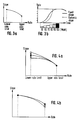
- Fig. 3(a) there is shown a representation of slope vs. rate which represents basically the same information as set forth in Fig.2, and shows that the desired slope is not constant, but is variable or dynamic. Note that the slope at LRL is higher than at URL, meaning that at lower rates the change in pacing interval for incremental changes in QT is made greater, while it is less at higher rates.
- Fig. 3(b) there is shown a representation of pacemaker controlled rate as a function of time for the QT driven embodiment, where the patient is undergoing exercise as indicated. Two curves are shown, one for a fixed (constant) slope, and one for a lonlinear or dynamic slope.
- the implemented variation in slope at the lower rate limit (LRL) is illustrated in a general manner for a pacemaker system that is rate-responsive.
- the slope at the programmed LRL is automatically measured once a day presumably when the patient is at rest. This is accomplished in the QT embodiment by having the pacemaker determine the relationship between the QT interval and the pacing interval at rest, when the following two conditions are fulfilled: (a) the pacemaker is pacing at LRL, and the patient is therefore resting or sleeping; and (b) the pacemaker's internal 24-hour clock indicates that it is nighttime.
- the relationship, or slope is determined by incrementally changing the pacing rate about LRL, and detecting the change in QT, so as to get a measurement of slope at about LRL.
- This value determines the actual desired slope at LRL, and if such slope is different from the previous maximum slope, the slope at the LRL is automatically reprogrammed.
- the algorithm only allows the slope to be adjusted in small steps, as indicated in Fig. 4(a). Having determined the slope at LRL, the remainder of the slope curve can be determined by the slope parameters, including the slope at URL, as illustrated.
- the slope can be calculated as a function of interval (pacing interval, or escape interval) in a variety of ways.
- the change in pacing interval for a certain change in sensor input(s), i.e. slope may be a simple function of pacing interval.
- Esc. Int./ QT f (Esc.Int.)
- slope may be a function of change in the sensor input value (i.e., QT), or a function of both the pacing interval and change in sensor input.
- the algorithm for determining slope is not limited.
- Fig. 4(c) there is shown a representation of the effect of automatic adaptation of the variable, or dynamic slope.
- Fig. 4(c) illustrates pacing rate (ppm) vs. time of exercise, for three different calculations of slope. For slope 1, corresponding approximately to a fixed slope, pacing rate responds slowly at LRL but rises most quickly to URL as a function of workload.
- Dynamic slopes 2 and 3 illustrate respective progressively optimized dynamic slopes for bringing pacing rate from the lower limit to the upper limit as a function of workload over time.
- slope at LRL can be programed to one of three different levels of the calculated maximum slope, resulting in a fast, gradual or smooth onset of the rate response; while slope at URL can also be programmed to one of three levels, resulting in a fast, gradual or smooth approach to the upper rate limit.
- the pacemaker whenever the pacemaker is inhibited it is unable to obtain any information concerning patient metabolic demand.
- This difficulty is overcome by providing that after every sixteenth successive inhibition the escape interval is set shorter than the last spontaneaous interval by a predetermined amount, so as to overdrive the natural heartbeat and produce a stimulus.
- the evoked QT interval is then measured so that information indicating the required heart rate can be obtained.
- This information is then compared with the spontaneous heart rate and, if necessary, the pacemaker is adapted to pace at a higher rate as determined by the evoked QT interval.
- comparison between the pacing rate and the monitored variable may be made continuously.
- a basic algorithm for adjusting the pacing rate as a function of QT interval in the QT preferred embodiment of this invention is preferably carried out in a software embodiment.
- the pacing rate is decreased incrementally, as indicated at block 54.
- the determination of pacing rate (or Esc. Int.) and the QT reference may be made in accordance with the simplified flow diagram of Fig. 5(b).
- QT ref. is updated by the addition of a predetermined number of milliseconds ( 1), as well as an increment which is equal to B ( Int.).
- the escape interval is incremented by adding 2, and other predetermined number of milliseconds. It is to be noted that the slope at LRL, A, is equal to 1/ 2. If the comparison at block 70 is yes, both the QT ref. and escape interval values are decremented, as there indicated.
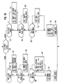
- Fig. 6a there is shown a simplified block diagram of a subroutine for adjusting the value of the slope at LRL.
- the pacemaker checks its clock and determines whether it is nighttime If this condition is met, the pacemaker then determines the at 56 whether the pacing rate is at LRL. If yes, then the pacemaker determines the slope at LRL (57). This is done by incrementally changing the pacing interval, with respect to LRL, and observing the change in QT. If the slope at LRL (A) is different, the new slope is stored in memory (58).
- a simplified block diagram of a subroutine for checking the value of the slope characteristic at URL At block 60, it is determined whether the pacemaker has been operating at URL. If yes, A determination is carried out, as shown at block 62, of whether the QT interval is now less than the old stored QT interval for URL. Thus, for heart cycles after reaching URL, the pacer monitors additional changes in the sensor value, and determines if continued exercise has caused further change in the sensor value. If no, then the routine exits, there being no indication that an adjustment is desired.
- the new value of QT is stored; the slope at URL is recalculated to correspond to the lesser value of QT at URL.
- a determination is made at block 67 as to whether URL has been reached within the last 8 days (or other predetermined time). If yes, then the slope at URL is incremented at block 68, reflecting the fact that the patient has a history of more moderate daily activity, such that slope at URL should be incremented. The slope is incremented so that the pacing rate reaches URL corresponding to the more moderate exercise level of the patient.
- the slope data settings are initially automatically set to low values.
- the dynamic slope rises to its optimal form, but this may take several days to reach.
- a fast learning procedure can be implemented, which essentially eliminates the initial adaptation phase.
- the patient is then put through a second stage where there is an exercise measurement, e.g., the patient is caused to perform an exercise stress test.
- the pacemaker is driven to upper rate limit, and calculates the slope corresponding to the upper rate limit.
- the optimal dynamic slope is filled in for all values of pacing rate between LRL and URL.
- subsequent adaptation may well occur,but the fast learning capability quickly brings the pacemaker quickly to a substantially optimum slope characteristic.
- the pacemaker In determining when and under what circumstances the slope is to be adjusted at URL, the pacemaker is programmed with a setting referred to as upper rate approach threshold, or URth, which is a threshold change in QT that must be determined before the slope is automatically adjusted.
- URth upper rate approach threshold
- the curve value of slope B is changed by one unit (e.g., from 20 to 21)
- This difference of necessary sensor input QT input that is required to exactly correspond to changing the slope curve factor B one step (for a given LRL and URL) is designated the "gradual" URth.
- the URth there are three programmable settings for the URth, the "standard" setting being the same as for gradual, but having an extra 6 ms QT change added; and the fast threshold being gradual plus 12 ms.
- the standard URth setting being adopted, the change in QT due to exercise to cause a change in B of one, after the patient has reached URL, must be 6 ms more than would correspond to changing the curve factor B by one.
- the slope may be adjusted for a sensed change at URL by keeping B fixed, but changing the A value.
- the slope A at LRL is also adjustable to one of preferably three settings. It is to be recalled that at nighttime, the slope at LRL is measured, representing the change in QT found to correspond to an incremental change in pacing interval. This nighttime measured slope is designated A n .
- an onset setting O n is utilized for determining when the measured value of A n differs from the old programmed A value by a sufficient amount to justify a change in the A value.
- O n can be +2, O or -2, corresponding to gradual, standard, and fast settings respectively.
- the measured value of A n plus the onset value are added and compared to the present stored value A, the comparison indicating whether a new value of A should be determined by incrementing or decrementing A by one. For example, of A n is measured to be 15 and O n is +2, the combined value of 17 is compared to the stored value of A. If A had a value of 20, then the sensed 17 is less than 20, and a new value of A is found by decrementing A by one unit.
- the value of A n is obtained at nighttime (81).
- the value of A n is added to the O n setting, and compared to the present value of A (82). If the contained value is not greater than A, the program branches to block 84 and decrements A by one unit. If the combined value is greater, then the value of A is incremented by one unit at block 85.
- the pacemaker system of this invention takes into account the fact that slope settings have to be recalculated when other parameters are changed.
- the slope at the new LRL has to be recalculated.
- the URth setting is a function of the new LRL.
- the pacemaker utilizes a reference curve which is stored in its memory and which contains all of the parameters from which slope is determined, namely LRL; slope A at LRL; onset O n for determining changes in slope at LRL; URL; slope curve factor B (which determines slope at URL); and URL aproach (URth).
- This reference curve is updated only automatically by the programmer upon interrogation, and then only once a day or when it does not correspond with the actual curve, as happens in response to exercise. In general, the only exceptions to this rule are during the fast learn procedure, which also adjusts the reference curve, and when upon interrogation the pacemaker indicates that it has been initialized.
- the pacemaker contains two sets of data, referred to as "actual” and as “reference”.
- the actual curve parameters are A and B, and the actual settings are LRL; URL O n and URth.
- the reference data contains six pieces of data corresponding to these same parameters.
- the preferred embodiment of this invention also provides for operating the pacemaker in a "fixed curve" mode, whereby the slope is not adaptable as a function of determinations made at LRL or URL.
- the curve can be changed manually by external programming, to change the slope in a predetermined small range.
- the programmer limits the changes to two steps form the reference curve per day, i.e. either A or B can be changed, but no more than by two steps per day. After each day, the reference curve can again be adjusted upon interrogation by the programmer, but again only by two steps in each direction.
- Fig. 9 there is shown a block diagram indicating how the pacemaker of this invention sets limits on the user's ability to change the reference curve data each day.
- the pacer is in the auto slope mode. If yes, at 91 it is determined whether it is a new day i.e., has there already been a change during this day? Thus if there has already been one programming episode during the day, the answer is no, and the program branches to block 92. At 92 it is determined whether the actual curve corresponds to the reference curve, i.e. whether the actual curve could be derived from the reference settings of A and B. If the actual curve does so correspond, the program exits.
- the program branches to block 96 where again it is determined if it is a new day. If no, the program exits directly, thus preventing additional changes for that day. If it is a new day, the program branches to block 97 where the actual settings are set equal to standard, i.e. both onset and URth are set to zero steps. The program then continues to 98 where the actual curve is placed into the reference curve, and then to block 99 where the actual settings are placed into the reference settings, thus providing a change in the reference curve in accordance with the settings that have been determined by the operator.
- Fig. 10 there is shown a more detailed flow diagram for carrying out the changes during external programming. It is noted that a change in LRL or URL may have already been programmed.
- the program starts as indicated at block 110, where the operator makes a decision as to whether to be in the fixed or automatic mode of adjusting slope. If auto is chosen, this means that it is desired to be in auto slope adjustment when the programming is through, and the path to the right is taken.
- the programmer checks to see whether the old, or prior slope had been fixed. If yes, this means that the program must make changes in accordance with the desire to go from fixed to auto, and the program branches to block 114.
- the actual onset parameter is set equal to the reference onset parameter, i.e., whatever onset information is in reference storage is put into storage corresponding to the actual curve.
- a new value of QTth is derived from the reference data, and placed in "actual" storage. Thus, if LRL or URL had been changed, a new corresponding reference QTth is calculated, and this actual value is made equal to this new value.
- the program then branches to block 116. Note that if the pacemaker had already been in auto slope mode, the program would go directly from 112 to 116.
- the operator makes a determination as to whether a new onset is to be selected. If no, the program proceeds directly to block 120. However, if a new onset is desired, the program branches to 118, where the selected onset is programmed and put into storage as the actual onset. Proceeding then to block 120, a similar decision is made as to whether a new QTth is to be selected. If no, the program proceeds directly to block 124, but if yes, it proceeds to block 122. There the operator inputs the new desired QTth, which is stored as the actual QTth data.
- the actual curve derived from the reference curve is updated, and the updated reference curve, i.e., that A and B slope parameters are calculated from the reference curve to give the pacer the actual curve. Then, at 126, the pacemaker is put into auto mode and exits the routine.
- the program branches to the left and at 130 determines whether the pacemaker had previously been in the auto mode. If no, meaning that it was already in the fixed mode, the program proceeds directly to block 134. If yes, the program branches to block 132, where the actual onset is set equal to the standard onset value of zero, and the actual URth is likewise set equal to zero. At 134, it is determined whether a new onset parameter is to be selected for storage in the pacer. If no, the program goes directly to block 138, but if yes, it branches to 136. There the actual onset value is set equal to the reference onset value plus or minus a selected number of onset steps.
- onset parameter may be changed by as much as plus or minus two steps in any given day.
- the program proceeds to block 138.
- the reference URth is updated as a function of LRL and URL, and then the actual URth is changed to a value equal to the reference URth plus or minus a selected number of URth steps (again limited to two steps per day).
- the URth can be changed by external programming, to achieve a faster or slower approach at URL, but this change is limited to two steps (e.g., each step being 6 ms) in any day. Proceeding to block 142, the actual slope curve parameters A and B are derived from the reference curve, and then at block 144 the pacemaker is set into the fixed slope mode and the program exits.
- a flexible pacemaker system for automatically adjusting rate response as a function of sensing change in at least one sensor input, at least pacing rate (or interval).
- changes are made in response to measurements at LRL and URL, but automatic adaptation can also be effected in different ways within the scope of the invention.
- an activity signal is generated from an activity-type sensor, and the activity sensor is then combined with the QT signal to get a two-sensor input "QT".
- the combined signal provides a quicker response to the onset of exercise due to the exercise component, but the QT component reduces the effect of spurious activity signals.
- the algorithm is unchanged; only the input is different.
- the algorithm simply acts upon a modified QT signal which has additional information. Also, each new reference valuable, i.e. QT ref is determined.
- Atrial rate can be controlled as a function of measured AV interval, i.e., the interval between a delivered atrial stimulus signal and the resulting ventricular beat.
- FIG 11 there is shown a flow diagram of a program for adjusting and controlling atrial pacing rate as a function of measured AV interval.
- the program is initialized, and at 152 the atrial escape interval (T AEI ) is set equal to T rr which corresponds to the rate-response interval.
- a V stimulus has been delivered. If yes, meaning that the AV interval timed out without a spontaneous ventricular beat, the program branches to block 160 where a new rate response interval T rr′ is set equal to T rr plus an arbitrary increment indicated as 12.8 ms. At block 161, it is determined whether T rr′ is greater than the interval corresponding to LRL. If yes, the program branches to 163. If the last ventricular occurrence was a stimulus, the program simply exits. If the last ventricular event was sensed, AV ref (which corresponds to QT ref ) is adjusted by adding a drift factor at block 165.
- T rr is set equal to T rr′
- AV ref is set equal to prior AV ref plus a fixed increment indicated as delta at block 166.
- block 168 it is determined whether there have been 16 consecutive increments of AV ref ; if no , the program exits, but if yes, and the last ventricular occurrence was sensed, AV ref is adjusted by subtracting a drift factor.
- Block 156 it is determined whether AV is greater than or equal to AV ref . If yes, the program branches over to block 160, corresponding to decreasing rate. If no, the program branches to block 175, corresponding to a desired rate increase. At 175, T rr′ is set equal to T rr - 12.8 ms. Then, at block 176, it is determined whether upper rate limit has been reached. If yes, the program branches to block 178, where AV ref is adjusted by subtracting a drift factor. If rate has not reached URL, then at block 180 T rr is set to the new value and AV ref is decremented by the fixed amount delta. As indicated at block 181, if this has happened sixteen times, AV ref is adjusted by subtracting the drift factor at 183; otherwise the program exits.
Landscapes
- Health & Medical Sciences (AREA)
- Heart & Thoracic Surgery (AREA)
- Life Sciences & Earth Sciences (AREA)
- Cardiology (AREA)
- Engineering & Computer Science (AREA)
- Physiology (AREA)
- Biophysics (AREA)
- Biomedical Technology (AREA)
- Nuclear Medicine, Radiotherapy & Molecular Imaging (AREA)
- Radiology & Medical Imaging (AREA)
- Animal Behavior & Ethology (AREA)
- General Health & Medical Sciences (AREA)
- Public Health (AREA)
- Veterinary Medicine (AREA)
- Electrotherapy Devices (AREA)
Claims (20)
- Herzschrittmachersystem (30, 32) mit sich adaptierender Frequenz zum Schrittmachen bei einem Patienten, wobei das System einen Schrittmacher, der eine Generatoreinrichtung (42) zum Erzeugen von Schrittmacherimpulsen mit einer gesteuerten Frequenz aufweist, wobei den Schrittmacherfrequenzen jeweils ein Schrittmacherintervall zugeordnet ist, eine Einrichtung (30) zum Überwachen mindestens einer mit der erwünschten Herzfrequenz korrelierenden Patientenvariablen und eine Frequenz-Steuereinrichtung (37, 38) zum Steuern der Generatoreinrichtung zum Erzeugen der Schrittmacherimpulse mit einer Frequenz, die eine Funktion der mindestens einen überwachten Variablen ist, aufweist,
dadurch gekennzeichnet, daß
die Frequenz-Steuereinrichtung eine Feststellungseinrichtung (57, 62) zum Feststellen der tatsächlichen Korrelation der Schrittmacherfrequenz und der Patientenvariablen bei einer vorbestimmten Schrittmacherfrequenz unter tatsächlichen Patientenbedingungen und eine Einstelleinrichtung (38) zum automatischen Einstellen der Funktion aufweist, so daß die durch der Funktion definierte Korrelation der Schrittmacherfrequenz und der Patientenvariablen bei der vorbestimmten Schrittmacherfrequenz der tatsächlichen Korrelation adäquat entspricht und somit die vergangene Entwicklung des Patientenzustands repräsentiert. - Herzschrittmachersystem nach Anspruch 1, bei dem die Generatoreinrichtung Schrittmacherimpulse mit Frequenzen in einem von einer Frequenz-Untergrenze (LRL) und einer Frequenz-Obergrenze (URL) begrenzten Bereich erzeugt, wobei die Einstelleinrichtung die Funktion so einstellt, daß die Korrelation der Schrittmacherfrequenz und der Patientenvariablen bei mindestens zwei entsprechenden Schrittmacherfrequenzen die vergangene Entwicklung des Patientenzustands repräsentiert (Fig. 6a und 6b).
- Herzschrittmachersystem nach Anspruch 2, bei dem eine der entsprechenden Schrittmacherfrequenzen LRL ist (Fig. 6a).
- Herzschrittmachersystem nach Anspruch 2, bei dem eine der entsprechenden Schrittmacherfrequenzen URL ist (Fig. 6b).
- Herzschrittmachersystem nach Anspruch 1, bei dem die Korrelation der Schrittmacherfrequenz und der Patientenvariablen eine als Steigung definierte Variable ist und bei dem die Einstelleinrichtung gespeicherte Werte für Steigungen für vorbestimmte inkrementelle Schrittmacherintervalle enthält.
- Herzschrittmachersystem nach Anspruch 5, bei dem die Steigung nichtlinear ist.
- Herzschrittmachersystem nach Anspruch 2, mit einer Einrichtung zum Bestimmen des LRL-Steigungswerts, wenn es eine vorbestimmte Tageszeit (55) ist und der Schrittmacher bei LRL (56) in Betrieb ist.
- Herzschrittmachersystem nach Anspruch 4, bei dem die Einstelleinrichtung eine Einrichtung zum Einstellen des Steigungswerts bei URL, wenn URL erreicht wird (60, 62, 64), enthält.
- Herzschrittmachersystem nach Anspruch 4, bei dem die Einstelleinrichtung eine Einrichtung enthält, mit der mindestens einmal in einem bestimmten Zeitraum URL eingestellt werden kann (67, 68).
- Herzschrittmachersystem nach Anspruch 5, bei dem die Einstelleinrichtung eine Einrichtung zum ständigen Überwachen von Veränderungen der Patientenvariablen, nachdem die Schrittmacherfrequenz URL erreicht hat, und zum Einstellen der URL entsprechenden Steigung gemäß der ständig überwachten Veränderungen aufweist.
- Herzschrittmachersystem nach Anspruch 1, bei dem die Einstelleinrichtung eine Einrichtung zum Einstellen der Funktion, wenn die Schrittmacherfrequenz einer vorbestimmten Frequenz entspricht, aufweist.
- Herzschrittmachersystem nach Anspruch 2, wobei der Schrittmacher eine Einrichtung, die bei vorhandenen spontanen Herzschlägen das Übermitteln von Schrittmachersignalen verhindert, und eine Übersteuerungseinrichtung zum Übermitteln eines oder mehrerer Schrittmacherimpulse während eines Zeitraums, in dem spontane Herzschläge erfaßt werden, aufweist und die mindestens eine Patientenvariable bei vorhandenen spontanen Herzschlägen überwacht.
- Herzschrittmachersystem nach Anspruch 1, bei dem die Überwachungseinrichtung eine Einrichtung zum Bestimmen von QT-Intervallen des Patienten aufweist und bei dem die Frequenz-Steuereinrichtung eine Einrichtung zum Speichern von Steigungsdaten aufweist, die eine vorbestimmte Gruppe von Schrittmacherintervallen repräsentieren, die entsprechenden QT-Intervallen entsprechen.
- Herzschrittmachersystem nach Anspruch 13, bei dem die Einstelleinrichtung eine Einrichtung zum automatischen Bestimmen der inkrementellen Veränderung des SchrittmacherintervallS bezüglich der inkrementellen Veränderung von QT bei LRL und zum Verändern der Steigungsdaten aufweist, so daß diese den festgelegten inkrementellen Veränderungen entsprechen.
- Herzschrittmachersystem nach Anspruch 13, bei dem die Einstelleinrichtung eine URL-Einstelleinrichtung zum Einstellen der Steigungsdaten enthält, so daß diese Steigungsdaten immer dann eine verringerte Steigung bei URL darstellen, wenn nach einem Ansteigen der Schrittmacherfrequenz auf URL ein weiteres Verkürzen von QT bestimmt wird.
- Herzschrittmachersystem nach Anspruch 2, bei dem die Einstelleinrichtung eine Einrichtung zum Bestimmen, wann (a) die gesteuerte Frequenz bei URL ist und wann (b) die mindestens eine Variable eine höhere Frequenz als URL anzeigt, und eine Einrichtung zum Einstellen der Steigung der Funktion bei URL, wenn die Bedingungen (a) und (b) festgestellt werden, aufweist.
- Herzschrittmachersystem nach Anspruch 1, bei dem die Generatoreinrichtung Schrittmacherimpulse mit Frequenzen innerhalb eines von einer Frequenz-Untergrenze (LRL) und einer Frequenz-Obergrenze (URL) begrenzten Bereichs erzeugt und bei dem die Einstelleinrichtung eine Einrichtung aufweist, die einen Wert für die Veränderung des Schrittmacherintervalls in bezug zum Intervall der Patientenvariablen bei LRL bestimmt und die Funktion bei LRL in Übereinstimmung mit der bestimmten Veränderung nachstellt.
- Herzschrittmacher nach Anspruch 1, bei dem die Generatoreinrichtung Schrittmacherimpulse mit Frequenzen innerhalb eines von einer Frequenz-Untergrenze (LRL) und einer Frequenz-Obergrenze (URL) begrenzten Bereichs erzeugt und bei dem die Einstelleinrichtung eine Einrichtung aufweist, die einen Wert für die Veränderung des Schrittmacherintervalls in bezug zum Intervall der Patientenvariablen bei URL bestimmt und die Funktion bei LRL in Übereinstimmung mit der bestimmten Veränderung nachstellt.
- Herzschrittmacher nach Anspruch 1, weiter durch eine Bestimmungseinrichtung gekennzeichnet, die weiter einen Wert für die Veränderung der Patientenvariablen in bezug auf das Schrittmacherintervall bei der mindestens einen Schrittmacherfrequenz bestimmt und bei dem die Einstelleinrichtung die Funktion bei der mindestens einen Schrittmacherfrequenz in Übereinstimmung mit dem bestimmten Wert nachstellt.
- Herzschrittmacher nach Anspruch 19, bei dem der Wert das Verhältnis der Veränderung der Patientenvariablen zu der Veränderung der Schrittmacherfrequenz (Steigung) ist.
Applications Claiming Priority (2)
| Application Number | Priority Date | Filing Date | Title |
|---|---|---|---|
| US07/252,643 US4972834A (en) | 1988-09-30 | 1988-09-30 | Pacemaker with improved dynamic rate responsiveness |
| US252643 | 1988-09-30 |
Publications (3)
| Publication Number | Publication Date |
|---|---|
| EP0361517A2 EP0361517A2 (de) | 1990-04-04 |
| EP0361517A3 EP0361517A3 (de) | 1992-01-29 |
| EP0361517B1 true EP0361517B1 (de) | 1995-11-29 |
Family
ID=22956915
Family Applications (1)
| Application Number | Title | Priority Date | Filing Date |
|---|---|---|---|
| EP89118071A Expired - Lifetime EP0361517B1 (de) | 1988-09-30 | 1989-09-29 | Herzschrittmacher mit adaptiver Schrittfrequenz |
Country Status (3)
| Country | Link |
|---|---|
| US (1) | US4972834A (de) |
| EP (1) | EP0361517B1 (de) |
| DE (1) | DE68924951T2 (de) |
Families Citing this family (66)
| Publication number | Priority date | Publication date | Assignee | Title |
|---|---|---|---|---|
| US5074302A (en) * | 1989-01-25 | 1991-12-24 | Siemens-Pacesetter, Inc. | Self-adjusting rate-responsive pacemaker and method thereof |
| EP0414928B2 (de) * | 1989-08-28 | 2003-01-29 | St. Jude Medical AB | Medizinisches Gerät zur Stimulation eines physiologischen Vorganges eines Lebewesens mit sich selbsttätig an die körperliche Aktivität des Lebewesens anpassender Stimulationsintensiät |
| US5154170A (en) * | 1990-08-14 | 1992-10-13 | Medtronic, Inc. | Optimization for rate responsive cardiac pacemaker |
| US5065759A (en) * | 1990-08-30 | 1991-11-19 | Vitatron Medical B.V. | Pacemaker with optimized rate responsiveness and method of rate control |
| US5144950A (en) * | 1990-08-30 | 1992-09-08 | Vitatron Medical B.V. | Rate controlled pacemaker system using ar interval for rate control |
| US5119813A (en) * | 1990-11-05 | 1992-06-09 | Leonard Bloom | Mixed venous oxygen saturation responsive system for and method of treating a malfunctioning heart |
| FR2671012B1 (fr) * | 1990-12-27 | 1993-03-19 | Ela Medical Sa | Procede de controle d'un stimulateur cardiaque. |
| FR2671013B1 (fr) * | 1990-12-27 | 1996-09-13 | Ela Medical Sa | Stimulateur cardiaque a frequence de stimulation asservie. |
| US5179947A (en) * | 1991-01-15 | 1993-01-19 | Cardiac Pacemakers, Inc. | Acceleration-sensitive cardiac pacemaker and method of operation |
| US5842997A (en) * | 1991-02-20 | 1998-12-01 | Georgetown University | Non-invasive, dynamic tracking of cardiac vulnerability by simultaneous analysis of heart rate variability and T-wave alternans |
| US5437285A (en) * | 1991-02-20 | 1995-08-01 | Georgetown University | Method and apparatus for prediction of sudden cardiac death by simultaneous assessment of autonomic function and cardiac electrical stability |
| SE9102376D0 (sv) * | 1991-08-16 | 1991-08-16 | Siemens Elema Ab | Implanterbar medicinsk apparat |
| US5247930A (en) * | 1992-02-04 | 1993-09-28 | Vitatron Medical, B.V. | Dual chamber pacing system with dynamic physiological tracking and method of timing delivered stimulus for optimized synchronous pacing |
| US5284491A (en) * | 1992-02-27 | 1994-02-08 | Medtronic, Inc. | Cardiac pacemaker with hysteresis behavior |
| US5423867A (en) * | 1992-03-02 | 1995-06-13 | Pacesetter, Inc. | Rate-responsive pacemaker having automatic sensor threshold with programmable offset |
| US5330513A (en) * | 1992-05-01 | 1994-07-19 | Medtronic, Inc. | Diagnostic function data storage and telemetry out for rate responsive cardiac pacemaker |
| US5330511A (en) * | 1993-01-19 | 1994-07-19 | Vitatron Medical B.V. | Dual chamber pacemaker with automatically optimized AV delay |
| US5562711A (en) * | 1994-11-30 | 1996-10-08 | Medtronic, Inc. | Method and apparatus for rate-responsive cardiac pacing |
| US5713930A (en) * | 1996-11-06 | 1998-02-03 | Vitatron Medical, B.V. | Dual chamber pacing system and method with control of AV interval |
| US5792195A (en) * | 1996-12-16 | 1998-08-11 | Cardiac Pacemakers, Inc. | Acceleration sensed safe upper rate envelope for calculating the hemodynamic upper rate limit for a rate adaptive cardiac rhythm management device |
| US5861011A (en) * | 1997-02-14 | 1999-01-19 | Vitatron Medical, B.V. | Pacemaker with automatic lower rate limit drop |
| DE19747820A1 (de) * | 1997-10-23 | 1999-04-29 | Biotronik Mess & Therapieg | Ratenadaptiver Herzschrittmacher |
| US6129744A (en) | 1997-12-04 | 2000-10-10 | Vitatron Medical, B.V. | Cardiac treatment system and method for sensing and responding to heart failure |
| DE19804843A1 (de) * | 1998-01-29 | 1999-08-05 | Biotronik Mess & Therapieg | Selbstkalibrierender ratenadaptiver Herzschrittmacher |
| US5978711A (en) * | 1998-02-23 | 1999-11-02 | Vivatron Medical, B.V. | Pacemaker system with improved learning capability for adapting rate response function |
| US6161041A (en) * | 1998-10-26 | 2000-12-12 | Vitatron Medical B. V. | Pacemaker system with diurnal pattern controlled overdrive for prevention of tachycardia |
| US7062325B1 (en) | 1999-05-21 | 2006-06-13 | Cardiac Pacemakers Inc | Method and apparatus for treating irregular ventricular contractions such as during atrial arrhythmia |
| US7212860B2 (en) | 1999-05-21 | 2007-05-01 | Cardiac Pacemakers, Inc. | Apparatus and method for pacing mode switching during atrial tachyarrhythmias |
| US7181278B2 (en) | 1999-05-21 | 2007-02-20 | Cardiac Pacemakers, Inc. | Apparatus and method for ventricular rate regularization |
| US8064997B2 (en) | 1999-05-21 | 2011-11-22 | Cardiac Pacemakers, Inc. | Method and apparatus for treating irregular ventricular contractions such as during atrial arrhythmia |
| US6501988B2 (en) * | 2000-12-26 | 2002-12-31 | Cardiac Pacemakers Inc. | Apparatus and method for ventricular rate regularization with biventricular sensing |
| US7142918B2 (en) * | 2000-12-26 | 2006-11-28 | Cardiac Pacemakers, Inc. | Apparatus and method for pacing mode switching during atrial tachyarrhythmias |
| US7239914B2 (en) * | 2000-05-13 | 2007-07-03 | Cardiac Pacemakers, Inc. | Rate smoothing control |
| US6501987B1 (en) | 2000-05-26 | 2002-12-31 | Cardiac Pacemakers, Inc. | Rate smoothing control |
| US7039461B1 (en) | 2000-05-13 | 2006-05-02 | Cardiac Pacemakers, Inc. | Cardiac pacing system for prevention of ventricular fibrillation and ventricular tachycardia episode |
| US8512220B2 (en) | 2000-05-26 | 2013-08-20 | Cardiac Pacemakers, Inc. | Rate smoothing control |
| US6424865B1 (en) | 2000-07-13 | 2002-07-23 | Cardiac Pacemakers, Inc. | Ventricular conduction delay trending system and method |
| US6512951B1 (en) | 2000-09-14 | 2003-01-28 | Cardiac Pacemakers, Inc. | Delivery of atrial defibrillation shock based on estimated QT interval |
| US6829504B1 (en) * | 2000-09-14 | 2004-12-07 | Cardiac Pacemakers, Inc. | System and method for preventing recurrence of atrial tachyarrhythmia |
| US6957100B2 (en) * | 2000-12-26 | 2005-10-18 | Cardiac Pacemakers, Inc. | Method and system for display of cardiac event intervals in a resynchronization pacemaker |
| US20020087198A1 (en) * | 2000-12-29 | 2002-07-04 | Kramer Andrew P. | Apparatus and method for ventricular rate regularization |
| US6804555B2 (en) | 2001-06-29 | 2004-10-12 | Medtronic, Inc. | Multi-site ventricular pacing system measuring QRS duration |
| US6668194B2 (en) | 2001-07-16 | 2003-12-23 | Medtronic, Inc. | Method and apparatus for monitoring conduction times in a bi-chamber pacing system |
| US6836682B2 (en) | 2001-11-16 | 2004-12-28 | Medtronic, Inc. | Rate responsive pacing system with QT sensor based on intrinsic QT data |
| US6721599B2 (en) | 2001-11-16 | 2004-04-13 | Medtronic, Inc. | Pacemaker with sudden rate drop detection based on QT variations |
| US6671549B2 (en) * | 2001-11-16 | 2003-12-30 | Medtronic, Inc. | Pacemaker utilizing QT dynamics to diagnose heart failure |
| US7386346B2 (en) * | 2002-04-22 | 2008-06-10 | Medtronic, Inc. | Controlled and modulated high power racing combined with intracardiac pressure monitoring feedback system utilizing the chronicle implantable hemodynamic monitoring (IHM) and calculated EPAD |
| US7844332B2 (en) | 2002-10-18 | 2010-11-30 | Cardiac Pacemakers, Inc. | Atrioventricular delay adjustment enhancing ventricular tachyarrhythmia detection |
| US7189204B2 (en) * | 2002-12-04 | 2007-03-13 | Cardiac Pacemakers, Inc. | Sleep detection using an adjustable threshold |
| US7363078B2 (en) * | 2003-04-24 | 2008-04-22 | Medtronic, Inc. | Intracardiac polarization signal stabilization |
| US7239915B2 (en) | 2003-12-16 | 2007-07-03 | Medtronic, Inc. | Hemodynamic optimization system for biventricular implants |
| US7203540B2 (en) | 2003-12-22 | 2007-04-10 | Cardiac Pacemakers, Inc. | Method and system for setting cardiac resynchronization therapy parameters |
| US7123960B2 (en) | 2003-12-22 | 2006-10-17 | Cardiac Pacemakers, Inc. | Method and system for delivering cardiac resynchronization therapy with variable atrio-ventricular delay |
| US8024050B2 (en) | 2003-12-24 | 2011-09-20 | Cardiac Pacemakers, Inc. | Lead for stimulating the baroreceptors in the pulmonary artery |
| US7162294B2 (en) | 2004-04-15 | 2007-01-09 | Ge Medical Systems Information Technologies, Inc. | System and method for correlating sleep apnea and sudden cardiac death |
| US20050234353A1 (en) * | 2004-04-15 | 2005-10-20 | Ge Medical Systems Information Technologies, Inc. | Method and apparatus for analysis of non-invasive cardiac parameters |
| US7415304B2 (en) * | 2004-04-15 | 2008-08-19 | Ge Medical Systems Information Technologies, Inc. | System and method for correlating implant and non-implant data |
| US7072709B2 (en) * | 2004-04-15 | 2006-07-04 | Ge Medical Information Technologies, Inc. | Method and apparatus for determining alternans data of an ECG signal |
| US7187966B2 (en) * | 2004-04-15 | 2007-03-06 | Ge Medical Systems Information Technologies, Inc. | Method and apparatus for displaying alternans data |
| US7509159B2 (en) * | 2004-04-15 | 2009-03-24 | Ge Medical Systems Information Technologies, Inc. | Method and apparatus for detecting cardiac repolarization abnormality |
| US7272435B2 (en) * | 2004-04-15 | 2007-09-18 | Ge Medical Information Technologies, Inc. | System and method for sudden cardiac death prediction |
| US20070191904A1 (en) * | 2006-02-14 | 2007-08-16 | Imad Libbus | Expandable stimulation electrode with integrated pressure sensor and methods related thereto |
| WO2009075749A1 (en) * | 2007-12-11 | 2009-06-18 | Cardiac Pacemakers, Inc. | Lv unipolar sensing or pacing vector |
| JP5438687B2 (ja) | 2007-12-13 | 2014-03-12 | カーディアック ペースメイカーズ, インコーポレイテッド | 単極検知ベクトルを提供するシステム |
| US8868178B2 (en) | 2012-12-11 | 2014-10-21 | Galvani, Ltd. | Arrhythmia electrotherapy device and method with provisions for mitigating patient discomfort |
| EP4514457A2 (de) * | 2022-04-29 | 2025-03-05 | Medtronic, Inc. | Bestimmung der unteren stimulationsfrequenzgrenze |
Family Cites Families (12)
| Publication number | Priority date | Publication date | Assignee | Title |
|---|---|---|---|---|
| US4228803A (en) * | 1978-06-23 | 1980-10-21 | Credit Du Nord International N.V. | Physiologically adaptive cardiac pacemaker |
| US4305396A (en) * | 1979-04-16 | 1981-12-15 | Vitatron Medical B.V. | Rate adaptive pacemaker and method of cardiac pacing |
| US4313442A (en) * | 1980-07-21 | 1982-02-02 | Cardiac Pacemakers, Inc. | Atrial rate sensitive cardiac pacer apparatus |
| US4493325A (en) * | 1982-05-03 | 1985-01-15 | Medtronic, Inc. | Tachyarrhythmia pacer |
| US4527568A (en) * | 1983-12-27 | 1985-07-09 | Vitafin N.V. | Dual chamber pacer with alternative rate adaptive means and method |
| US4644954A (en) * | 1984-01-10 | 1987-02-24 | Vitafin N.V. | Rate adaptive pacemaker apparatus and method |
| DE3419439C1 (de) * | 1984-05-24 | 1985-11-21 | Eckhard Dr. 8000 München Alt | Belastungsabhaengig frequenzvariabler Herzschrittmacher |
| DE3422913A1 (de) * | 1984-06-20 | 1986-01-02 | Siemens AG, 1000 Berlin und 8000 München | Regelschaltung zur anpassung der stimulationsfrequenz eines herzschrittmachers an die belastung eines patienten |
| US4566456A (en) * | 1984-10-18 | 1986-01-28 | Cordis Corporation | Apparatus and method for adjusting heart/pacer rate relative to right ventricular systolic pressure to obtain a required cardiac output |
| US4686988A (en) * | 1984-10-19 | 1987-08-18 | Sholder Jason A | Pacemaker system and method for measuring and monitoring cardiac activity and for determining and maintaining capture |
| US4716887A (en) * | 1985-04-11 | 1988-01-05 | Telectronics N.V. | Apparatus and method for adjusting heart/pacer rate relative to cardiac pCO2 to obtain a required cardiac output |
| US4803987A (en) * | 1986-06-11 | 1989-02-14 | Intermedics, Inc. | Temperature responsive controller for cardiac pacer |
-
1988
- 1988-09-30 US US07/252,643 patent/US4972834A/en not_active Expired - Lifetime
-
1989
- 1989-09-29 DE DE68924951T patent/DE68924951T2/de not_active Expired - Fee Related
- 1989-09-29 EP EP89118071A patent/EP0361517B1/de not_active Expired - Lifetime
Also Published As
| Publication number | Publication date |
|---|---|
| DE68924951D1 (de) | 1996-01-11 |
| EP0361517A2 (de) | 1990-04-04 |
| DE68924951T2 (de) | 1996-04-18 |
| US4972834A (en) | 1990-11-27 |
| EP0361517A3 (de) | 1992-01-29 |
Similar Documents
| Publication | Publication Date | Title |
|---|---|---|
| US4972834A (en) | Pacemaker with improved dynamic rate responsiveness | |
| US5144950A (en) | Rate controlled pacemaker system using ar interval for rate control | |
| US5065759A (en) | Pacemaker with optimized rate responsiveness and method of rate control | |
| US4856524A (en) | A-V responsive rate adaptive pacemaker | |
| US5330511A (en) | Dual chamber pacemaker with automatically optimized AV delay | |
| EP0543939B2 (de) | Optimierung für einen taktempfindlichen herzschrittmacher | |
| US5226413A (en) | Rate responsive pacemaker and method for automatically initializing the same | |
| EP0431083B1 (de) | Herzschrittmacher mit selbsttätiger einstellung der taktantwort | |
| US4941471A (en) | Rate stabilization pacemaker | |
| US5824019A (en) | Pacing system with physiologically timed ventricular pacing | |
| US5040534A (en) | Microprocessor controlled rate-responsive pacemaker having automatic rate response threshold adjustment | |
| US5282839A (en) | Rate responsive cardiac pacemaker and method for providing an optimized pacing rate which varies with a patient's physiologic demand | |
| US5312452A (en) | Cardiac rhythm management device with automatic optimization of performance related pacing parameters | |
| US5158078A (en) | Rate responsive pacemaker and methods for optimizing its operation | |
| EP0324598B1 (de) | Schrittmacher mit anpassbarer Schlagzahl | |
| US4644954A (en) | Rate adaptive pacemaker apparatus and method | |
| US5978711A (en) | Pacemaker system with improved learning capability for adapting rate response function | |
| EP0148486B1 (de) | Sich an die Frequenz anpassendes Schrittmachergerät | |
| EP1051992B1 (de) | Frequenzadaptiver Schrittmacher mit verbessertem Frequenzwechsel | |
| US5792196A (en) | Rate-responsive pacemaker with automatic rate response factor selection | |
| EP0804940A2 (de) | Frequenzadaptiver Herzschrittmacher mit automatischer Auswahl des Faktors der Taktantwort |
Legal Events
| Date | Code | Title | Description |
|---|---|---|---|
| PUAI | Public reference made under article 153(3) epc to a published international application that has entered the european phase |
Free format text: ORIGINAL CODE: 0009012 |
|
| AK | Designated contracting states |
Kind code of ref document: A2 Designated state(s): DE FR GB NL |
|
| PUAL | Search report despatched |
Free format text: ORIGINAL CODE: 0009013 |
|
| AK | Designated contracting states |
Kind code of ref document: A3 Designated state(s): DE FR GB NL |
|
| 17P | Request for examination filed |
Effective date: 19920331 |
|
| 17Q | First examination report despatched |
Effective date: 19940316 |
|
| GRAA | (expected) grant |
Free format text: ORIGINAL CODE: 0009210 |
|
| AK | Designated contracting states |
Kind code of ref document: B1 Designated state(s): DE FR GB NL |
|
| REF | Corresponds to: |
Ref document number: 68924951 Country of ref document: DE Date of ref document: 19960111 |
|
| ET | Fr: translation filed | ||
| PLBQ | Unpublished change to opponent data |
Free format text: ORIGINAL CODE: EPIDOS OPPO |
|
| PLBI | Opposition filed |
Free format text: ORIGINAL CODE: 0009260 |
|
| PGFP | Annual fee paid to national office [announced via postgrant information from national office to epo] |
Ref country code: FR Payment date: 19960920 Year of fee payment: 8 |
|
| PGFP | Annual fee paid to national office [announced via postgrant information from national office to epo] |
Ref country code: GB Payment date: 19960923 Year of fee payment: 8 |
|
| PLBF | Reply of patent proprietor to notice(s) of opposition |
Free format text: ORIGINAL CODE: EPIDOS OBSO |
|
| PGFP | Annual fee paid to national office [announced via postgrant information from national office to epo] |
Ref country code: NL Payment date: 19960930 Year of fee payment: 8 |
|
| 26 | Opposition filed |
Opponent name: BIOTRONIK MESS- UND THERAPIEGERAETE GMBH & CO INGE Effective date: 19960826 |
|
| NLR1 | Nl: opposition has been filed with the epo |
Opponent name: BIOTRONIK MESS- UND THERAPIEGERAETE GMBH & CO INGE |
|
| PLBF | Reply of patent proprietor to notice(s) of opposition |
Free format text: ORIGINAL CODE: EPIDOS OBSO |
|
| PLBL | Opposition procedure terminated |
Free format text: ORIGINAL CODE: EPIDOS OPPC |
|
| PLBM | Termination of opposition procedure: date of legal effect published |
Free format text: ORIGINAL CODE: 0009276 |
|
| STAA | Information on the status of an ep patent application or granted ep patent |
Free format text: STATUS: OPPOSITION PROCEDURE CLOSED |
|
| PG25 | Lapsed in a contracting state [announced via postgrant information from national office to epo] |
Ref country code: GB Free format text: LAPSE BECAUSE OF NON-PAYMENT OF DUE FEES Effective date: 19970929 |
|
| PG25 | Lapsed in a contracting state [announced via postgrant information from national office to epo] |
Ref country code: FR Free format text: THE PATENT HAS BEEN ANNULLED BY A DECISION OF A NATIONAL AUTHORITY Effective date: 19970930 |
|
| 27C | Opposition proceedings terminated |
Effective date: 19970627 |
|
| NLR2 | Nl: decision of opposition | ||
| PG25 | Lapsed in a contracting state [announced via postgrant information from national office to epo] |
Ref country code: NL Free format text: LAPSE BECAUSE OF NON-PAYMENT OF DUE FEES Effective date: 19980401 |
|
| GBPC | Gb: european patent ceased through non-payment of renewal fee |
Effective date: 19970929 |
|
| NLV4 | Nl: lapsed or anulled due to non-payment of the annual fee |
Effective date: 19980401 |
|
| REG | Reference to a national code |
Ref country code: FR Ref legal event code: ST |
|
| PGFP | Annual fee paid to national office [announced via postgrant information from national office to epo] |
Ref country code: DE Payment date: 19981126 Year of fee payment: 10 |
|
| PG25 | Lapsed in a contracting state [announced via postgrant information from national office to epo] |
Ref country code: DE Free format text: LAPSE BECAUSE OF NON-PAYMENT OF DUE FEES Effective date: 20000701 |