EP0361599B1 - Satz zur Versorgung einer gemischverdichtenden Brennkraftmaschine während besonderer Betriebsphasen - Google Patents
Satz zur Versorgung einer gemischverdichtenden Brennkraftmaschine während besonderer Betriebsphasen Download PDFInfo
- Publication number
- EP0361599B1 EP0361599B1 EP89202377A EP89202377A EP0361599B1 EP 0361599 B1 EP0361599 B1 EP 0361599B1 EP 89202377 A EP89202377 A EP 89202377A EP 89202377 A EP89202377 A EP 89202377A EP 0361599 B1 EP0361599 B1 EP 0361599B1
- Authority
- EP
- European Patent Office
- Prior art keywords
- air intake
- jet
- carburetor
- section
- supply
- Prior art date
- Legal status (The legal status is an assumption and is not a legal conclusion. Google has not performed a legal analysis and makes no representation as to the accuracy of the status listed.)
- Expired - Lifetime
Links
- 239000000203 mixture Substances 0.000 claims description 18
- 239000000446 fuel Substances 0.000 claims description 17
- 238000002485 combustion reaction Methods 0.000 claims description 3
- 230000001133 acceleration Effects 0.000 claims description 2
- 238000011084 recovery Methods 0.000 description 8
- 230000009471 action Effects 0.000 description 5
- 230000000694 effects Effects 0.000 description 3
- 238000005507 spraying Methods 0.000 description 3
- 238000009834 vaporization Methods 0.000 description 3
- 230000008016 vaporization Effects 0.000 description 3
- 230000008901 benefit Effects 0.000 description 2
- 230000005587 bubbling Effects 0.000 description 2
- 238000004891 communication Methods 0.000 description 2
- 230000002349 favourable effect Effects 0.000 description 2
- 238000000034 method Methods 0.000 description 2
- 230000001737 promoting effect Effects 0.000 description 2
- 238000004140 cleaning Methods 0.000 description 1
- 238000010276 construction Methods 0.000 description 1
- 239000008240 homogeneous mixture Substances 0.000 description 1
- 238000012986 modification Methods 0.000 description 1
- 230000004048 modification Effects 0.000 description 1
- 238000010137 moulding (plastic) Methods 0.000 description 1
- 210000000056 organ Anatomy 0.000 description 1
- 230000008569 process Effects 0.000 description 1
- 239000007921 spray Substances 0.000 description 1
- 239000007858 starting material Substances 0.000 description 1
Images


Classifications
-
- F—MECHANICAL ENGINEERING; LIGHTING; HEATING; WEAPONS; BLASTING
- F02—COMBUSTION ENGINES; HOT-GAS OR COMBUSTION-PRODUCT ENGINE PLANTS
- F02M—SUPPLYING COMBUSTION ENGINES IN GENERAL WITH COMBUSTIBLE MIXTURES OR CONSTITUENTS THEREOF
- F02M1/00—Carburettors with means for facilitating engine's starting or its idling below operational temperatures
- F02M1/04—Carburettors with means for facilitating engine's starting or its idling below operational temperatures the means to facilitate starting or idling being auxiliary carburetting apparatus able to be put into, and out of, operation, e.g. having automatically-operated disc valves
-
- F—MECHANICAL ENGINEERING; LIGHTING; HEATING; WEAPONS; BLASTING
- F02—COMBUSTION ENGINES; HOT-GAS OR COMBUSTION-PRODUCT ENGINE PLANTS
- F02M—SUPPLYING COMBUSTION ENGINES IN GENERAL WITH COMBUSTIBLE MIXTURES OR CONSTITUENTS THEREOF
- F02M3/00—Idling devices for carburettors
- F02M3/08—Other details of idling devices
- F02M3/09—Valves responsive to engine conditions, e.g. manifold vacuum
-
- Y—GENERAL TAGGING OF NEW TECHNOLOGICAL DEVELOPMENTS; GENERAL TAGGING OF CROSS-SECTIONAL TECHNOLOGIES SPANNING OVER SEVERAL SECTIONS OF THE IPC; TECHNICAL SUBJECTS COVERED BY FORMER USPC CROSS-REFERENCE ART COLLECTIONS [XRACs] AND DIGESTS
- Y10—TECHNICAL SUBJECTS COVERED BY FORMER USPC
- Y10S—TECHNICAL SUBJECTS COVERED BY FORMER USPC CROSS-REFERENCE ART COLLECTIONS [XRACs] AND DIGESTS
- Y10S261/00—Gas and liquid contact apparatus
- Y10S261/19—Degassers
-
- Y—GENERAL TAGGING OF NEW TECHNOLOGICAL DEVELOPMENTS; GENERAL TAGGING OF CROSS-SECTIONAL TECHNOLOGIES SPANNING OVER SEVERAL SECTIONS OF THE IPC; TECHNICAL SUBJECTS COVERED BY FORMER USPC CROSS-REFERENCE ART COLLECTIONS [XRACs] AND DIGESTS
- Y10—TECHNICAL SUBJECTS COVERED BY FORMER USPC
- Y10S—TECHNICAL SUBJECTS COVERED BY FORMER USPC CROSS-REFERENCE ART COLLECTIONS [XRACs] AND DIGESTS
- Y10S261/00—Gas and liquid contact apparatus
- Y10S261/74—Valve actuation; electrical
Definitions
- the present invention relates to a group intended to debit the supply to a carburetion engine under particular operating conditions, such as operation at minimum, the starting period, operation as engine brake and / or recovery.
- one or more elementary carburetors each of which comprises a venturi tube diffuser, a shutter and a sprayer supplied by a constant level tank d 'petrol, are capable of delivering to a carburetion engine a mixture of petrol and air sufficiently homogeneous to ensure correct operation, with regular performance and consumption and with sufficiently complete combustion to avoid excessive pollution of the environment.
- the device for supplying at minimum operation consists, in general, of an opening which feeds gasoline into the suction pipe downstream of the shutter, and the gasoline thus supplied cannot be sprayed and spray enough before reaching the cylinders.
- the starter device can have a structure similar to that indicated for the power supply device at least, with similar drawbacks, or it can include a small additional special carburetor, which however represents a solution excessively complicated and expensive.
- the recovery pump when it is provided, requires complicated mechanical or pneumatic devices for its actuation, and it delivers petrol under a very reduced pressure and therefore under conditions which are not suitable for efficient spraying.
- document US-A-4,329,964 describes a carburetor having an auxiliary device intended to operate at least during the engine operating at minimum, and comprising a main air intake independent of the air intake of the carburetor, under the shape of a Venturi tube defining a restricted section and connected to the suction pipe of the engine at a point of this pipe located downstream of the carburetor shutter, and a supply sprayer for operation at minimum, comprising a clean air intake and opening into the restricted section of said main air intake.
- the object of the present invention is to provide a group intended to be added to an elementary carburetor (single or multiple) in order to debit the supply to the engine under particular operating conditions, in which the different functions must be coordinated with one another.
- '' in a suitable manner and which, even with a substantially simple structure, must assure the engine the supply of a homogeneous mixture in which the petrol is suitably proportioned, sprayed in an efficient manner and vaporized, so that, even in the particular operating conditions, the engine can operate with satisfactory performance and consumption, without giving place to excessive pollution of the atmosphere.
- a group to be added to a carburetor to debit the supply to a carburetion engine under particular operating conditions, namely operation at minimum, the starting period, operation as engine brake and / or recovery characterized mainly in that it comprises a main air intake of the group, independent of the air intake of the carburetor, in the form of a Venturi tube, defining a restricted section and suitable for being connected to the suction duct of an engine at a point in this duct situated downstream of the shutter of the carburetor; a sprayer suitable for supply during operation at minimum, comprising at least one own air intake and opening into the restricted section of said main air intake; a sprayer suitable for supply during the start-up period, comprising at least one own air intake and opening into said main air intake downstream from its restricted section; and two solenoid valves arranged to intercept, respectively and independently, said sprayers.
- a mixture of gasoline and air is formed in the main air intake, which is introduced into the main air intake, into the engine suction duct, downstream of the carburetor shutter. in turn is formed by aspirated air and by a mixture of air and petrol previously formed in the sprayers provided with their own air intakes.
- the petrol is subjected, before being conveyed to the suction pipe, to repeated mixing, and thus it can reach a high degree of spraying and vaporization.
- the solenoid valves make it possible to exclude from the activity the sprayer for minimum operation or / and the sprayer for supply during the start-up period, when their operation is not desired.
- the sprayer for the minimum operation and the sprayer for the supply during the start-up period comprise a vertical tube immersed in the constant-level tank of gasoline of the carburetor and provided with a nozzle. of gasoline, and this tube is subdivided by a dividing wall, over part of its height, to define a section communicating with the clean air intake of the sprayer.
- this tube is subdivided by a dividing wall, over part of its height, to define a section communicating with the clean air intake of the sprayer.
- said dividing wall provided in the vertical tube at least of the sprayer for feeding during the start-up period extends over a part substantial of its height, thus determining a relatively high capacity section which communicates with the clean air intake of the sprayer.
- At least one of the sprayers also has another own air intake, arranged so as to mix air with the mixture of air and gasoline already formed in the sprayer . This increases the number of blends to which the gasoline is subjected, further promoting its spraying and vaporization.
- the vertical tube of at least one of the sprayers is surrounded by a second vertical tube which plunges into the tank of the carburetor, which is closed below by a bottom provided with a calibrated hole, and which is open at the top.
- This second vertical tube determines, with the vertical tube of the sprayer, a gap in which a lower fuel level is established than that of the constant level tank, depending on the fuel flow delivered.
- said main air intake, the sprayers, their air intakes and the connections for the solenoid valves form a unitary constructive element, to which the necessary calibrated nozzles are applied and , if necessary, the second vertical tubes.
- FIG. 5 in this figure is shown schematically by way of example a carburetor which is substantially of the type described in European Patent No. 0.069.416.
- This carburetor comprises a body A which forms a tank V and which is provided with a cover B. In the tank V, by devices well known per se, which therefore are not described here, a constant level of gasoline is maintained .
- the carburetor is provided with a rotary shutter O controlled by means of a shaft S pivoted in a hub Q of the body A. Under the body A and the shutter O extends a manifold P ending in a flange F intended to be connected to the suction manifold (not shown) of an internal combustion engine.
- the body A of the carburetor forms a diffuser D in the form of a Venturi tube, with a restricted section R.
- a sprayer G connected to a supply tube T which plunges into the tank V.
- These latter parts are used for supplying the engine under normal operating conditions and they are therefore not interested in the present invention.
- the group according to the invention described below and designated by reference numerals, is mounted on the cover B of the carburetor, with certain parts (16, 32) which plunge into the tank V, and it communicates with a conduit C of the body A.
- This conduit C opens at its lower end in the manifold P without being influenced by the shutter O.
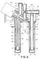
- FIG. 5 the group according to the invention is shown in a deployed view, corresponding to the section of FIG. 2.
- the group according to the invention comprises a main air intake substantially shaped like a Venturi tube with a restricted section 2 which divides the air intake into an exterior region 1, communicating with the atmosphere, and an interior region 3 which ends with a connector 4 intended to be put in communication, by the conduit C or in any other appropriate manner, with the suction conduit of the engine, downstream of the shutter of the carburetor.
- a main air intake substantially shaped like a Venturi tube with a restricted section 2 which divides the air intake into an exterior region 1, communicating with the atmosphere, and an interior region 3 which ends with a connector 4 intended to be put in communication, by the conduit C or in any other appropriate manner, with the suction conduit of the engine, downstream of the shutter of the carburetor.
- the device for operation at minimum speed comprises a duct 5 ( Figures 2 and 3) which opens at one of its ends in the restricted section 2 of the main air intake, and which at the opposite end communicates with the atmosphere by forming a primary air intake provided with a primary air nozzle 37.
- An opening 6 places the duct 5 in communication with a chamber 7 constituting the interior part of a connector 8 for an EM solenoid valve, per se well known and which therefore will not be described in detail.
- a first vertical tube 9 extends downward from the connector 8, and it is provided with a fuel nozzle 38 below. The tube 9 is subdivided into two sections 11 and 13, over a certain height from 'above, by a dividing wall 10.
- the internal section 11 opens in the chamber 7 by forming a valve seat 12 which can be closed by a valve head (not shown) of the solenoid valve EM.
- the external section 13 communicates with the atmosphere by forming a secondary air intake 14 provided with a secondary air jet 39.
- the vertical tube 9 has two flanges 15 to which is connected a second vertical tube 16 (FIG. 2) which forms with the first vertical tube 9 an interstice 20. This interstice communicates with the outside at its upper end by openings 17, while at its lower end the tube 16 is closed by a bottom 18 provided with a calibrated hole 19.
- the vertical tube 16 is intended to be immersed in the tank V at a constant level of gasoline from the carburetor, with its openings 17 arranged above the level L of gasoline in the tank.
- this device for feeding at minimum speed is as follows.
- the carburetor shutter is closed to force the engine to operate at minimum, in the suction duct C a relatively intense vacuum is established, which gives rise to the entry of air through the air intake main 1.
- An even more intense depression is then established in the restricted section 2, and it is transmitted to the duct 5 giving rise to the entry of primary air through the corresponding nozzle 37; moreover, through the opening 6 this depression is transmitted to the chamber 7.
- the solenoid valve EM is in the open position, in which it does not close the valve seat 12, this depression extends from the chamber 7 inside the vertical tube 9, and it gives rise to a suction of fuel through the fuel nozzle 38, as well as to a secondary air suction through the nozzle 39 correspondent.
- This secondary air descends in section 13 of the tube 9 until the termination of the dividing wall 10, then it rises in section 11 by bubbling through the gasoline sucked in by the gasoline nozzle 38, and thus mixes it. formed arrives, through the chamber 7 and the opening 6, in the duct 5, in which it subsequently mixes with the primary air sucked through the nozzle 37.
- the mixture thus formed is delivered in the restricted section 2 of the outlet main air 1, where it subsequently mixes with the air sucked through said main air intake, and then it is routed to the suction duct C.
- the sucked petrol is subjected to repeated operations of mixing with air, and therefore it is routed to the suction duct in a homogeneous state, very sprayed and vaporized, thus ensuring the best operating conditions of the engine at minimum speed.
- the mixture of gasoline in section 11 of the vertical tube 9 with the secondary air sucked through the corresponding nozzle 39 may be sufficient to deliver the mixture directly to the restricted section 2 of the main air intake 1, and in such cases the primary air intake with the nozzle 37 can be omitted.
- the device for starting comprises a duct 21 which opens at its internal end into the interior region 3 of the main air intake, and which at the opposite end opens into a chamber 23 ( Figures 2 and 4) constituting the internal part of a fitting 24 for an ES solenoid valve (per se well known and which therefore will not be described in detail), forming a valve seat 22 which can be closed by a valve head (not shown) of the 'ES solenoid valve.
- a primary air intake 25 provided with a primary air nozzle 40.
- a first vertical tube 26 extends downward from the connector 24, and it is provided below with a nozzle of gasoline 41. The tube 26 is subdivided into two sections 28 and 29, over a certain height from above, by a dividing wall 27.
- the internal section 28 opens into the chamber 23, while the external section 29 communicates with the atmosphere by forming a secondary air intake 30 provided with a secondary air jet 42.
- the connector 24 comprises a flange 31 to which a second vertical tube 32 is connected (FIG. 2) which forms with the first vertical tube 26 an interstice 36. This interstice communicates with the outside at its upper end by openings 33, while at its end lower the tube 32 is closed by a bottom 34 provided with a calibrated hole 35.
- the vertical tube 32 is intended to be immersed in the constant-level tank of gasoline of a carburetor, with its openings 33 arranged above the level L of petrol in the tank.
- this device for feeding during the start-up period is as follows.
- a relatively intense depression which gives rise to the entry of air through the main air intake 1.
- This depression is present in the interior region 3 of the air intake by the action of the restricted section 2, it is transmitted to the duct 21 and, if it is assumed that the solenoid valve ES is in the open position, in which it does not close the valve seat 22, this depression gives rise to the entry of primary air through the corresponding nozzle 40.
- this depression extends from the chamber 23 inside the vertical tube 26, and it gives rise to a suction of fuel through the fuel nozzle 41, as well as to a suction of secondary air through the corresponding nozzle 42.
- This secondary air descends in section 29 of the tube 26 until the termination of the dividing wall 27, then it rises in section 28 by bubbling through the gasoline sucked by the gasoline nozzle 41, and thus mixes it. formed arrives at the chamber 23, in which it subsequently mixes with the primary air sucked through the nozzle 40. The mixture thus formed arrives, via the conduit 21, at the interior region 3 of the main air intake 1, where it subsequently mixes with the air sucked through said main air intake, and then it is routed to the suction duct C.
- the gasoline sucked in is subjected to repeated operations of mixing with air, and therefore it is routed to the suction duct in a homogeneous state, very pulverized and vaporized, thus ensuring the best operating conditions of the engine during the starting period.
- the mixture of gasoline in section 28 of the vertical tube 26 with the secondary air sucked through the corresponding nozzle 42 may be sufficient to convey the mixture directly to the interior region 3 of the main air intake 1, and in such cases the primary air intake 25 with the nozzle 40 can be omitted.
- the dividing wall 27 extends almost to the lower end of the vertical tube 26, and therefore the section 29 of this tube has a considerable capacity.
- This section at the beginning of operation, that is to say before a vacuum is established in the suction manifold, is filled with petrol up to the level L of petrol in the tank. This represents a considerable reserve of fuel which can be drawn in substantially without any resistance when starting the engine, because it is not obliged to pass through any nozzle. This quantity of fuel therefore constitutes an additional supply which is supplied to the engine at the time of starting, and therefore it is the equivalent of the action of a recovery pump actuated automatically during starting.
- the ES solenoid valve During periods when choke activity is not required, the ES solenoid valve must be brought to the closed position, in which it completely prevents the activity of the starting device.
- This maneuver can be carried out by hand by means of a switch for supplying the solenoid valve ES, or else automatically by means of a small electric or electronic power station arranged to carry out this maneuver when the appropriate operating conditions arise, and particularly when the engine reaches a sufficiently high temperature.
- the starting device automatically operates as a recovery pump when it is actuated, this device can also be entrusted with the function of a recovery or acceleration pump after the start period has ended and , therefore, the ES solenoid valve closes the valve seat 22.
- said solenoid valve is momentarily moved to its open position so that the quantity of gasoline contained in the section 29 of the vertical tube 26 is sucked by the motor, as additional power, without encountering any resistance. Therefore, in cases where said solenoid valve is controlled by a small central unit, the latter can also be entrusted with the task of temporarily supplying the ES solenoid valve whenever the operating conditions of the motor suggest the intervention of a critique. Even in the absence of a central unit, this action can be entrusted to any known organ, usually used to actuate a recovery pump.
- this starting device is capable of supplying the engine with the necessary power without intervention of the device for operation at minimum speed. Consequently, under the conditions indicated, the solenoid valve EM can be worn in the closed condition, thus excluding the device operating at minimum speed, when the solenoid valve ES actuating the choke is opened.
- the two minimum and choke devices are left in operation simultaneously during start-up, which can be achieved by carrying the two solenoid valves EM and ES in the open position. A particularly increased power supply is then routed to the engine, making it easier to start under conditions of greatest difficulty.
- the EM solenoid valve first open, should be closed when the motor reaches a sufficient temperature, while when a higher temperature is reached, the procedure will be as usual. closing of the ES solenoid valve and simultaneously with the opening of the EM solenoid valve.
- the presence of the EM solenoid valve also allows very easy implementation of an operating condition in engine brake (so-called cut off). Indeed, it is sufficient to carry the EM solenoid valve in the closed position as long as the motor rotation speed is greater than a certain limit and when the vacuum in the suction duct, or any other appropriate parameter, indicates that the engine is operating as a brake. Also such a function can be entrusted with advantage to a small control center of solenoid valves.
- the group according to the invention is extremely compact and its various functions are coordinated between them, thus making it possible to obtain with a minimum bulk and without complicating the construction of the conditions much better operating performance than those usually obtained.
- the different parts of the group are very easy to access either for tuning up or for any cleaning operation.
- the group described is particularly suitable for being installed in a carburetor comprising several sprayers which are gradually discovered by a shutter, as in the example shown in FIG. 5, but it can also find application with a traditional carburetor comprising one or two bodies.
- the fuel sprinklers could be mounted in positions different from that shown; the tubes that have been defined as vertical could be vertical only in the process of approximation; the subdivision of the internal vertical tubes could be obtained by giving these tubes a U-shape with lower opening, instead of by introducing a dividing wall therein.
Landscapes
- Engineering & Computer Science (AREA)
- Chemical & Material Sciences (AREA)
- Combustion & Propulsion (AREA)
- Mechanical Engineering (AREA)
- General Engineering & Computer Science (AREA)
- Control Of The Air-Fuel Ratio Of Carburetors (AREA)
- Cooling, Air Intake And Gas Exhaust, And Fuel Tank Arrangements In Propulsion Units (AREA)
Claims (6)
Applications Claiming Priority (2)
| Application Number | Priority Date | Filing Date | Title |
|---|---|---|---|
| IT67875/88A IT1224457B (it) | 1988-09-30 | 1988-09-30 | Gruppo per l'alimentazione di un motore a carburazione in condizioni particolari di funzionamento |
| IT6787588 | 1988-09-30 |
Publications (3)
| Publication Number | Publication Date |
|---|---|
| EP0361599A2 EP0361599A2 (de) | 1990-04-04 |
| EP0361599A3 EP0361599A3 (en) | 1990-06-20 |
| EP0361599B1 true EP0361599B1 (de) | 1992-07-08 |
Family
ID=11306000
Family Applications (1)
| Application Number | Title | Priority Date | Filing Date |
|---|---|---|---|
| EP89202377A Expired - Lifetime EP0361599B1 (de) | 1988-09-30 | 1989-09-21 | Satz zur Versorgung einer gemischverdichtenden Brennkraftmaschine während besonderer Betriebsphasen |
Country Status (6)
| Country | Link |
|---|---|
| US (1) | US4960545A (de) |
| EP (1) | EP0361599B1 (de) |
| JP (1) | JPH02256861A (de) |
| DE (1) | DE68902030T2 (de) |
| ES (1) | ES2033081T3 (de) |
| IT (1) | IT1224457B (de) |
Families Citing this family (1)
| Publication number | Priority date | Publication date | Assignee | Title |
|---|---|---|---|---|
| US8333366B2 (en) * | 2010-03-08 | 2012-12-18 | Briggs & Stratton Corporation | Carburetor including one-piece fuel-metering insert |
Family Cites Families (16)
| Publication number | Priority date | Publication date | Assignee | Title |
|---|---|---|---|---|
| US2130666A (en) * | 1932-01-28 | 1938-09-20 | Carter Carburetor Corp | Fuel supply device for internal combustion engines |
| GB786625A (en) * | 1955-05-12 | 1957-11-20 | Weber Edoardo Spa | Thermostatically controlled starting device for carburetters of internal combustion engines |
| US3125084A (en) * | 1962-01-19 | 1964-03-17 | Fuel injection system | |
| DE1751802A1 (de) * | 1968-07-31 | 1971-05-06 | Bosch Gmbh Robert | Einspritzeinrichtung fuer Einspritz-Brennkraftmaschine |
| US3544083A (en) * | 1968-10-07 | 1970-12-01 | Gen Motors Corp | Carburetor |
| JPS50205B1 (de) * | 1969-10-22 | 1975-01-07 | ||
| US3878271A (en) * | 1972-05-17 | 1975-04-15 | Alfa Romeo Spa | Device for feeding the air-fuel mixture to an internal combustion engine during idling |
| US4124662A (en) * | 1974-05-02 | 1978-11-07 | Nissan Motor Company, Limited | Carburetor and method of operating same |
| JPS51136038A (en) * | 1975-05-17 | 1976-11-25 | Yamaha Motor Co Ltd | Internal combustion engine |
| US4108123A (en) * | 1976-07-30 | 1978-08-22 | Toyota Jidosha Kogyo Kabushiki Kaisha | Carburetor |
| US4329964A (en) * | 1978-03-17 | 1982-05-18 | Morris George Q | Liquid fuel carburetion system |
| US4285887A (en) * | 1979-01-29 | 1981-08-25 | Honda Giken Kogyo Kabushiki Kaisha | Carburetor |
| US4465461A (en) * | 1981-08-14 | 1984-08-14 | Schuetz Winfried | Dental-orthodontic device |
| JPS5867951U (ja) * | 1981-10-31 | 1983-05-09 | 愛三工業株式会社 | 気化器 |
| JPS5867950U (ja) * | 1981-11-02 | 1983-05-09 | 株式会社日立製作所 | 気化器の始動燃料供給装置 |
| JPS58192963A (ja) * | 1982-05-01 | 1983-11-10 | Sanshin Ind Co Ltd | 内燃機関の燃料制御装置 |
-
1988
- 1988-09-30 IT IT67875/88A patent/IT1224457B/it active
-
1989
- 1989-09-13 US US07/406,572 patent/US4960545A/en not_active Expired - Fee Related
- 1989-09-21 DE DE8989202377T patent/DE68902030T2/de not_active Expired - Fee Related
- 1989-09-21 EP EP89202377A patent/EP0361599B1/de not_active Expired - Lifetime
- 1989-09-21 ES ES198989202377T patent/ES2033081T3/es not_active Expired - Lifetime
- 1989-09-29 JP JP1255100A patent/JPH02256861A/ja active Pending
Also Published As
| Publication number | Publication date |
|---|---|
| IT8867875A0 (it) | 1988-09-30 |
| JPH02256861A (ja) | 1990-10-17 |
| EP0361599A3 (en) | 1990-06-20 |
| US4960545A (en) | 1990-10-02 |
| DE68902030T2 (de) | 1993-02-11 |
| DE68902030D1 (de) | 1992-08-13 |
| ES2033081T3 (es) | 1993-03-01 |
| IT1224457B (it) | 1990-10-04 |
| EP0361599A2 (de) | 1990-04-04 |
Similar Documents
| Publication | Publication Date | Title |
|---|---|---|
| FR2533186A1 (fr) | Decompresseur de dispositif de suralimentation a vide pour vehicules | |
| EP1947385A1 (de) | Vorrichtung zur Kraftstoffeinspritzung in eine Strömungsmaschine | |
| FR2726604A1 (fr) | Procede et dispositif de demarrage d'un moteur a combustion interne a l'aide d'un systeme d'alimentation par une source d'air | |
| FR2509379A1 (fr) | Carburateur pour moteurs a combustion interne, en particulier pour moteurs portables de tres faible puissance | |
| FR2767562A1 (fr) | Dispositif d'alimentation en carburant a partir d'un reservoir a pot accumulateur | |
| FR2516977A1 (fr) | Dispositif de propulsion marine comportant un dispositif mecanique a commande par pression de carburant pour l'amenee d'un melange carburant/huile | |
| FR2567579A1 (fr) | Appareil de pompage de combustible pour moteur a allumage par compression | |
| EP0361599A2 (de) | Satz zur Versorgung einer gemischverdichtenden Brennkraftmaschine während besonderer Betriebsphasen | |
| FR2501293A1 (fr) | Procede d'alimentation en melange air-essence d'un moteur a combustion interne et carburateur pour sa mise en oeuvre | |
| FR2580190A1 (fr) | Filtre a carburant et circuit d'alimentation en carburant equipe de ce filtre | |
| EP0323368B1 (de) | Vorrichtung zur pneumatischen Kraftstoffeinspritzung | |
| FR2772430A1 (fr) | Injecteur de carburant pour un moteur a combustion interne | |
| EP0361600B1 (de) | Zerstäubungsdüse für Vergaser einer gemischverdichtenden Brennkraftmaschine | |
| FR2773593A1 (fr) | Systeme d'injection de carburant pour moteurs a combustion interne | |
| FR2462567A1 (fr) | Carburateur a pression constante | |
| FR2685382A1 (fr) | Procede et dispositif pour l'introduction de gaz additionnels dans un moteur a combustion interne. | |
| FR2499159A1 (fr) | Dispositif d'admission de melange air-carburant pour moteur a combustion interne | |
| EP0218515B1 (de) | Vergaser für Brennkraftmaschine | |
| FR2487009A1 (fr) | Moteur a combustion interne equipe d'un circuit secondaire d'admission | |
| FR2638493A1 (fr) | Soupape de dosage et d'atomisation d'un systeme d'injection de moteur a combustion interne, avec un diviseur de debit de type ameliore | |
| FR2576976A1 (fr) | Dispositif d'atomisation de carburant par choc pour moteur a combustion interne | |
| BE534613A (de) | ||
| BE402055A (de) | ||
| BE432203A (de) | ||
| BE370573A (de) |
Legal Events
| Date | Code | Title | Description |
|---|---|---|---|
| PUAI | Public reference made under article 153(3) epc to a published international application that has entered the european phase |
Free format text: ORIGINAL CODE: 0009012 |
|
| AK | Designated contracting states |
Kind code of ref document: A2 Designated state(s): DE ES FR GB |
|
| PUAL | Search report despatched |
Free format text: ORIGINAL CODE: 0009013 |
|
| AK | Designated contracting states |
Kind code of ref document: A3 Designated state(s): DE ES FR GB |
|
| 17P | Request for examination filed |
Effective date: 19901210 |
|
| 17Q | First examination report despatched |
Effective date: 19910411 |
|
| GRAA | (expected) grant |
Free format text: ORIGINAL CODE: 0009210 |
|
| AK | Designated contracting states |
Kind code of ref document: B1 Designated state(s): DE ES FR GB |
|
| REF | Corresponds to: |
Ref document number: 68902030 Country of ref document: DE Date of ref document: 19920813 |
|
| GBT | Gb: translation of ep patent filed (gb section 77(6)(a)/1977) | ||
| REG | Reference to a national code |
Ref country code: ES Ref legal event code: FG2A Ref document number: 2033081 Country of ref document: ES Kind code of ref document: T3 |
|
| PLBE | No opposition filed within time limit |
Free format text: ORIGINAL CODE: 0009261 |
|
| STAA | Information on the status of an ep patent application or granted ep patent |
Free format text: STATUS: NO OPPOSITION FILED WITHIN TIME LIMIT |
|
| 26N | No opposition filed | ||
| PGFP | Annual fee paid to national office [announced via postgrant information from national office to epo] |
Ref country code: GB Payment date: 19930915 Year of fee payment: 5 |
|
| PGFP | Annual fee paid to national office [announced via postgrant information from national office to epo] |
Ref country code: ES Payment date: 19930922 Year of fee payment: 5 |
|
| PGFP | Annual fee paid to national office [announced via postgrant information from national office to epo] |
Ref country code: FR Payment date: 19930929 Year of fee payment: 5 |
|
| PGFP | Annual fee paid to national office [announced via postgrant information from national office to epo] |
Ref country code: DE Payment date: 19931022 Year of fee payment: 5 |
|
| PG25 | Lapsed in a contracting state [announced via postgrant information from national office to epo] |
Ref country code: GB Effective date: 19940921 |
|
| PG25 | Lapsed in a contracting state [announced via postgrant information from national office to epo] |
Ref country code: ES Free format text: LAPSE BECAUSE OF THE APPLICANT RENOUNCES Effective date: 19940922 |
|
| GBPC | Gb: european patent ceased through non-payment of renewal fee |
Effective date: 19940921 |
|
| PG25 | Lapsed in a contracting state [announced via postgrant information from national office to epo] |
Ref country code: FR Effective date: 19950531 |
|
| PG25 | Lapsed in a contracting state [announced via postgrant information from national office to epo] |
Ref country code: DE Effective date: 19950601 |
|
| REG | Reference to a national code |
Ref country code: FR Ref legal event code: ST |
|
| REG | Reference to a national code |
Ref country code: ES Ref legal event code: FD2A Effective date: 19991007 |