EP0361604B1 - Eckverbindung für Abstandshalterahmen für Isolierglasscheiben und dafür verwendete Profile - Google Patents
Eckverbindung für Abstandshalterahmen für Isolierglasscheiben und dafür verwendete Profile Download PDFInfo
- Publication number
- EP0361604B1 EP0361604B1 EP89202399A EP89202399A EP0361604B1 EP 0361604 B1 EP0361604 B1 EP 0361604B1 EP 89202399 A EP89202399 A EP 89202399A EP 89202399 A EP89202399 A EP 89202399A EP 0361604 B1 EP0361604 B1 EP 0361604B1
- Authority
- EP
- European Patent Office
- Prior art keywords
- profiles
- corner
- profile
- walls
- arms
- Prior art date
- Legal status (The legal status is an assumption and is not a legal conclusion. Google has not performed a legal analysis and makes no representation as to the accuracy of the status listed.)
- Expired - Lifetime
Links
- 238000007789 sealing Methods 0.000 claims abstract description 26
- 239000010426 asphalt Substances 0.000 claims description 7
- 239000003292 glue Substances 0.000 claims description 3
- 229910052751 metal Inorganic materials 0.000 claims description 3
- 239000002184 metal Substances 0.000 claims description 3
- 239000004033 plastic Substances 0.000 claims description 3
- 239000007779 soft material Substances 0.000 claims description 3
- 230000003313 weakening effect Effects 0.000 claims description 2
- 238000003780 insertion Methods 0.000 description 8
- 230000037431 insertion Effects 0.000 description 8
- 239000000463 material Substances 0.000 description 5
- 239000011521 glass Substances 0.000 description 4
- ATJFFYVFTNAWJD-UHFFFAOYSA-N Tin Chemical compound [Sn] ATJFFYVFTNAWJD-UHFFFAOYSA-N 0.000 description 3
- 239000011133 lead Substances 0.000 description 3
- 239000011135 tin Substances 0.000 description 3
- 229910052782 aluminium Inorganic materials 0.000 description 2
- XAGFODPZIPBFFR-UHFFFAOYSA-N aluminium Chemical compound [Al] XAGFODPZIPBFFR-UHFFFAOYSA-N 0.000 description 2
- 239000002274 desiccant Substances 0.000 description 2
- 238000010792 warming Methods 0.000 description 2
- 239000004411 aluminium Substances 0.000 description 1
- 238000010276 construction Methods 0.000 description 1
- 238000009434 installation Methods 0.000 description 1
- 238000005259 measurement Methods 0.000 description 1
- 230000008018 melting Effects 0.000 description 1
- 238000002844 melting Methods 0.000 description 1
- 230000035699 permeability Effects 0.000 description 1
- 238000007790 scraping Methods 0.000 description 1
- 230000008719 thickening Effects 0.000 description 1
Images

Classifications
-
- E—FIXED CONSTRUCTIONS
- E06—DOORS, WINDOWS, SHUTTERS, OR ROLLER BLINDS IN GENERAL; LADDERS
- E06B—FIXED OR MOVABLE CLOSURES FOR OPENINGS IN BUILDINGS, VEHICLES, FENCES OR LIKE ENCLOSURES IN GENERAL, e.g. DOORS, WINDOWS, BLINDS, GATES
- E06B3/00—Window sashes, door leaves, or like elements for closing wall or like openings; Layout of fixed or moving closures, e.g. windows in wall or like openings; Features of rigidly-mounted outer frames relating to the mounting of wing frames
- E06B3/96—Corner joints or edge joints for windows, doors, or the like frames or wings
- E06B3/9616—Corner joints or edge joints for windows, doors, or the like frames or wings characterised by the sealing at the junction of the frame members
- E06B3/962—Mitre joints
-
- E—FIXED CONSTRUCTIONS
- E06—DOORS, WINDOWS, SHUTTERS, OR ROLLER BLINDS IN GENERAL; LADDERS
- E06B—FIXED OR MOVABLE CLOSURES FOR OPENINGS IN BUILDINGS, VEHICLES, FENCES OR LIKE ENCLOSURES IN GENERAL, e.g. DOORS, WINDOWS, BLINDS, GATES
- E06B3/00—Window sashes, door leaves, or like elements for closing wall or like openings; Layout of fixed or moving closures, e.g. windows in wall or like openings; Features of rigidly-mounted outer frames relating to the mounting of wing frames
- E06B3/66—Units comprising two or more parallel glass or like panes permanently secured together
- E06B3/663—Elements for spacing panes
- E06B3/667—Connectors therefor
-
- F—MECHANICAL ENGINEERING; LIGHTING; HEATING; WEAPONS; BLASTING
- F16—ENGINEERING ELEMENTS AND UNITS; GENERAL MEASURES FOR PRODUCING AND MAINTAINING EFFECTIVE FUNCTIONING OF MACHINES OR INSTALLATIONS; THERMAL INSULATION IN GENERAL
- F16B—DEVICES FOR FASTENING OR SECURING CONSTRUCTIONAL ELEMENTS OR MACHINE PARTS TOGETHER, e.g. NAILS, BOLTS, CIRCLIPS, CLAMPS, CLIPS OR WEDGES; JOINTS OR JOINTING
- F16B2200/00—Constructional details of connections not covered for in other groups of this subclass
- F16B2200/65—Miter joints
-
- F—MECHANICAL ENGINEERING; LIGHTING; HEATING; WEAPONS; BLASTING
- F16—ENGINEERING ELEMENTS AND UNITS; GENERAL MEASURES FOR PRODUCING AND MAINTAINING EFFECTIVE FUNCTIONING OF MACHINES OR INSTALLATIONS; THERMAL INSULATION IN GENERAL
- F16B—DEVICES FOR FASTENING OR SECURING CONSTRUCTIONAL ELEMENTS OR MACHINE PARTS TOGETHER, e.g. NAILS, BOLTS, CIRCLIPS, CLAMPS, CLIPS OR WEDGES; JOINTS OR JOINTING
- F16B2200/00—Constructional details of connections not covered for in other groups of this subclass
- F16B2200/67—Rigid angle couplings
-
- Y—GENERAL TAGGING OF NEW TECHNOLOGICAL DEVELOPMENTS; GENERAL TAGGING OF CROSS-SECTIONAL TECHNOLOGIES SPANNING OVER SEVERAL SECTIONS OF THE IPC; TECHNICAL SUBJECTS COVERED BY FORMER USPC CROSS-REFERENCE ART COLLECTIONS [XRACs] AND DIGESTS
- Y10—TECHNICAL SUBJECTS COVERED BY FORMER USPC
- Y10T—TECHNICAL SUBJECTS COVERED BY FORMER US CLASSIFICATION
- Y10T403/00—Joints and connections
- Y10T403/47—Molded joint
- Y10T403/472—Molded joint including mechanical interlock
-
- Y—GENERAL TAGGING OF NEW TECHNOLOGICAL DEVELOPMENTS; GENERAL TAGGING OF CROSS-SECTIONAL TECHNOLOGIES SPANNING OVER SEVERAL SECTIONS OF THE IPC; TECHNICAL SUBJECTS COVERED BY FORMER USPC CROSS-REFERENCE ART COLLECTIONS [XRACs] AND DIGESTS
- Y10—TECHNICAL SUBJECTS COVERED BY FORMER USPC
- Y10T—TECHNICAL SUBJECTS COVERED BY FORMER US CLASSIFICATION
- Y10T403/00—Joints and connections
- Y10T403/55—Member ends joined by inserted section
- Y10T403/555—Angle section
Definitions
- This invention relates to a corner connection for frames for double glazing, comprising two hollow frame profiles to be connected to each other, each profile having a first cavity and a second cavity; and a corner profile comprising a pair of arms, one arm being inserted into the first cavity of one frame profile and the other arm being inserted into the first cavity of the other frame profile.
- double glazing can principally be realized in two days namely, either by joining together two or more sheets of glass with the insertion of a frame, mostly in aluminium, or by installing one or more glass panels next to an existing mostly single glazing likewise with the insertion of a frame.
- such frames are formed by hollow profiles which are connected to each other at the extremities by corner profiles of which the arms are placed in the hollow profiles in order the obtain a connection at a suitable angle.
- connection Generally such a connection will form an angle of 90 degrees.
- a difficulty found in realizing such frames is that the necessary sealing at the corners often leaves something to be desired. According to DE-U-8402718 the corner profile does not provide for any sealing.
- the present invention has a corner connection as objective which can be realized in a very simple manner with maximum security regarding the seal of the corner connection.
- the corner profile comprises also a sealing wall between the arms, which after joining together the profiles, seals the second cavities of the frame profiles at the free ends thereof.
- a corner connection comprising a corner profile having between its arms a plate being inserted between the ends of two frame profiles to be connected is known from EP-A-255510.
- the frame profiles are not provided with cavities.
- the plate serves to protect the ends of the frame profiles and not to seal.
- the frame profiles are profiles of a window frame and not part of a frame for double glazing.
- the sealing wall of the corner profile will seal off the open extremity of the adjacent profiles to be joined to each other whereby, through possible additional warming of the corner connection, a seal is obtained because the material, that is generally provided on the side walls of such frame profiles, usually bitumen, fills the spaces around the aforementioned sealing wall between the adjacent profiles to be joined to each other.
- either the aforementioned sealing wall, or the aforementioned sealing wall and at least a part of the arms of the corner connection can be provided with a material such as mentioned above, namely tin, lead, bitumen, etc. in order to obtain a sealing of the corner connection thus already by the insertion of the arms of the corner profile in the cavities of the profiles to be joined to each other which is completed after complete insertion of the arms of the corner profile.
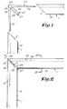
- each profile according to the invention consists of a closed cavity 3, on the one hand, and above this closed cavity 3 an open cavity 4, on the other hand.
- the closed cavity 3 shows a lower wall 5; two side walls 6, 7 and an upper wall 8 whereby this upper wall also forms lower wall of the open space 4 which is further completed by side walls, respectively 9 and 10 which as it were form an extension of the aforementioned walls 6 and 7 and flanges 11 and 12 which are provided with the walls 9 and 10 on the free extremities and which are directed towards each other and parallel with the aforementioned wall 8.
- the wall 5 extends out on the sides of the walls 6 and 7 and there forms ribs 14, 15.
- the walls 6-9 and 7-10 are each provided on their outer side with a quantity of bitumen or similar 16-17 which is provided with a covering strip 18-19, of which it is later the intention among others, after removing the strips 18 and 19, to make a sealing contact with the sheets of glass not shown in the drawings.
- connection of the profiles 1 according to the invention is obtained by means of a corner profile 20 that consists of arms, respectively 21, 22 which in this case are placed at an angle of 90 degrees and that, have a sealing wall 23 in the corner where these arms 21 and 22 come together which is placed at an angle of 45 degrees in relation to the aforementioned arms.
- the arms 21 and 22 are produced conically in order to simplify their insertion into the profile 1 whereby these arms, at the position where they meet each other, show a thickness which is equal or almost equal to the corresponding measurement of the open cavity 4 of the profile 1 in which the arms 21 and 22 are installed. These thickened places are indicated by 24, 25 in the drawings.
- the aforementioned sealing wall 23 in this case is so achieved that it shows two relatively thin parts, respectively 26 and 27, on its terminal edges which will act as stop for the cut off extremities 2 of the profiles 1, while the body 28 of the sealing wall 23 is produced thicker and, after installation of the profile 1 over the arms of the corner profile 20, fits into the closed cavity 3 of the profiles 1.
- the width of the corner element 20 is equal to the internal distance between the walls 9 and 10 of the cavity 4; the thickened parts 24 and 25 of the corner profile 20 are equal to the internal distance between the wall 8 and the flanges 11, 12; the parts 26 and 27 of the corner element 20 are placed between the adjacent walls 8, on the one hand, and 5, on the other hand, and finally the thickened part 28 of the sealing wall 23 is placed in the adjacent extremities of the closed cavity 3 of the profiles 1, in this manner not only an efficient connection is obtained between two profiles 1, but at the same time an efficient sealing of the extremities of these profiles 1.
- a seal can of course still be improved by at least providing the sealing wall 23 and possibly at least a part of the arms 21 and 22 of the corner profile 20 with a covering which can be formed by a soft metal, such as tin, lead or similar, a glue, a plastic, bitumen, or similar, through which not only an additional seal is obtained during the insertion of the arms 21 and 22 in the open cavities 4 of two profiles 1, but whereby this seal becomes maximally efficient when at the same time at least at the location of the corner connection, heat is applied to allow the aforementioned covering to fill all possible remaining spaces.
- a soft metal such as tin, lead or similar
- a glue, a plastic, bitumen, or similar through which not only an additional seal is obtained during the insertion of the arms 21 and 22 in the open cavities 4 of two profiles 1, but whereby this seal becomes maximally efficient when at the same time at least at the location of the corner connection, heat is applied to allow the aforementioned covering to fill all possible remaining spaces.
- sealing wall 23 shows a thickening 28. Indeed this sealing wall 23, as is schematically shown in figure 1 by means of dotted line 30, could show the same thickness over the whole length.
- weakenings may possibly be provided in the inner corners 31 and 32 between the walls 9-10 and the flanges 11-12 through which these lips 11 and 12 become more transformable, respectively adjustable.
- a corner profile 20 according to the invention also further allows that it is easily transformable through which the arms of this can be placed at almost any angle when frames would have to be formed of which the angles are different from 90 degrees.
- the groove formed between the flanges 11 and 12 of it, which allows access to the open profile 4 can be applied to connect such frames with an additional construction, either by sliding in fixing elements in such cavity 4 beforehand, or by installing already known fixing elements which can block after rotation in such cavity 4.
- implemented frames can be applied in glass walls and similar.
- corner profile 20, and/or the profiles 1 can be implemented in metal, for example aluminum, or in a suitable plastic, whereby in this last case, in order to limit the permeability in the open cavity 4, preferably an impermeable covering is provided against the wall 8.
Landscapes
- Engineering & Computer Science (AREA)
- Civil Engineering (AREA)
- Structural Engineering (AREA)
- Securing Of Glass Panes Or The Like (AREA)
- Residential Or Office Buildings (AREA)
- Wing Frames And Configurations (AREA)
- Joining Of Corner Units Of Frames Or Wings (AREA)
- Shielding Devices Or Components To Electric Or Magnetic Fields (AREA)
- Joining Of Building Structures In Genera (AREA)
- Mutual Connection Of Rods And Tubes (AREA)
Claims (11)
- Eckverbindung für Rahmen für Doppelverglasung , bestehend aus zwei Hohlrahmen-Profilen (1), die miteinander verbunden werden, wobei jedes Profil (1) einen ersten Hohlraum (4) und einen zweiten Hohlraum (3) besitzt, und einem Eckprofil (20), das aus zwei Armen (21 und 22) besteht, wobei ein Arm (21) in den ersten Hohlraum (4) des einen Rahmenprofils (1) und der andere Arm (21) in den ersten Hohlraum (4) des anderen Profils (1) eingesetzt wird, dadurch gekennzeichnet, daß das genannte Eckprofil (20) ebenso eine Dichtungsplatte (23) zwischen den Armen (21-22) besitzt, die nach Zusammensetzen der Profile (1) die zweiten Hohlräume (3) der Rahmenprofile (1) an ihrem freien Ende abdichtet.
- Eckverbindung entsprechend Anspruch 1, dadurch gekennzeichnet, daß jedes Profil (1) durch zwei prinzipielle Komponenten, d.h. den geschlossenen Hohlraum (3) und den offenen Hohlraum (4) darüber gebildet wird.
- Eckverbindung entsprechend Anspruch 2, dadurch gekennzeichnet, daß der geschlossene Hohlraum (3) aus zwei Seitenwänden (6-7), einem unteren Wand (5) und einem oberen Wand (8) besteht, wobei im unteren Wand einerseits kleine Öffnungen vorgesehen sind und wobei der offene Hohlraum (4) aus zwei Seitenwänden (9-10) besteht, die eine Fortsetzung der oben angeführten Seitenwänden (6-7) bilden, während der untere Wand des oben angeführten oberen Wandes (8) des Hohlraums (3) und die Flansche (11-12) andererseits einander gegenüberliegend auf den freien Endstücken der zuvor genannten Wänden (9-10) positioniert sind und parallel zum Wand (8) liegen.
- Eckverbindung entsprechend Anspruch 3, dadurch gekennzeichnet, daß der zuvor angeführte untere Wand (5) Rippen (14-15) aufweist, die die Wände (6-7) außen erweitern.
- Eckverbindung entsprechend Anspruch 3, dadurch gekennzeichnet, daß die Ecken (31-32) zwischen den Wänden (9-10) sowie den Flanschen (11-12) Schwächungen aufweisen.
- Eckverbindung entsprechend einem der vorangehenden Ansprüche, dadurch gekennzeichnet, daß die Seitenwände (6-9) sowie (7-10) der Rahmenprofile (1) jeweils mit einer Bitumenschicht (16-17) beschichtet sind.
- Eckverbindung entsprechend Anspruch 3, dadurch gekennzeichnet, daß die Arme (21-22) des Eckprofils (20) konisch zulaufen, wodurch an dem Punkt, an dem diese Arme (21-22) zusammenkommen, letztere eine Dicke (24-25) aufweisen, die dem Abstand zwischen dem oben angeführten Wand (8) und den Flanschen (11-12) des offenen Hohlraums der Profile (1) gleichen resp. fast entsprechen.
- Eckverbindung entsprechend Anspruch 3, dadurch gekennzeichnet, daß das Eckprofil (20) eine Breite aufweist, die dem Abstand zwischen den Wänden (6-9) und (7-10) gleicht oder fast gleicht.
- Eckverbindung entsprechend den Ansprüchen 1 bis 8, dadurch gekennzeichnet, daß die Dichtungsplatte (23) als Stopp für die Wände (8) und (5) der Profile (1) dient.
- Eckverbindung entsprechend Anspruch 9, dadurch gekennzeichnet, daß die Dichtungsplatte (23) zwei relativ dünne Teile (26) und (27) aufweist, die als Stopp für die Wände (8) und (5) der Profile (1) dienen, wobei zwischen diesen Komponenten (26-27) die Dichtungsplatte (23) dicker gefertigt wird und auf diese Weise nach Montage der Profile (1) auf den Armen (21-22) des Eckprofils (20) in die Hohlräume (3) der angrenzenden Profile (1) paßt.
- Eckverbindung entsprechend einem der vorangehenden Ansprüche, dadurch gekennzeichnet, daß vor einer Montage des Eckprofiles (20) in die Profile (1) zumindest die Dichtungsplatte (23) und möglicherweise zumindest ein Teil der Arme (21-22) des Eckprofils mit einem weichen Material, wie einem Weichmetall, Klebstoff, Kunststoff, Bitumen oder ähnlichem, beschichtet werden.
Priority Applications (1)
| Application Number | Priority Date | Filing Date | Title |
|---|---|---|---|
| AT89202399T ATE83035T1 (de) | 1988-09-28 | 1989-09-25 | Eckverbindung fuer abstandshalterahmen fuer isolierglasscheiben und dafuer verwendete profile. |
Applications Claiming Priority (2)
| Application Number | Priority Date | Filing Date | Title |
|---|---|---|---|
| BE8801104A BE1002510A6 (nl) | 1988-09-28 | 1988-09-28 | Hoekverbinding voor kaders voor dubbele beglazing en profielen hierbij aangewend. |
| BE8801104 | 1988-09-28 |
Publications (2)
| Publication Number | Publication Date |
|---|---|
| EP0361604A1 EP0361604A1 (de) | 1990-04-04 |
| EP0361604B1 true EP0361604B1 (de) | 1992-12-02 |
Family
ID=3883650
Family Applications (1)
| Application Number | Title | Priority Date | Filing Date |
|---|---|---|---|
| EP89202399A Expired - Lifetime EP0361604B1 (de) | 1988-09-28 | 1989-09-25 | Eckverbindung für Abstandshalterahmen für Isolierglasscheiben und dafür verwendete Profile |
Country Status (8)
| Country | Link |
|---|---|
| US (1) | US5028165A (de) |
| EP (1) | EP0361604B1 (de) |
| AT (1) | ATE83035T1 (de) |
| BE (1) | BE1002510A6 (de) |
| CA (1) | CA1330280C (de) |
| DE (1) | DE68903720T2 (de) |
| ES (1) | ES2037398T3 (de) |
| GR (1) | GR3006447T3 (de) |
Families Citing this family (12)
| Publication number | Priority date | Publication date | Assignee | Title |
|---|---|---|---|---|
| AT388020B (de) * | 1986-08-01 | 1989-04-25 | Interprofil Gfk Gmbh | Fluegel- oder stockrahmen und verfahren zum herstellen eines solchen |
| DE4401667C2 (de) * | 1993-02-26 | 1996-05-02 | Ladislaus Galac | Abstandshalterrahmen für eine Isolierscheibe und Vorrichtung zu seiner Herstellung |
| US5584154A (en) * | 1994-06-02 | 1996-12-17 | Morgan Products Ltd. | Closure and sealing joint for incorporation in such a closure |
| BR9505359A (pt) * | 1995-12-05 | 1996-07-23 | Multibras Eletrodomesticos Sa | Arranjo de acabamento para flange periférica anterior de gabinete |
| US6746175B1 (en) | 1999-10-05 | 2004-06-08 | Pella Corporation | Fenestration corner lock |
| US20080256895A1 (en) * | 2007-04-17 | 2008-10-23 | John Niswonger | Corner joint for silk screen frames |
| DE102008044771B3 (de) * | 2008-08-28 | 2009-11-26 | R & R Sondermaschinen Gmbh | Verfahren und Vorrichtung zum Herstellen eines rechteckigen Abstandhalterrahmens für Isolierglasscheiben |
| US8572925B2 (en) * | 2009-03-27 | 2013-11-05 | Quanex Building Products Corporation | Frame assembly and a method of manufacturing the same |
| US20130283723A1 (en) * | 2012-04-27 | 2013-10-31 | Mark Engstrom | Corner joint with capillary break and method of assembly |
| ITBO20120566A1 (it) * | 2012-10-17 | 2014-04-18 | Gsg Int Spa | Anta per porta o finestra. |
| CA2961099C (en) | 2016-03-16 | 2021-04-27 | Quanex Homeshield, Llc | Cornerlock for a frame assembly including a collar |
| CN112412252A (zh) * | 2020-11-25 | 2021-02-26 | 湖南潇安安全科技有限公司 | 一种窗扇结构 |
Family Cites Families (13)
| Publication number | Priority date | Publication date | Assignee | Title |
|---|---|---|---|---|
| US1832078A (en) * | 1930-06-24 | 1931-11-17 | Edward J Zahner | Frame and strengthening member therefor |
| US3606419A (en) * | 1969-06-18 | 1971-09-20 | Homeshield Ind Inc | Molded plastic corner lock |
| GB1443953A (en) * | 1973-04-12 | 1976-07-28 | Blacknell Buildings Ltd | Method of joining two structural timber members |
| IT1046247B (it) * | 1973-12-06 | 1980-06-30 | Delog Detag Flachglas Ag | Dispositivo per il collegamento di profilati cavi |
| SE402145B (sv) * | 1977-07-25 | 1978-06-19 | Becker Leslaw | Forfarande och hornstycke for att astadkomma en hermetiskt tet fog vid en isolerglasruteenhet |
| US4145150A (en) * | 1977-12-09 | 1979-03-20 | Karl Rafeld | Angular corner connecting piece for profiled frame members of multi-sheet insulating glass |
| US4222213A (en) * | 1978-11-14 | 1980-09-16 | Gerald Kessler | Insulating spacer for double insulated glass |
| US4530195A (en) * | 1980-04-03 | 1985-07-23 | Glass Equipment Development, Inc. | Spacer frame for an insulating glass panel and method of making the same |
| US4453855A (en) * | 1981-08-03 | 1984-06-12 | Thermetic Glass, Inc. | Corner construction for spacer used in multi-pane windows |
| GB8319264D0 (en) * | 1983-07-15 | 1983-08-17 | Omniglass Ltd | Corner for spacer strip of sealed window units |
| DE8402718U1 (de) * | 1984-01-31 | 1987-04-30 | Julius & August Erbslöh GmbH + Co, 5620 Velbert | Abstandshalter mit Trockenmittel für Isolierglasscheiben |
| EP0228641A3 (de) * | 1985-12-20 | 1988-04-06 | Marco Fratti | Zarge mit festem und/oder bewegbarem Flügel für Türen, Fenster und dergleichen |
| AT388020B (de) * | 1986-08-01 | 1989-04-25 | Interprofil Gfk Gmbh | Fluegel- oder stockrahmen und verfahren zum herstellen eines solchen |
-
1988
- 1988-09-28 BE BE8801104A patent/BE1002510A6/nl not_active IP Right Cessation
-
1989
- 1989-09-25 EP EP89202399A patent/EP0361604B1/de not_active Expired - Lifetime
- 1989-09-25 DE DE8989202399T patent/DE68903720T2/de not_active Expired - Fee Related
- 1989-09-25 ES ES198989202399T patent/ES2037398T3/es not_active Expired - Fee Related
- 1989-09-25 AT AT89202399T patent/ATE83035T1/de not_active IP Right Cessation
- 1989-09-27 US US07/413,104 patent/US5028165A/en not_active Expired - Fee Related
- 1989-09-27 CA CA000613588A patent/CA1330280C/en not_active Expired - Fee Related
-
1992
- 1992-12-03 GR GR920401643T patent/GR3006447T3/el unknown
Also Published As
| Publication number | Publication date |
|---|---|
| GR3006447T3 (de) | 1993-06-21 |
| BE1002510A6 (nl) | 1991-03-05 |
| DE68903720D1 (de) | 1993-01-14 |
| US5028165A (en) | 1991-07-02 |
| DE68903720T2 (de) | 1993-04-01 |
| EP0361604A1 (de) | 1990-04-04 |
| CA1330280C (en) | 1994-06-21 |
| ATE83035T1 (de) | 1992-12-15 |
| ES2037398T3 (es) | 1993-06-16 |
Similar Documents
| Publication | Publication Date | Title |
|---|---|---|
| EP0219503B1 (de) | Abstandselement für ein profil zum herstellen eines fensters, wobei mehr als eine glasscheibe im fensterrahmen enthalten ist | |
| EP0361604A1 (de) | Eckverbindung für Abstandshalterahmen für Isolierglasscheiben und dafür verwendete Profile | |
| EP0280465A1 (de) | Vorfabriziertes Verglasungsprofil | |
| US4961975A (en) | Sealed glass unit | |
| US4208849A (en) | Multiple glazed window and method | |
| CA2185464C (en) | Edge seal gasket assembly for a multiple glazing unit | |
| IE46182B1 (en) | Improvements in or relating to fly screens for windows | |
| US8530010B2 (en) | Spacer having a desiccant for an insulating glass pane | |
| CA1135565A (en) | Window replacement system | |
| SE469800B (sv) | Dörrbladsprofil | |
| HU212008B (en) | Metal section with an octagonal cross-section for windon or door frames | |
| US5950379A (en) | Window frame with angled glazing legs | |
| IE47281B1 (en) | Method and corner member for construction of a hermetic seal of a glass insulating unit | |
| CS207303B2 (en) | Metal frame for the doors and windows with the interruption of the thermal bridge | |
| AU669994B2 (en) | Drainage channel | |
| GB2086465A (en) | Profile for the manufacture of panels especially transparent or translucent panels, and the panels produced of this profile | |
| JP3232047B2 (ja) | 断熱サッシ | |
| CA1089716A (en) | Thermal joint for separating interior and exterior metal frame sections of aluminum windows | |
| EP0303330A1 (de) | Fassadenelement und sein Herstellungsverfahren | |
| JP3518635B2 (ja) | 横目地シール構造 | |
| JPH0547209Y2 (de) | ||
| JP3805568B2 (ja) | 建築物の乾式目地構造 | |
| JPH0335837Y2 (de) | ||
| EP0264155A1 (de) | Fensteranordnung | |
| JPH07111113B2 (ja) | 建具用枠 |
Legal Events
| Date | Code | Title | Description |
|---|---|---|---|
| PUAI | Public reference made under article 153(3) epc to a published international application that has entered the european phase |
Free format text: ORIGINAL CODE: 0009012 |
|
| AK | Designated contracting states |
Kind code of ref document: A1 Designated state(s): AT BE CH DE ES FR GB GR IT LI LU NL SE |
|
| 17P | Request for examination filed |
Effective date: 19900928 |
|
| 17Q | First examination report despatched |
Effective date: 19910703 |
|
| RAP3 | Party data changed (applicant data changed or rights of an application transferred) |
Owner name: ATLAS ISOLATIES, BESLOTEN VENNOOTSCHAP MET BEPERKT |
|
| GRAA | (expected) grant |
Free format text: ORIGINAL CODE: 0009210 |
|
| AK | Designated contracting states |
Kind code of ref document: B1 Designated state(s): AT BE CH DE ES FR GB GR IT LI LU NL SE |
|
| REF | Corresponds to: |
Ref document number: 83035 Country of ref document: AT Date of ref document: 19921215 Kind code of ref document: T |
|
| ITF | It: translation for a ep patent filed | ||
| REF | Corresponds to: |
Ref document number: 68903720 Country of ref document: DE Date of ref document: 19930114 |
|
| ET | Fr: translation filed | ||
| REG | Reference to a national code |
Ref country code: GR Ref legal event code: FG4A Free format text: 3006447 |
|
| REG | Reference to a national code |
Ref country code: ES Ref legal event code: FG2A Ref document number: 2037398 Country of ref document: ES Kind code of ref document: T3 |
|
| PLBI | Opposition filed |
Free format text: ORIGINAL CODE: 0009260 |
|
| 26 | Opposition filed |
Opponent name: ROTO FRANK AG Effective date: 19930825 |
|
| NLR1 | Nl: opposition has been filed with the epo |
Opponent name: ROTO FRANK AG |
|
| EPTA | Lu: last paid annual fee | ||
| PLBN | Opposition rejected |
Free format text: ORIGINAL CODE: 0009273 |
|
| STAA | Information on the status of an ep patent application or granted ep patent |
Free format text: STATUS: OPPOSITION REJECTED |
|
| EAL | Se: european patent in force in sweden |
Ref document number: 89202399.5 |
|
| 27O | Opposition rejected |
Effective date: 19940930 |
|
| NLR2 | Nl: decision of opposition | ||
| PGFP | Annual fee paid to national office [announced via postgrant information from national office to epo] |
Ref country code: SE Payment date: 19960930 Year of fee payment: 8 Ref country code: NL Payment date: 19960930 Year of fee payment: 8 Ref country code: FR Payment date: 19960930 Year of fee payment: 8 Ref country code: ES Payment date: 19960930 Year of fee payment: 8 Ref country code: DE Payment date: 19960930 Year of fee payment: 8 Ref country code: AT Payment date: 19960930 Year of fee payment: 8 |
|
| PGFP | Annual fee paid to national office [announced via postgrant information from national office to epo] |
Ref country code: BE Payment date: 19961001 Year of fee payment: 8 |
|
| PGFP | Annual fee paid to national office [announced via postgrant information from national office to epo] |
Ref country code: GR Payment date: 19961003 Year of fee payment: 8 |
|
| PGFP | Annual fee paid to national office [announced via postgrant information from national office to epo] |
Ref country code: CH Payment date: 19961016 Year of fee payment: 8 |
|
| PGFP | Annual fee paid to national office [announced via postgrant information from national office to epo] |
Ref country code: GB Payment date: 19961024 Year of fee payment: 8 |
|
| PGFP | Annual fee paid to national office [announced via postgrant information from national office to epo] |
Ref country code: LU Payment date: 19961201 Year of fee payment: 8 |
|
| PG25 | Lapsed in a contracting state [announced via postgrant information from national office to epo] |
Ref country code: LU Free format text: LAPSE BECAUSE OF NON-PAYMENT OF DUE FEES Effective date: 19970925 Ref country code: GB Free format text: LAPSE BECAUSE OF NON-PAYMENT OF DUE FEES Effective date: 19970925 Ref country code: AT Free format text: LAPSE BECAUSE OF NON-PAYMENT OF DUE FEES Effective date: 19970925 |
|
| PG25 | Lapsed in a contracting state [announced via postgrant information from national office to epo] |
Ref country code: SE Free format text: LAPSE BECAUSE OF NON-PAYMENT OF DUE FEES Effective date: 19970926 Ref country code: ES Free format text: LAPSE BECAUSE OF THE APPLICANT RENOUNCES Effective date: 19970926 |
|
| PG25 | Lapsed in a contracting state [announced via postgrant information from national office to epo] |
Ref country code: LI Free format text: LAPSE BECAUSE OF NON-PAYMENT OF DUE FEES Effective date: 19970930 Ref country code: GR Free format text: LAPSE BECAUSE OF NON-PAYMENT OF DUE FEES Effective date: 19970930 Ref country code: FR Free format text: THE PATENT HAS BEEN ANNULLED BY A DECISION OF A NATIONAL AUTHORITY Effective date: 19970930 Ref country code: CH Free format text: LAPSE BECAUSE OF NON-PAYMENT OF DUE FEES Effective date: 19970930 Ref country code: BE Free format text: LAPSE BECAUSE OF NON-PAYMENT OF DUE FEES Effective date: 19970930 |
|
| BERE | Be: lapsed |
Owner name: ATLAS ISOLATIES B.V. MET BEPERKTE AANSPRAKELIJKHE Effective date: 19970930 |
|
| PG25 | Lapsed in a contracting state [announced via postgrant information from national office to epo] |
Ref country code: NL Free format text: LAPSE BECAUSE OF NON-PAYMENT OF DUE FEES Effective date: 19980401 |
|
| GBPC | Gb: european patent ceased through non-payment of renewal fee |
Effective date: 19970925 |
|
| REG | Reference to a national code |
Ref country code: CH Ref legal event code: PL |
|
| NLV4 | Nl: lapsed or anulled due to non-payment of the annual fee |
Effective date: 19980401 |
|
| PG25 | Lapsed in a contracting state [announced via postgrant information from national office to epo] |
Ref country code: DE Free format text: LAPSE BECAUSE OF NON-PAYMENT OF DUE FEES Effective date: 19980603 |
|
| EUG | Se: european patent has lapsed |
Ref document number: 89202399.5 |
|
| REG | Reference to a national code |
Ref country code: FR Ref legal event code: ST |
|
| REG | Reference to a national code |
Ref country code: ES Ref legal event code: FD2A Effective date: 20001009 |
|
| PG25 | Lapsed in a contracting state [announced via postgrant information from national office to epo] |
Ref country code: IT Free format text: LAPSE BECAUSE OF NON-PAYMENT OF DUE FEES;WARNING: LAPSES OF ITALIAN PATENTS WITH EFFECTIVE DATE BEFORE 2007 MAY HAVE OCCURRED AT ANY TIME BEFORE 2007. THE CORRECT EFFECTIVE DATE MAY BE DIFFERENT FROM THE ONE RECORDED. Effective date: 20050925 |