EP0361634A1 - Visseuse hydraulique - Google Patents
Visseuse hydraulique Download PDFInfo
- Publication number
- EP0361634A1 EP0361634A1 EP89301880A EP89301880A EP0361634A1 EP 0361634 A1 EP0361634 A1 EP 0361634A1 EP 89301880 A EP89301880 A EP 89301880A EP 89301880 A EP89301880 A EP 89301880A EP 0361634 A1 EP0361634 A1 EP 0361634A1
- Authority
- EP
- European Patent Office
- Prior art keywords
- wrench
- low
- hydraulic
- torque motor
- torque
- Prior art date
- Legal status (The legal status is an assumption and is not a legal conclusion. Google has not performed a legal analysis and makes no representation as to the accuracy of the status listed.)
- Granted
Links
Images


Classifications
-
- B—PERFORMING OPERATIONS; TRANSPORTING
- B25—HAND TOOLS; PORTABLE POWER-DRIVEN TOOLS; MANIPULATORS
- B25B—TOOLS OR BENCH DEVICES NOT OTHERWISE PROVIDED FOR, FOR FASTENING, CONNECTING, DISENGAGING, OR HOLDING
- B25B21/00—Portable power-driven screw or nut setting or loosening tools; Attachments for drilling apparatus serving the same purpose
- B25B21/008—Portable power-driven screw or nut setting or loosening tools; Attachments for drilling apparatus serving the same purpose with automatic change-over from high speed-low torque mode to low speed-high torque mode
-
- B—PERFORMING OPERATIONS; TRANSPORTING
- B23—MACHINE TOOLS; METAL-WORKING NOT OTHERWISE PROVIDED FOR
- B23P—METAL-WORKING NOT OTHERWISE PROVIDED FOR; COMBINED OPERATIONS; UNIVERSAL MACHINE TOOLS
- B23P19/00—Machines for simply fitting together or separating metal parts or objects, or metal and non-metal parts, whether or not involving some deformation; Tools or devices therefor so far as not provided for in other classes
- B23P19/04—Machines for simply fitting together or separating metal parts or objects, or metal and non-metal parts, whether or not involving some deformation; Tools or devices therefor so far as not provided for in other classes for assembling or disassembling parts
- B23P19/06—Screw or nut setting or loosening machines
-
- B—PERFORMING OPERATIONS; TRANSPORTING
- B25—HAND TOOLS; PORTABLE POWER-DRIVEN TOOLS; MANIPULATORS
- B25B—TOOLS OR BENCH DEVICES NOT OTHERWISE PROVIDED FOR, FOR FASTENING, CONNECTING, DISENGAGING, OR HOLDING
- B25B21/00—Portable power-driven screw or nut setting or loosening tools; Attachments for drilling apparatus serving the same purpose
-
- B—PERFORMING OPERATIONS; TRANSPORTING
- B25—HAND TOOLS; PORTABLE POWER-DRIVEN TOOLS; MANIPULATORS
- B25B—TOOLS OR BENCH DEVICES NOT OTHERWISE PROVIDED FOR, FOR FASTENING, CONNECTING, DISENGAGING, OR HOLDING
- B25B23/00—Details of, or accessories for, spanners, wrenches, screwdrivers
- B25B23/14—Arrangement of torque limiters or torque indicators in wrenches or screwdrivers
Definitions
- the present invention relates to a hydraulic wrench used to mount and remove shoe bolts by which shoes are secured to a track chain constituting a shoe track of a construction machine.
- shoe bolts also have a large diameter and a fastening torque is set to a high level.
- the diameter of bolts is set to 36 mm and the fastening torque is set to 310 ⁇ 30 kg f ⁇ m. Therefore, the hydraulic wrench as previously disclosed in Japanese Patent Application Laid-Open No. 255333/1985 by the present applicant is not sufficient to meet the requirement.
- a hydraulic pump for supplying a large capacity of pressure oil and a larger motor for driving the pump are required, and in addition, even if it is rotated at high speeds, instantaneous stop thereof is impossible due to the inertia, and therefore, it is difficult to further rotate it by the inertia force after reaching to a defined torque value to obtain an accurate defined fastening torque.
- a hydraulic wrench has been proposed to increase the fastening torque.
- a cylindrical ratchet for connection and disconnection is interposed between a wrench socket and a low-speed high torque motor, and it is rotated in the outer periphery of the cylindrical ratchet by a stroke of a hydraulic cylinder to obtain a predetermined fastening torque or an additional fastening.
- the apparatus is designed so that a cylindrical clutch is rotated by the linear motion of a fixed cylinder, and therefore, a rotation transmission torque is varied by the angle of rotation of the cylindrical ratchet.
- the fastening torque is set by oil pressure to the hydraulic cylinder. Therefore, the torque value of the actually fastened bolt is different from the set value.
- the present invention provides a high torque hydraulic wrench in which after a weak fastening force is generated by a high speed hydraulic motor with respect to a wrench driving shaft into a set torque, the high speed hydraulic motor is automatically switched to a high torque low speed motor to transmit a defined torque, and even an instantaneous stop, a desired defined torque is obtained.
- a high torque shoe bolt wrench which can respond to the case where a predetermined additional fastening angle is required after a bolt fastening force has attained a defined torque.
- the apparatus comprising a vertical cylinder stood upright on a frame moving on a work table of a shoe track, a main frame secured asnd supported on a piston rod of said vertical cylinder through an outer tube which rotates about an axis, a wrench socket driving shaft vertically projected below said main frame, a low speed high torque motor and a reduction gear provided on the axis of said driving shaft through a jaw clutch mechanism, said driving shaft having one lower clutch constituting said clutch mechanism and being always connected to a high speed low torque motor, said reduction gear having an upper clutch with a shift mechanismn slidably provided on an output shaft thereof, said main frame being provided with an operating handle for adjusting the rotational direction and rotational speed of each of said hydraulic motors, whereby pressure oil having a relatively low set pressure of a hydraulic circuit is supplied to said high speed low torque motor, high pressure oil is supplied to said low speed high torque motor and driven, and switching from said high speed low torque motor to said low speed high torque motor is carried out by a pressure switch disposed in
- the shift means may be of an electromagnetic type but a single acting type cylinder may also be employed.
- pressure oil may be supplied to a lifting vertical cylinder of a main frame through an oil port extending through an axis of a piston rod.
- transmission means between the high speed low torque motor and the wrench driving shaft can be suitably selected but a belt pulley will suffice.
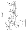
- a hydraulic circuit for supplying pressure oil to the apparatus of the present invention to cause motors, cylinders and the like to perform their predetermined operation is not limited to the embodiment shown in FIG. 3.
- an electric angle detection mechanism is actuated at the time when a defined torque value reached to provide an extra turning through a predetermined angle.
- Reference numeral 1 designates a work table provided with a roller conveyor, 2 a shoe track and 3 a mounting bolt.
- Reference numeral 4 designates a gate type movable frame, 5 a hydraulic cylinder vertically mounted thereon, 6 a piston, and 7 a piston rod which extends through a cyliner cover 8 and is slidably moved.
- a cap-like outer tube 10 is mounted on an extreme end 7a of the piston rod through a thrust bearing 9, the outer tube receiving therein the cylinder 5.
- Reference numeral 11 designates an oil port which extends through an axis of the rod 7, the upper end of which has a hose connected thereto through a swivel joint 12, the lower end thereof being opened at 11a within the cylinder.
- the outer tube 10 is moved up and down together with the piston and rotates around the cylinder.
- Reference numeral 13 designates a main frame fixedly mounted in the outer periphery of the outer tube, 14 a motor, and 15 an oil tank housing therein an oil pump.
- Reference numeral 16 designates a drive shaft with a wrench socket mounted thereon, the drive shaft being supported in a sleeve 17 and carrying a pulley 18 and a lower jaw 27 of a clutch 25.
- Reference numeral 19 designates a belt, 20 a pulley, and 21 a high speed low torque hydraulic motor.
- Reference numeral 22 designates a low speed high torque hydraulic motor, 23 a reduction gear, and 24 an output shaft.
- Reference numeral 25 designates the jaw clutch composed of an upper jaw 26 and the lower jaw 27.
- the upper jaw 26 is slidably movable with respect to the output shaft 24, for example by actuation of a cylinder, for engagement with the lower jaw 27.
- An extreme end 24 a of the output shaft is fitted into the lower jaw 27, the said extreme end being supported through a thrust plate 28.
- a fork 32 engaged with a circumferential groove 29 of the upper jaw clutch 26 is mounted on an extended output shaft 31 of a cylinder 30, and the clutch 25 is turned ON and OFF by the actuation of the cylinder 30.
- Reference numeral 31a designates a return spring, 33 a slit disc and 34 a photo-sensor which is used to set a rotational angle in case of additional fastening or additional turning.
- reference numeral 40 designates an oil pump, and 41 a relief valve, which is set to 350 kg/cm2, for example.
- Reference numeral 42 designates an electromagnetic switching valve, 43 a switching valve actuated in case of additional turning, and 44 a relief valve for adjusting pressure corresponding to a bolt fastening torque.
- Reference numeral 45 designates a reduction valve which acts irrespective of the rotational direction of the high torque motor 22 to supply reduced pressure oil to the clutch switching cylinder 30.
- Reference numeral 46 designates an electromagnetic valve for supplying and stopping pressure oil.
- Reference numeral 47 designates a reduction valve which supplies pressure oil, for example, of 23 kg/cm2, to a low pressure line 48.
- Reference numeral 49 designates an electromagnetic switching valve for supplying or discharging pressure oil from the cylinder 5 to move upwardly the main frame 13, and 50 a throttle valve which adjusts the descending speed of the main frame.
- Reference numeral 51 designates an electromagnetic valve for switching the rotational direction of the low torque motor 21, and 52 a pressure switch for setting pressure to be switched from the low torque motor 21 to the high torque motor 22.
- Reference numeral 53 designates a control box, and 54 an operating handle for adjusting the rotational direction and rotational speed of the low and high torque motors and turning the main frame itself in a horizontal direction.
- the socket wrench is fitted into the shoe bolt head by upward and downward movement of the cylinder 5 by way of the operating handle 54 and a switch (not shown) on a control panel.
- the pressure switch 52 is actuated to switch the electromagnetic valve 42 in a predetermined direction, and at the same time, the electromagnetic valve 46 is actuated to switch the port, and therefore, the pressure oil is supplied to the cylinder 30 to cause the clutch 25 to be engaged.
- the motor is once stopped by the operation of the handle, and the hydraulic circuit is made to assume the FIG. 3 state.
- the high speed torque motor 21 is rotated to rotate the bolt at a high speed.
- the shoe bolt is first rotated at a high speed by the low pressure torque motor 21 and fastened. As the fastening torque increases, the pressure switch 52 is actuated to switch the low pressure torque motor 21 to the high torque motor 22, and the clutch 25 is engaged and the bolt is fastened with a defined torque corresponding to the set pressure of the relief valve 44.
- the switching valve 43 is switched from the control panel to render the relief valve 44 inoperative.
- the additional turning angle detection means may comprises well-known means such as a disc cam and a limit switch.
- the low torque motor is switched to the high torque motor and vice versa to effect operation. Therefore, the efficient operation can be accomplished and in addition, the upward and downward movement of the main frame is carried out by the lifting cylinder, and therefore, the overall height of the apparatus can be designed to be low.
- the setting of the switching torque of the high and low torque motors and the switching of the clutch can be made simply and positively, and the operation is simple.
Landscapes
- Engineering & Computer Science (AREA)
- Mechanical Engineering (AREA)
- Details Of Spanners, Wrenches, And Screw Drivers And Accessories (AREA)
Applications Claiming Priority (2)
| Application Number | Priority Date | Filing Date | Title |
|---|---|---|---|
| JP63243690A JPH0295579A (ja) | 1988-09-28 | 1988-09-28 | 高トルク油圧シューボルトレンチ |
| JP243690/88 | 1988-09-28 |
Publications (2)
| Publication Number | Publication Date |
|---|---|
| EP0361634A1 true EP0361634A1 (fr) | 1990-04-04 |
| EP0361634B1 EP0361634B1 (fr) | 1992-05-06 |
Family
ID=17107537
Family Applications (1)
| Application Number | Title | Priority Date | Filing Date |
|---|---|---|---|
| EP89301880A Expired EP0361634B1 (fr) | 1988-09-28 | 1989-02-24 | Visseuse hydraulique |
Country Status (5)
| Country | Link |
|---|---|
| US (1) | US5005654A (fr) |
| EP (1) | EP0361634B1 (fr) |
| JP (1) | JPH0295579A (fr) |
| CA (1) | CA1314130C (fr) |
| DE (1) | DE68901438D1 (fr) |
Cited By (8)
| Publication number | Priority date | Publication date | Assignee | Title |
|---|---|---|---|---|
| FR2709085A1 (fr) * | 1993-08-18 | 1995-02-24 | Bosch Gmbh Robert | Dispositif pour serrer des liaisons à vis. |
| EP0679762A1 (fr) * | 1994-04-28 | 1995-11-02 | GEORG ROBEL GmbH & Co. | Machine Visseuse |
| FR2749788A1 (fr) * | 1996-06-12 | 1997-12-19 | Chaffoteaux Et Maury | Visseuse automatique d'atelier |
| WO2009135201A3 (fr) * | 2008-05-02 | 2010-02-25 | Dale Francis | Système amélioré de clé dynamométrique doté de multiples points d’application de couple |
| US7993691B2 (en) | 2004-10-25 | 2011-08-09 | Nestec S.A. | Capsule with sealing means and its use in producing a beverage |
| US8304006B2 (en) | 2006-03-31 | 2012-11-06 | Nestec S.A. | Capsule with outer sealing material pressurized by fluid and method and system for using same |
| CN106736479A (zh) * | 2016-12-30 | 2017-05-31 | 东莞市泰诚光电有限公司 | 主动型扭力测量仪 |
| CN110961904A (zh) * | 2019-12-27 | 2020-04-07 | 长春一东离合器股份有限公司 | 自动旋转铆接双工位设备 |
Families Citing this family (8)
| Publication number | Priority date | Publication date | Assignee | Title |
|---|---|---|---|---|
| US5186262A (en) * | 1991-10-30 | 1993-02-16 | Caterpillar Inc. | Powered tool apparatus |
| AU1553595A (en) * | 1994-06-17 | 1996-07-10 | Dale Francis | Improved torque wrench system |
| US6289769B1 (en) * | 1999-12-08 | 2001-09-18 | Honda Of America Mfg., Inc. | Electromagnetic nutrunner socket collar |
| US6553873B2 (en) | 2000-05-03 | 2003-04-29 | Power Tork Hydraulics, Inc. | Hydraulic wrench control valve systems |
| EP1329294A1 (fr) * | 2002-01-21 | 2003-07-23 | Hewlett-Packard Company, A Delaware Corporation | Outil entraine en rotation |
| US7146880B1 (en) | 2004-12-06 | 2006-12-12 | Francis Services, Inc. | Torque wrench system |
| CN102501211A (zh) * | 2011-11-03 | 2012-06-20 | 重庆鼎运机电有限公司 | 一种液压扳手 |
| US12313096B2 (en) * | 2020-12-21 | 2025-05-27 | One Pass Innovators, LLC | Forklift hydraulic motor based industrial driver apparatus |
Citations (5)
| Publication number | Priority date | Publication date | Assignee | Title |
|---|---|---|---|---|
| DE2718342A1 (de) * | 1977-04-25 | 1978-10-26 | Mayer Gmbh Maschbau M | Eindrehvorrichtung fuer beschlaege |
| DE2807677B2 (de) * | 1978-02-23 | 1980-04-03 | Mannesmann Demag Ag, 4100 Duisburg | Hydraulisches Schraubgerät |
| DE3243047A1 (de) * | 1981-11-23 | 1983-05-26 | Atlas Copco AB, Nacka | Pneumatischer motorschrauber mit zwei motoren |
| US4403663A (en) * | 1981-04-13 | 1983-09-13 | Wolff Manufacturing Company | Power-operated torque wrench |
| DE3210889A1 (de) * | 1982-03-25 | 1983-09-29 | Robert Bosch Gmbh, 7000 Stuttgart | Schraubvorrichtung |
Family Cites Families (9)
| Publication number | Priority date | Publication date | Assignee | Title |
|---|---|---|---|---|
| US3108507A (en) * | 1962-02-14 | 1963-10-29 | Rodgers Hydraulic Inc | Power operated wrench |
| US3142210A (en) * | 1962-06-22 | 1964-07-28 | Rodgers Hydraulic Inc | Power operated wrench with two-speed drive |
| US3507173A (en) * | 1968-07-19 | 1970-04-21 | Chicago Pneumatic Tool Co | Two-speed nut-runner having two air motors acting as main and auxiliary drivers of a dual-drive planetary gear system |
| US3529513A (en) * | 1968-11-19 | 1970-09-22 | Chicago Pneumatic Tool Co | Two-speed nut-running tool with tandem motors |
| US3586115A (en) * | 1969-10-29 | 1971-06-22 | Chicago Pneumatic Tool Co | Two-speed dual drive stall torque nut running tool |
| US3686983A (en) * | 1970-07-20 | 1972-08-29 | Thor Power Tool Co | Torque applying and tension controlling device |
| JPS5233840B2 (fr) * | 1973-04-06 | 1977-08-31 | ||
| US4432257A (en) * | 1982-05-17 | 1984-02-21 | Caterpillar Mitsubishi Limited | Shoe bolt securing and removing apparatus |
| JPS60255333A (ja) * | 1984-05-28 | 1985-12-17 | Maruma Jusharyo Kk | シユ−ボルト用油圧レンチ |
-
1988
- 1988-09-28 JP JP63243690A patent/JPH0295579A/ja active Pending
-
1989
- 1989-02-21 CA CA000591668A patent/CA1314130C/fr not_active Expired - Fee Related
- 1989-02-24 EP EP89301880A patent/EP0361634B1/fr not_active Expired
- 1989-02-24 DE DE8989301880T patent/DE68901438D1/de not_active Expired - Fee Related
- 1989-12-18 US US07/455,934 patent/US5005654A/en not_active Expired - Lifetime
Patent Citations (5)
| Publication number | Priority date | Publication date | Assignee | Title |
|---|---|---|---|---|
| DE2718342A1 (de) * | 1977-04-25 | 1978-10-26 | Mayer Gmbh Maschbau M | Eindrehvorrichtung fuer beschlaege |
| DE2807677B2 (de) * | 1978-02-23 | 1980-04-03 | Mannesmann Demag Ag, 4100 Duisburg | Hydraulisches Schraubgerät |
| US4403663A (en) * | 1981-04-13 | 1983-09-13 | Wolff Manufacturing Company | Power-operated torque wrench |
| DE3243047A1 (de) * | 1981-11-23 | 1983-05-26 | Atlas Copco AB, Nacka | Pneumatischer motorschrauber mit zwei motoren |
| DE3210889A1 (de) * | 1982-03-25 | 1983-09-29 | Robert Bosch Gmbh, 7000 Stuttgart | Schraubvorrichtung |
Cited By (14)
| Publication number | Priority date | Publication date | Assignee | Title |
|---|---|---|---|---|
| FR2709085A1 (fr) * | 1993-08-18 | 1995-02-24 | Bosch Gmbh Robert | Dispositif pour serrer des liaisons à vis. |
| US5617924A (en) * | 1993-08-18 | 1997-04-08 | Robert Bosch Gmbh | Arrangement for tightening screw connections |
| EP0679762A1 (fr) * | 1994-04-28 | 1995-11-02 | GEORG ROBEL GmbH & Co. | Machine Visseuse |
| FR2749788A1 (fr) * | 1996-06-12 | 1997-12-19 | Chaffoteaux Et Maury | Visseuse automatique d'atelier |
| US7993691B2 (en) | 2004-10-25 | 2011-08-09 | Nestec S.A. | Capsule with sealing means and its use in producing a beverage |
| US8304006B2 (en) | 2006-03-31 | 2012-11-06 | Nestec S.A. | Capsule with outer sealing material pressurized by fluid and method and system for using same |
| US8020626B2 (en) | 2008-05-02 | 2011-09-20 | Dale Francis | Torque wrench system having multiple torque stations |
| US8157018B2 (en) | 2008-05-02 | 2012-04-17 | Francis Services, Inc. | Torque wrench system having multiple torque stations |
| WO2009135201A3 (fr) * | 2008-05-02 | 2010-02-25 | Dale Francis | Système amélioré de clé dynamométrique doté de multiples points d’application de couple |
| US8347972B2 (en) | 2008-05-02 | 2013-01-08 | Francis Services, Inc. | Torque wrench system having multiple torque stations |
| US8640780B2 (en) | 2008-05-02 | 2014-02-04 | Francis Services, Inc. | Torque wrench system having multiple torque stations |
| US9890599B2 (en) | 2008-05-02 | 2018-02-13 | Francis Torque Service, Llc | Torque wrench system having multiple torque stations |
| CN106736479A (zh) * | 2016-12-30 | 2017-05-31 | 东莞市泰诚光电有限公司 | 主动型扭力测量仪 |
| CN110961904A (zh) * | 2019-12-27 | 2020-04-07 | 长春一东离合器股份有限公司 | 自动旋转铆接双工位设备 |
Also Published As
| Publication number | Publication date |
|---|---|
| DE68901438D1 (de) | 1992-06-11 |
| EP0361634B1 (fr) | 1992-05-06 |
| CA1314130C (fr) | 1993-03-09 |
| JPH0295579A (ja) | 1990-04-06 |
| US5005654A (en) | 1991-04-09 |
Similar Documents
| Publication | Publication Date | Title |
|---|---|---|
| EP0361634B1 (fr) | Visseuse hydraulique | |
| CA2133858A1 (fr) | Mecanisme d'entrainement reversible | |
| US7427258B2 (en) | Counter-rotating spindle transmission | |
| US5167400A (en) | Has invented certain and useful improvements in control device for lifting winches, in particular for drilling rigs | |
| US5058470A (en) | Sawing cycle control system for an undercut swing saw | |
| US6543345B1 (en) | Sudden braking apparatus for press | |
| JP2001277176A (ja) | 旋回装置 | |
| CN1249359C (zh) | 建筑机械的油压控制装置 | |
| EP0491944A4 (en) | Speed change controller of running hydraulic motor | |
| CN110194412A (zh) | 抓具及抓料机 | |
| KR100215145B1 (ko) | 모터 작동식 프레스 기구 | |
| JP3474197B2 (ja) | 同期形直結駆動装置を備えた静圧駆動装置 | |
| JPH04105795A (ja) | スクリュープレスの運転制御装置 | |
| SU1442427A1 (ru) | Привод ползуна механического пресса | |
| EP4235354A3 (fr) | Dispositif de commande à distance et mécanisme de fonctionnement pour eingin de travail | |
| EP0983840B1 (fr) | Presse avec entraínement à came | |
| KR960006676Y1 (ko) | 분할회전 이동테이블의 구동장치 | |
| JP2528476B2 (ja) | プレスのスロ―インチング装置 | |
| US4995782A (en) | Apparatus for rotating a wrist of a robot | |
| JPH10109234A (ja) | 自動ねじ締め機 | |
| EP0663519A2 (fr) | Dispositif pour commander un moteur à combustion | |
| JPH0111438Y2 (fr) | ||
| JPH0357408Y2 (fr) | ||
| CN114055841A (zh) | 一种高速压机重启方法、重启系统和高速压机 | |
| JPH0653039U (ja) | 軸スライド軸調心形ドライバー |
Legal Events
| Date | Code | Title | Description |
|---|---|---|---|
| PUAI | Public reference made under article 153(3) epc to a published international application that has entered the european phase |
Free format text: ORIGINAL CODE: 0009012 |
|
| AK | Designated contracting states |
Kind code of ref document: A1 Designated state(s): DE FR GB IT |
|
| 17P | Request for examination filed |
Effective date: 19900508 |
|
| 17Q | First examination report despatched |
Effective date: 19910911 |
|
| GRAA | (expected) grant |
Free format text: ORIGINAL CODE: 0009210 |
|
| AK | Designated contracting states |
Kind code of ref document: B1 Designated state(s): DE FR GB IT |
|
| REF | Corresponds to: |
Ref document number: 68901438 Country of ref document: DE Date of ref document: 19920611 |
|
| ITF | It: translation for a ep patent filed | ||
| ET | Fr: translation filed | ||
| PLBE | No opposition filed within time limit |
Free format text: ORIGINAL CODE: 0009261 |
|
| STAA | Information on the status of an ep patent application or granted ep patent |
Free format text: STATUS: NO OPPOSITION FILED WITHIN TIME LIMIT |
|
| 26N | No opposition filed | ||
| PGFP | Annual fee paid to national office [announced via postgrant information from national office to epo] |
Ref country code: FR Payment date: 19990209 Year of fee payment: 11 |
|
| PGFP | Annual fee paid to national office [announced via postgrant information from national office to epo] |
Ref country code: GB Payment date: 19990225 Year of fee payment: 11 |
|
| PGFP | Annual fee paid to national office [announced via postgrant information from national office to epo] |
Ref country code: DE Payment date: 19990305 Year of fee payment: 11 |
|
| PG25 | Lapsed in a contracting state [announced via postgrant information from national office to epo] |
Ref country code: GB Free format text: LAPSE BECAUSE OF NON-PAYMENT OF DUE FEES Effective date: 20000224 |
|
| GBPC | Gb: european patent ceased through non-payment of renewal fee |
Effective date: 20000224 |
|
| PG25 | Lapsed in a contracting state [announced via postgrant information from national office to epo] |
Ref country code: FR Free format text: LAPSE BECAUSE OF NON-PAYMENT OF DUE FEES Effective date: 20001031 |
|
| PG25 | Lapsed in a contracting state [announced via postgrant information from national office to epo] |
Ref country code: DE Free format text: LAPSE BECAUSE OF NON-PAYMENT OF DUE FEES Effective date: 20001201 |
|
| REG | Reference to a national code |
Ref country code: FR Ref legal event code: ST |
|
| PG25 | Lapsed in a contracting state [announced via postgrant information from national office to epo] |
Ref country code: IT Free format text: LAPSE BECAUSE OF NON-PAYMENT OF DUE FEES;WARNING: LAPSES OF ITALIAN PATENTS WITH EFFECTIVE DATE BEFORE 2007 MAY HAVE OCCURRED AT ANY TIME BEFORE 2007. THE CORRECT EFFECTIVE DATE MAY BE DIFFERENT FROM THE ONE RECORDED. Effective date: 20050224 |