EP0361642A2 - Verbindungsanschluss für Lautsprecher - Google Patents
Verbindungsanschluss für Lautsprecher Download PDFInfo
- Publication number
- EP0361642A2 EP0361642A2 EP89304923A EP89304923A EP0361642A2 EP 0361642 A2 EP0361642 A2 EP 0361642A2 EP 89304923 A EP89304923 A EP 89304923A EP 89304923 A EP89304923 A EP 89304923A EP 0361642 A2 EP0361642 A2 EP 0361642A2
- Authority
- EP
- European Patent Office
- Prior art keywords
- housing portion
- terminal unit
- coupler
- speaker
- unit
- Prior art date
- Legal status (The legal status is an assumption and is not a legal conclusion. Google has not performed a legal analysis and makes no representation as to the accuracy of the status listed.)
- Granted
Links
Images
Classifications
-
- H—ELECTRICITY
- H01—ELECTRIC ELEMENTS
- H01R—ELECTRICALLY-CONDUCTIVE CONNECTIONS; STRUCTURAL ASSOCIATIONS OF A PLURALITY OF MUTUALLY-INSULATED ELECTRICAL CONNECTING ELEMENTS; COUPLING DEVICES; CURRENT COLLECTORS
- H01R24/00—Two-part coupling devices, or either of their cooperating parts, characterised by their overall structure
- H01R24/66—Two-part coupling devices, or either of their cooperating parts, characterised by their overall structure with pins, blades or analogous contacts and secured to apparatus or structure, e.g. to a wall
-
- H—ELECTRICITY
- H04—ELECTRIC COMMUNICATION TECHNIQUE
- H04R—LOUDSPEAKERS, MICROPHONES, GRAMOPHONE PICK-UPS OR LIKE ACOUSTIC ELECTROMECHANICAL TRANSDUCERS; ELECTRIC HEARING AIDS; PUBLIC ADDRESS SYSTEMS
- H04R1/00—Details of transducers, loudspeakers or microphones
- H04R1/06—Arranging circuit leads; Relieving strain on circuit leads
-
- H—ELECTRICITY
- H01—ELECTRIC ELEMENTS
- H01R—ELECTRICALLY-CONDUCTIVE CONNECTIONS; STRUCTURAL ASSOCIATIONS OF A PLURALITY OF MUTUALLY-INSULATED ELECTRICAL CONNECTING ELEMENTS; COUPLING DEVICES; CURRENT COLLECTORS
- H01R2103/00—Two poles
-
- H—ELECTRICITY
- H01—ELECTRIC ELEMENTS
- H01R—ELECTRICALLY-CONDUCTIVE CONNECTIONS; STRUCTURAL ASSOCIATIONS OF A PLURALITY OF MUTUALLY-INSULATED ELECTRICAL CONNECTING ELEMENTS; COUPLING DEVICES; CURRENT COLLECTORS
- H01R4/00—Electrically-conductive connections between two or more conductive members in direct contact, i.e. touching one another; Means for effecting or maintaining such contact; Electrically-conductive connections having two or more spaced connecting locations for conductors and using contact members penetrating insulation
- H01R4/06—Riveted connections
Definitions
- the present invention relates to a coupler terminal unit for a speaker unit, and more particularly, to a type thereof which requires only a minimized attachment space.
- a speaker unit is generally provided with a coupler terminal unit for receiving therein an input sound reproduction signal.
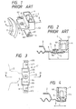
- One conventional coupler terminal unit is shown in Figs. 1 and 2.
- the conventional coupler terminol unit C is fixedly connected to a tongue or attachment piece 3 formed with a hole 3a.
- the attachment piece 3 extends from an outer peripheral edge portion of a speaker frame 2 provided with a magnetic circuit. In other words, the attachment piece 3 extends outwardly in radial direction of the speaker frame 2.
- the terminal unit C includes a flat plate portion C1 formed with a hole 10 and a rectangular housing portion C2 integral with the flat plate portion C1.
- the flat plate portion C1 is secured with a terminal piece 6 formed with upstanding cut pieces 6X and notches 6Y for connecting lead lines or litz wires (not shown).
- the housing portion C2 includes upstanding wall 4 defining an internal space, and input terminals 4A are provided within the space.
- the coupler terminal unit C is connected to the tongue piece 3 of the speaker frame 2 at the flat plate portion C1 by means of an eylet 5.
- the eylet 5 extends through the holes 10 and 3a and then pressure is applied to the ends of the eylet for its deformation. Therefore. the eylet 5 is positioned between the speaker frame 2 and the housing portion C2. Since the housing portion C2 largely protrudes, the housing portion C2 may become an obstacle in order to connect the tongue piece 3 to the flate plate portion C1. That is, the eylet 5 cannot be easily inserted into the holes 10 and 3a, and it would be rather difficult to apply pressure to the eylet 5 for its deformation due to such spacial problem.
- the coupler housing C2 is in direct contact with the vehicle component, vibration of the vehicle may be transmitted to the speaker unit through the coupler terminal unit C. As a result, vibratory noise is directly transmitted to the speaker unit, to thereby modulate reproducing sound.
- an object of the present invention to overcome the above-described drawbacks and to provide an improved coupler terminal unit for a speaker unit.
- Another object of the invention is to provide such improved coupler terminal unit capable of facilitating installation of a speaker unit to a vehicle compartment without any abutment of the coupler unit with the vehicle component, to thereby provide an optimum posture of the speaker unit relative to the vehicle compartment.
- Still another object of the invention is to provide such couple terminal unit which has compact size, to thereby minimize a likelihood of abutting a neighbouring component of a vehicle, to thus avoid sound modulation.
- a coupler terminal unit for a speaker unit which includes a speaker frame and an attachment piece extending radially outwardly from the speaker frame
- the coupler terminal unit comprising: a housing portion having upstanding side walls and a bottom wall for defining an internal space; an eyelet member positioned at the internal space for fixely connecting the housing portion to the attachment piece; and a pair of terminal pieces each extending from each of the side walls of the housing portion.
- a coupler terminal unit according to one embodiment of this invention will be described with reference to Figs. 3 and 4 wherein like parts and components are designated by the same reference numerals and characters as those shown in Figs. 1 and 2.
- a coupler terminal unit C′ includes a rectangular housing portion C2′, and there is no member corresponding to the flat plate portion C1 in the conventional unit C.
- the housing portion C2′ includes an upstanding wall 4′ and a bottom wall 4′a, and input terminals 4′A are implanted on the bottom wall 4′a.
- each of the input terminals 4′A is contiguous with each of terminal pieces 6′. That is, a plate member is bent into L shape, and an upstanding portion of the plate member is implanted on the bottom wall 4′a and functions as the input terminal 4′A, whereas remaining portion of the plate member functions as the terminal piece 6′ directed in a direction the same as the longitudinal direction of the housing portion 4′.
- the terminal pieces 6′ is formed with an upstanding cut piece 6′X and a notch 6′Y for connecting Litz wires (not shown). As a result, the terminal pieces extend in the longitudinal direction of the housing portion C2′ which direction is perpendicular to the extending direction of the attachment piece 3′.
- an eyelet 5 is positioned within the housing portion C2′, so that the coupler terminal unit C′ is fixedly coupled to a tongue piece or attachment piece 3′ of a speaker frame 2. As shown, the eylet 5 is provided at a central portion of the bottom wall 4′a and between the input terminals 4′A and 4′A.
- a projecting length L′ of the tongue piece 3′ can be reduced, since the tongue piece is directly connected to the housing portion C2′.
- the housing portion C2′ can be positioned much closer to the speaker frame 2 in comparison with the conventional arrangement.
- the coupler terminal unit can be positioned close to the outer periperal edge portion of the speaker frame in radial direction thereof. Therefore, mechanical abutment or interference between the coupler terminal unit and a vehicle component can be minimized when the speaker unit is intended to be installed on a limitted space of a vehicle compartment. Further, the eyelet fixing work can be achieved easily, since the eyelet fixing work is not carried out at the blind portion (at the flat plate portion C1 behind the bulk of housing portion C2), but can be carried out at an open area (on the housing portion C2′).
Landscapes
- Physics & Mathematics (AREA)
- Engineering & Computer Science (AREA)
- Acoustics & Sound (AREA)
- Signal Processing (AREA)
- Audible-Bandwidth Dynamoelectric Transducers Other Than Pickups (AREA)
- Details Of Audible-Bandwidth Transducers (AREA)
Applications Claiming Priority (2)
| Application Number | Priority Date | Filing Date | Title |
|---|---|---|---|
| JP240426/88 | 1988-09-24 | ||
| JP63240426A JPH0640500B2 (ja) | 1988-09-24 | 1988-09-24 | スピーカ用カプラ端子装置 |
Publications (3)
| Publication Number | Publication Date |
|---|---|
| EP0361642A2 true EP0361642A2 (de) | 1990-04-04 |
| EP0361642A3 EP0361642A3 (en) | 1990-12-19 |
| EP0361642B1 EP0361642B1 (de) | 1996-01-03 |
Family
ID=17059306
Family Applications (1)
| Application Number | Title | Priority Date | Filing Date |
|---|---|---|---|
| EP89304923A Expired - Lifetime EP0361642B1 (de) | 1988-09-24 | 1989-05-16 | Verbindungsanschluss für Lautsprecher |
Country Status (4)
| Country | Link |
|---|---|
| US (1) | US4966558A (de) |
| EP (1) | EP0361642B1 (de) |
| JP (1) | JPH0640500B2 (de) |
| DE (1) | DE68925326T2 (de) |
Cited By (6)
| Publication number | Priority date | Publication date | Assignee | Title |
|---|---|---|---|---|
| EP0749262A1 (de) * | 1995-06-15 | 1996-12-18 | Kabushiki Kaisha Kenwood | Lautsprecher mit Verbindungsanordnung |
| FR2740932A1 (fr) * | 1995-11-07 | 1997-05-09 | Amp France | Assemblage de connexion d'un haut-parleur |
| US5757945A (en) * | 1995-04-12 | 1998-05-26 | Kabushiki Kaisha Kenwood | Terminal for speaker |
| US5850462A (en) * | 1994-12-28 | 1998-12-15 | Kabushiki Kaisha Kenwood | Speaker component, speaker, and its manufacturing method |
| EP0994526A3 (de) * | 1998-10-16 | 2002-01-30 | GRUNDIG Aktiengesellschaft | Stecker und Klemmbuchse zum Anschluss eines Lautsprechers |
| EP1858288A1 (de) * | 2006-05-17 | 2007-11-21 | Pioneer Corporation | Lautsprechereinrichtung |
Families Citing this family (3)
| Publication number | Priority date | Publication date | Assignee | Title |
|---|---|---|---|---|
| US6836029B2 (en) | 2001-11-28 | 2004-12-28 | International Business Machines Corporation | Micro-electromechanical switch having a conductive compressible electrode |
| JP4592500B2 (ja) * | 2005-06-02 | 2010-12-01 | パイオニア株式会社 | スピーカー装置及びその製造方法 |
| JP2009177439A (ja) * | 2008-01-24 | 2009-08-06 | Funai Electric Co Ltd | スピーカ装置およびテレビジョン |
Family Cites Families (6)
| Publication number | Priority date | Publication date | Assignee | Title |
|---|---|---|---|---|
| US1712212A (en) * | 1925-10-12 | 1929-05-07 | Amsco Products Inc | Electron-discharge-tube socket |
| US3510937A (en) * | 1968-02-05 | 1970-05-12 | Heppner Mfg Co | Method of installing loudspeaker lead wires |
| FR2464613A1 (fr) * | 1979-09-03 | 1981-03-06 | Balbi Richard | Dispositif d'asservissement pour haut-parleur du type electromagnetique d'un appareil radio ou d'un lecteur de bandes magnetique basse tension |
| JPS6184991A (ja) * | 1984-10-02 | 1986-04-30 | Matsushita Electric Ind Co Ltd | スピ−カ装置 |
| NL8600267A (nl) * | 1986-02-04 | 1987-09-01 | Philips Nv | Elektrodynamische omzetter. |
| FR2602945B1 (fr) * | 1986-07-28 | 1988-11-10 | Labinal | Dispositif de raccordement electrique du moteur d'un haut parleur |
-
1988
- 1988-09-24 JP JP63240426A patent/JPH0640500B2/ja not_active Expired - Fee Related
-
1989
- 1989-05-16 DE DE68925326T patent/DE68925326T2/de not_active Expired - Lifetime
- 1989-05-16 EP EP89304923A patent/EP0361642B1/de not_active Expired - Lifetime
- 1989-05-16 US US07/352,520 patent/US4966558A/en not_active Expired - Lifetime
Cited By (6)
| Publication number | Priority date | Publication date | Assignee | Title |
|---|---|---|---|---|
| US5850462A (en) * | 1994-12-28 | 1998-12-15 | Kabushiki Kaisha Kenwood | Speaker component, speaker, and its manufacturing method |
| US5757945A (en) * | 1995-04-12 | 1998-05-26 | Kabushiki Kaisha Kenwood | Terminal for speaker |
| EP0749262A1 (de) * | 1995-06-15 | 1996-12-18 | Kabushiki Kaisha Kenwood | Lautsprecher mit Verbindungsanordnung |
| FR2740932A1 (fr) * | 1995-11-07 | 1997-05-09 | Amp France | Assemblage de connexion d'un haut-parleur |
| EP0994526A3 (de) * | 1998-10-16 | 2002-01-30 | GRUNDIG Aktiengesellschaft | Stecker und Klemmbuchse zum Anschluss eines Lautsprechers |
| EP1858288A1 (de) * | 2006-05-17 | 2007-11-21 | Pioneer Corporation | Lautsprechereinrichtung |
Also Published As
| Publication number | Publication date |
|---|---|
| EP0361642A3 (en) | 1990-12-19 |
| DE68925326T2 (de) | 1996-08-22 |
| DE68925326D1 (de) | 1996-02-15 |
| EP0361642B1 (de) | 1996-01-03 |
| JPH0287489A (ja) | 1990-03-28 |
| US4966558A (en) | 1990-10-30 |
| JPH0640500B2 (ja) | 1994-05-25 |
Similar Documents
| Publication | Publication Date | Title |
|---|---|---|
| US6709291B1 (en) | Apparatus and method for shielding a circuit from electromagnetic interference | |
| EP0417648B1 (de) | Karte mit integrierter Schaltung | |
| JP2625546B2 (ja) | 機器のカバーのための取付装置 | |
| EP0361642A2 (de) | Verbindungsanschluss für Lautsprecher | |
| US5432340A (en) | Photoelectric converter with photoelectric converter element mounted in shielding case | |
| JP3062928B2 (ja) | コンタクト | |
| EP0765009A2 (de) | Randverbinder für Leiterplatten und Anschlusselement dafür | |
| JP3607241B2 (ja) | 電気コネクタ | |
| US5259796A (en) | Electrical socket contact | |
| EP1307070B1 (de) | Kabelstecker für einen Lautsprecher | |
| CA2054661C (en) | Portable electronic apparatus | |
| US6769815B2 (en) | Optical connector and shield case | |
| JP3985386B2 (ja) | スピーカ用ターミナルおよびこれを用いたスピーカ | |
| US6018190A (en) | I/O card device and method for making the same | |
| JPH0541593Y2 (de) | ||
| JPH0641371Y2 (ja) | アンテナ装置 | |
| JP2882288B2 (ja) | 電気接続箱 | |
| JP2731393B2 (ja) | 配線器具 | |
| JPS63120589A (ja) | スピ−カ | |
| JPH07240244A (ja) | 同軸ケーブル取付構造 | |
| JPH10271656A (ja) | ジョイント部の固定構造 | |
| JP2561566Y2 (ja) | 圧電ブザー | |
| US6318688B1 (en) | Bracket | |
| JPS63114053A (ja) | 電子機器 | |
| JPH07312270A (ja) | コネクタ取付装置 |
Legal Events
| Date | Code | Title | Description |
|---|---|---|---|
| PUAI | Public reference made under article 153(3) epc to a published international application that has entered the european phase |
Free format text: ORIGINAL CODE: 0009012 |
|
| AK | Designated contracting states |
Kind code of ref document: A2 Designated state(s): DE GB |
|
| PUAL | Search report despatched |
Free format text: ORIGINAL CODE: 0009013 |
|
| AK | Designated contracting states |
Kind code of ref document: A3 Designated state(s): DE GB |
|
| 17P | Request for examination filed |
Effective date: 19910531 |
|
| 17Q | First examination report despatched |
Effective date: 19920701 |
|
| GRAA | (expected) grant |
Free format text: ORIGINAL CODE: 0009210 |
|
| AK | Designated contracting states |
Kind code of ref document: B1 Designated state(s): DE GB |
|
| REF | Corresponds to: |
Ref document number: 68925326 Country of ref document: DE Date of ref document: 19960215 |
|
| REG | Reference to a national code |
Ref country code: GB Ref legal event code: 746 Effective date: 19960412 |
|
| PLBE | No opposition filed within time limit |
Free format text: ORIGINAL CODE: 0009261 |
|
| STAA | Information on the status of an ep patent application or granted ep patent |
Free format text: STATUS: NO OPPOSITION FILED WITHIN TIME LIMIT |
|
| 26N | No opposition filed | ||
| REG | Reference to a national code |
Ref country code: GB Ref legal event code: IF02 |
|
| APAH | Appeal reference modified |
Free format text: ORIGINAL CODE: EPIDOSCREFNO |
|
| PGFP | Annual fee paid to national office [announced via postgrant information from national office to epo] |
Ref country code: DE Payment date: 20080522 Year of fee payment: 20 |
|
| PGFP | Annual fee paid to national office [announced via postgrant information from national office to epo] |
Ref country code: GB Payment date: 20080521 Year of fee payment: 20 |
|
| REG | Reference to a national code |
Ref country code: GB Ref legal event code: PE20 Expiry date: 20090515 |
|
| PG25 | Lapsed in a contracting state [announced via postgrant information from national office to epo] |
Ref country code: GB Free format text: LAPSE BECAUSE OF EXPIRATION OF PROTECTION Effective date: 20090515 |