EP0361662A1 - Système d'infusion parentérale de deux liquides avec module d'infusion secondaire - Google Patents
Système d'infusion parentérale de deux liquides avec module d'infusion secondaire Download PDFInfo
- Publication number
- EP0361662A1 EP0361662A1 EP89308227A EP89308227A EP0361662A1 EP 0361662 A1 EP0361662 A1 EP 0361662A1 EP 89308227 A EP89308227 A EP 89308227A EP 89308227 A EP89308227 A EP 89308227A EP 0361662 A1 EP0361662 A1 EP 0361662A1
- Authority
- EP
- European Patent Office
- Prior art keywords
- solution
- primary
- module
- drip chamber
- infusion
- Prior art date
- Legal status (The legal status is an assumption and is not a legal conclusion. Google has not performed a legal analysis and makes no representation as to the accuracy of the status listed.)
- Granted
Links
- 238000001802 infusion Methods 0.000 title claims abstract description 87
- 230000009977 dual effect Effects 0.000 title claims abstract description 26
- 239000000243 solution Substances 0.000 claims abstract description 125
- 239000012530 fluid Substances 0.000 claims abstract description 31
- 239000003182 parenteral nutrition solution Substances 0.000 claims abstract description 9
- 238000001514 detection method Methods 0.000 claims description 7
- 230000000977 initiatory effect Effects 0.000 claims 1
- 230000000994 depressogenic effect Effects 0.000 description 13
- 230000000881 depressing effect Effects 0.000 description 8
- 230000003287 optical effect Effects 0.000 description 8
- 230000007246 mechanism Effects 0.000 description 6
- 230000001276 controlling effect Effects 0.000 description 5
- 238000004891 communication Methods 0.000 description 4
- 230000004888 barrier function Effects 0.000 description 3
- 238000013461 design Methods 0.000 description 3
- 238000000034 method Methods 0.000 description 3
- 238000012544 monitoring process Methods 0.000 description 3
- 230000005540 biological transmission Effects 0.000 description 2
- 238000010586 diagram Methods 0.000 description 2
- 230000001105 regulatory effect Effects 0.000 description 2
- 230000008901 benefit Effects 0.000 description 1
- 230000015572 biosynthetic process Effects 0.000 description 1
- 230000008859 change Effects 0.000 description 1
- 230000008878 coupling Effects 0.000 description 1
- 238000010168 coupling process Methods 0.000 description 1
- 238000005859 coupling reaction Methods 0.000 description 1
- 238000003780 insertion Methods 0.000 description 1
- 230000037431 insertion Effects 0.000 description 1
- 230000003993 interaction Effects 0.000 description 1
- 230000007257 malfunction Effects 0.000 description 1
- 239000012528 membrane Substances 0.000 description 1
- 230000037452 priming Effects 0.000 description 1
- 230000008569 process Effects 0.000 description 1
- 238000012795 verification Methods 0.000 description 1
Images


Classifications
-
- A—HUMAN NECESSITIES
- A61—MEDICAL OR VETERINARY SCIENCE; HYGIENE
- A61M—DEVICES FOR INTRODUCING MEDIA INTO, OR ONTO, THE BODY; DEVICES FOR TRANSDUCING BODY MEDIA OR FOR TAKING MEDIA FROM THE BODY; DEVICES FOR PRODUCING OR ENDING SLEEP OR STUPOR
- A61M5/00—Devices for bringing media into the body in a subcutaneous, intra-vascular or intramuscular way; Accessories therefor, e.g. filling or cleaning devices, arm-rests
- A61M5/14—Infusion devices, e.g. infusing by gravity; Blood infusion; Accessories therefor
-
- A—HUMAN NECESSITIES
- A61—MEDICAL OR VETERINARY SCIENCE; HYGIENE
- A61M—DEVICES FOR INTRODUCING MEDIA INTO, OR ONTO, THE BODY; DEVICES FOR TRANSDUCING BODY MEDIA OR FOR TAKING MEDIA FROM THE BODY; DEVICES FOR PRODUCING OR ENDING SLEEP OR STUPOR
- A61M5/00—Devices for bringing media into the body in a subcutaneous, intra-vascular or intramuscular way; Accessories therefor, e.g. filling or cleaning devices, arm-rests
- A61M5/14—Infusion devices, e.g. infusing by gravity; Blood infusion; Accessories therefor
- A61M5/168—Means for controlling media flow to the body or for metering media to the body, e.g. drip meters, counters ; Monitoring media flow to the body
- A61M5/16804—Flow controllers
- A61M5/16827—Flow controllers controlling delivery of multiple fluids, e.g. sequencing, mixing or via separate flow-paths
-
- Y—GENERAL TAGGING OF NEW TECHNOLOGICAL DEVELOPMENTS; GENERAL TAGGING OF CROSS-SECTIONAL TECHNOLOGIES SPANNING OVER SEVERAL SECTIONS OF THE IPC; TECHNICAL SUBJECTS COVERED BY FORMER USPC CROSS-REFERENCE ART COLLECTIONS [XRACs] AND DIGESTS
- Y10—TECHNICAL SUBJECTS COVERED BY FORMER USPC
- Y10S—TECHNICAL SUBJECTS COVERED BY FORMER USPC CROSS-REFERENCE ART COLLECTIONS [XRACs] AND DIGESTS
- Y10S128/00—Surgery
- Y10S128/13—Infusion monitoring
Definitions
- This invention relates to infusion systems which control the delivery of two sources of parenteral solutions to a patient and, in particular, to apparatus for monitoring and controlling the solutions being delivered in these systems.
- a pinch valve on the controller occludes the secondary tubing set and solution begins to flow from the primary source.
- the delivery of primary solution is monitored by a drop detector and drip chamber on the primary controller, and its flow is controlled by the control valve.
- a check valve in the primary administration set prevents flow of the primary solution while the secondary solution is being delivered.
- U.S. Patent 4,533,347 shows a similar system in which the drip chamber for the primary solution is located in the primary administration set.
- the drop detector for the primary solution is located about this drip chamber, remote from the primary controller.
- each administration set includes a drip chamber and an associated drop detector. Operation of the system is as described for the '592 patent.
- U.S. Patent 4,637,817 shows a dual source infusion system in which each administration set passes through a sequenced pinch valve above the Y-connector.
- the pinch valve alternately opens one of the tubing sets and closes the other, and the flow of parenteral solution is controlled by a pump located on the controller.
- the use of the sequenced pinch valve obviates the need for a check valve in the primary solution line, since the valve permits the flow of only one solution at a time.
- a user To initialize the system prior to fluid delivery, a user must enter flow rate and total dose values into the primary controller. As the values are entered, they are displayed on the primary controller display. The values for the two solution sources are separately entered and displayed. That is, the user first enters the values for one solution source and observes their entry on the display. The display is then cleared, and the user enters and observes the values for the other solution source. During operation of the system, the delivery rate and volume of the solution being delivered at that time are viewed on the display.
- a nurse should be able to immediately note both the progress of secondary solution delivery and the dose previously delivered from the primary source without manipulating the system or interrupting the flow of primary solution.
- a dual source parenteral infusion system which enables a user to unambiguously control and monitor the delivery of the two solutions.
- the primary controller of the system includes means for controlling the rate of fluid delivery, means for entering values for controlling the delivery of the primary solution, and a display for displaying both the entry of the primary solution delivery values and the progress of primary solution delivery.
- a secondary infusion module communicates with the primary controller and is adapted for coupling to the secondary administration set.
- the secondary infusion module includes means for monitoring the delivery of secondary solution, and a display for displaying the progress of secondary solution delivery.
- the secondary infusion module provides a display which is unambiguously located in proximity to the secondary administration set.
- entry of the secondary solution delivery values is provided at the secondary infusion module.
- the user can visually ascertain the parameters for secondary solution delivery directly on the display of the secondary infusion module.
- the secondary infusion module also includes means for opening and occluding a conduit in the secondary administration set as infusion of the secondary solution commences and terminates.
- FIGURE 1 a dual source parenteral infusion system constructed in accordance with the principles of the present invention is shown.
- a source 2 of a primary solution is suspended from a pole 1.
- the primary solution is delivered to a drip chamber 26, about which is mounted a drop detector 4.
- Tubing 8 of a primary solution administration set leads from the drip chamber to a Y-connector 10, and includes an in-line one-way check valve 6.
- the outlet of the Y-connector is connected by common tubing 12 to a precision control valve 22, which is mounted on a primary controller 20.
- An outlet tubing line 14 leads from the control valve 22 to the infusion site.
- a display 28 On the right-hand side of the front of the primary controller 20 is a display 28, which displays values indicating the progress of infusion of the primary solution. Below the display 28 is a group of pushbutton controls 30 for entry of values for controlling infusion of the primary solution. As the values are entered prior to operation of the system they may be viewed on the display 28.
- an interface box 32 At the bottom of the central controller 20 is an interface box 32, which connects the primary controller to the drop dectector 4 and to a secondary infusion module 40 by way of cables 34 and 36.
- a secondary solution source 24 Also suspended from the pole 1 is a secondary solution source 24.
- Tubing 16 of a secondary administration set connects the secondary solution supply to a second input port of the Y-connector 10.
- a second drip chamber Located just below the secondary solution source 24 is a second drip chamber. This drip chamber is not visible in FIGURE 1, as it is located inside the secondary infusion module 40.
- the secondary infusion module mounts around the second drip chamber in the same manner as the drop detector 4 mounts around drip chamber 26.
- the secondary infusion module includes a display area 42 which displays parameters indicating the progress of delivery of the secondary solution. Below the display area is a group of pushbutton controls 44. These controls permit entry of the values governing delivery of the secondary solution directly at the secondary infusion module. As the values are entered they may be visually ascertained directly on the display 42.
- One of the two pushbuttons at the bottom of the secondary infusion module controls an internal mechanism which opens and occludes the tubing line 16 as it passes through the secondary infusion module. The other
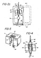
- FIGURE 2a a primary controller 20 is shown.
- a display 28 On the right-hand side of the front of the controller 20 is a display 28.
- an eight character message center 122 which displays error and other status messages.
- the individual characters in the message are each comprised of fourteen individually controlled segments to form the desired alphanumeric characters.
- Below and to the left of the message center is an instrument logo design 124 which pulses when the primary controller is operating.
- Below the logo design are three large numbers which indicate the flow rate in ml/hr at which the primary controller is currently operating. To the left of the numbers is the descriptor "FLOW RATE," and above the numbers are the units of ml/hr.
- the top line represents a fluid code which a user may enter to specify the type of solution being administered.
- the next line specifies the dose remaining to be delivered of the total dose programmed into the controller at the beginning of the procedure.
- the third line specifies the remaining time for completion of the administration of the programmed dose, and the fourth line indicates the volume of the programmed dose already administered.
- Pushbuttons 130 are used to increment or decrement a value during programming of the controller.
- Pushbutton 132 is used to turn the controller off or on.
- the "SELECT” pushbutton 134 is used to select a value which is to be programmed into the controller, such as "dose” or "flow rate.”
- the "SELECT” pushbutton may also be used to change values during fluid delivery by holding the "SELECT” pushbutton down while incrementing or decrementing a value with the up/down pushbuttons.
- Pushbutton 136 is depressed to stop the administration of solution, and pushbutton 138 is depressed to start fluid administration in accordance with the values programmed into the controller.
- the control valve 22 shown in FIGURE 2a is a precision pinch valve which encloses tubing line 12, 14, and is described in greater detail in U.S. Patent 4,559,045. Inside the pinch valve the tubing is engaged between a movable pressure plate and a stationary pressure plate. A precision motor-driven actuator projects from the front of the controller and is in contact with the movable pressure plate to controllably move the movable pressure plate toward and away from the interposed tubing. The tubing is thereby selectively occluded to control the rate of flow of fluid through the outlet tubing 14.
- a drip chamber 80 has a cap 98 with an integrally molded drop former.
- a lip 94 at the bottom of the cap snaps into a retaining ring 54 at the top of a drop detector 56.
- the drip chamber is properly located within the drop detector 56, its presence is detected by a door 60 which is hinged as indicated at 63. Falling drops within the drip chamber are detected by the optical path indicated by the arrows at the top of the chamber and their passage is used by the primary controller to measure the flow of primary solution.
- a precision pinch valve 70 below the drip chamber 80 selectively occludes the outlet tubing 14 to regulate the flow of parenteral solution to the patient.
- the drop detector 4 and the drip chamber 26 of FIGURE 1 are shown in detail in FIGURES 3 and 4.
- the drop detector 4 is seen to comprise a housing which encloses photodiodes and photodetectors for an optical drop detector 62 and an optical level detector 66.
- a spring hinged door 60 is located within the cavity in the center of the housing and projects forward in the absence of a drip chamber in the housing, in which position it blocks the optical path of the drop detector 62.
- At the top of the housing is a split mounting ring 54.
- the drop detector 4 is mounted about the drip chamber 26 in FIGURE 4 by snapping the lip 94 of the spike 95 at the top of the chamber into the mounting ring 54.
- the spike 95 is inserted into a parenteral solution bag or membrane in the cap of the suspended fluid source prior to mounting the drop detector.
- the chamber presses the hinged door 60 to the rear of the cavity, thereby unblocking the optical path of the drop detector 62.
- the drop detector is able to sense the proper mounting of the drip chamber by the deflection of the door 60, and also senses proper priming of the drip chamber by the obscuring of the level detector 66 with fluid while the optics of drop detector 62 are unobscured.
- droplets will fall from the drop former and be detected by the optical drop detector 62.
- a detailed description of the drop detector 4 is presented in U.S. Patent Application SN 117,009, filed November 4, 1987.
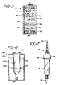
- the secondary infusion module of the present invention is shown in the front and back views of FIGURES 5 and 6.
- a display 42 shown in FIGURE 5.
- a five character message center 72 is located at the top of the display. These fourteen segment characters display alarm and status conditions during the administration of the secondary solution.
- an instrument logo design 74 which pulses during delivery of the secondary solution.
- Below the logo are three large characters 76 which display the flow rate of the solution.
- the descriptor "FLOW RATE” and the flow units of ml/hr are displayed above the flow rate numerals.
- Below the flow rate are three and one-half characters 78 which display the dose being administered, together with the descriptor "DOSE" and the units of ml.
- a series of pushbuttons 44 which are used to program and operate the module 40.
- the "SELECT" pushbutton 82 is depressed to program the module. When this pushbutton is depressed, the descriptor and units of the value being entered flash on the display, and the value is incremented or decremented by depressing the up/down pushbuttons 86.
- the "STANDBY” pushbutton 84 is depressed to stop the administration of the secondary solution and start the administration of the primary solution, or to clear the alarms on the secondary infusion module.
- Below the pushbuttons 86 is a “Load” key 88, which is depressed while mounting the secondary infusion module around the secondary drip chamber.
- An “Infuse” key 90 is depressed to begin the administration of the secondary solution.
- the side of the secondary infusion module is shown in FIGURE 6.
- a cavity 100 in the module is accessible from the side for insertion of the secondary drip chamber shown in FIGURE 7.
- At the top of the module is a mounting ring 92, similar to the mounting ring 54 of the drop detector 4.
- the secondary infusion module is mounted around the secondary drip chamber 81 by inserting the lip 94 of the drip chamber spike 95 into the mounting ring 92.
- the drip chamber 81 is positioned in the optical path of a drop detector 102, 102′, and in the optical path of a low level detector 106, 106′.
- a barrier 93 To properly engage the drip chamber in the cavity 100 a barrier 93 must be withdrawn from the bottom of the cavity 100.
- the barrier is withdrawn by depressing the "Load” key, whereupon the tubing section 16 is located in the passage at the bottom of the cavity.
- the barrier 93 pinches the tubing section 16 closed. Fluid flow is thereby prevented until the "Infuse” key is depressed at the commencement of secondary infusion.
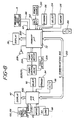
- Control of the dual source infusion system of FIGURE 1 is provided by two microprocessors, one located in the primary controller and another in the secondary infusion module, as shown in block diagram form in FIGURE 8.
- the microprocessor 200 in the primary controller 20 interacts with other components of the primary controller as shown in the FIGURE.
- the microprocessor 200 activates and controls the display 28 and an alarm 208. It also controls a motor 204 for the pump or control valve, which in turn is connected to the pump or valve.
- Fault detector electronics 206 monitors the operation of the pump or valve and informs the microprocessor 200 of the pump or valve operation. Faults detected by the electronics 206 are conditions related to flow, such as slow flow, no flow, or an occlusion at the infusion site. When any of these conditions are detected, the microprocessor 200 will verify them and sound the alarm 208 and cease system operation until the alarm condition is remedied.
- the primary microprocessor 200 receives information on primary solution drop detection from the primary drop detector 4 which indicate an alarm condition, such as high or low solution level in the primary drip chamber, no drops, or a continuous stream of drops. Whenever any of these conditions are detected the microprocessor 200 will verify the problem, activate the alarm and cease system operation.
- an alarm condition such as high or low solution level in the primary drip chamber, no drops, or a continuous stream of drops.
- the primary controller 20 is initially turned on by closure of the on/off switch 132, which connects the microprocessor and other electronics to a power source 210.
- the microprocessor 200 also receives inputs from the standby pushbutton 136, the SELECT pushbutton 134, the infuse pushbutton 138, and the up/down pushbuttons 130.
- the microprocessor 300 in the secondary infusion module 40 activates and controls the display 42.
- the microprocessor 300 receives secondary solution drop detection information from the integral secondary drop detector 102 and level detector 106, in particular drop detection and high or low level information, as well as notification that the drip chamber 81 has been properly mounted.
- the Load key 88, the Infuse key 90, the SELECT pushbutton 82, the STANDBY pushbutton 84, and the up/down pushbuttons 86 also are connected to provide inputs to the microprocessor 300.
- the two microprocessors are interconnected by a 6-line communications bus 250, enclosed within the cable 34.
- the six lines include a transmit line, a receive line, a clock line, a V CC regulated voltage line, a V batt battery voltage line, and a ground line.
- transceivers one of which is located in the interface 32 at the bottom of the primary controller.
- a second transceiver is located in the secondary infusion module 40. Redundant transmissions are employed to assure data integrity.
- An infusion procedure may be commenced using the system of the present invention by starting to administer the secondary solution first, then changing over to administration of the primary solution.
- One advantage of the arrangement of the present invention is that secondary solution administration can be commenced while the administration of primary solution is in progress, whereafter the system will revert back to primary solution administration when the administration of secondary solution is completed. Operation of the system of the present invention will be illustrated by explaining the latter process.
- the container is suspended from the pole, and the primary administration set (including drip chamber 26, tubing section 8, check valve 6, Y-connector 10, tubing section 12, pinch valve 22, 79 or cassette 50, and tubing section 14) is connected to the solution container and primed with solution.
- the primary administration set (including drip chamber 26, tubing section 8, check valve 6, Y-connector 10, tubing section 12, pinch valve 22, 79 or cassette 50, and tubing section 14) is connected to the solution container and primed with solution.
- the primary controller is programmed by entering values for the total dose in ml and the flow rate in ml/hr, using the SELECT pushbutton 134 and the up/down pushbuttons 130. As the values are entered they are verified visually on the primary display 28. When the the primary solution values are properly entered the clamp on the tubing set is released and the infuse pushbuttons 138 is depressed to begin infusion.
- the microprocessor 200 will thereupon execute a series of hardware and software checks to verify that the system is connected and operating properly, and will begin to control the pump or precision valve mechanism to adjust for the desired flow rate. As the infusion proceeds, information on the rate of progress is displayed on the primary display 28.
- the administration of primary solution may be interrupted by the administration of the secondary solution as follows.
- a hook which is a part of the secondary administration set is used to suspend the primary solution container from the pole at a level below that of the secondary solution container.
- the secondary solution container is suspended from the pole and the secondary administration set (including the secondary drip chamber 81 and the tubing line 16) is connected to the container and primed with solution.
- the tubing line 16 is clamped and a needle at the end of tubing section 16 is inserted into the Y-connector 10.
- the secondary infusion module 40 is mounted about the secondary drip chamber 81 by inserting the drip chamber 81 into the cavity at the side of the module while depressing then releasing the Load key.
- the module is then programmed for the values of secondary solution delivery by depressing the SELECT pushbutton 82 and the up/down pushbuttons 86. Entry of the correct values is visually confirmed by viewing the display 42 on the module. The clamp on the administration set is released and delivery of the secondary solution begun by depressing the Infuse key on the module.
- the secondary infusion module As soon as the secondary infusion module is connected to the primary controller, power is provided to the module 40 from the primary controller and the microprocessors in the two units begin exchanging status bytes of information. During this period of initialization the secondary microprocessor 300 executes a series of hardware and software checks to assure that the secondary system is connected and operating properly. Once the Infuse key has been depressed, an intense burst of communication between the two microprocessors begins. The microprocessor 300 sends a burst of twelve 8-bit bytes to the microprocessor 200 over the communications bus 250. This data burst informs the primary controller as to the infusion parameters to be used for controlling the dose and flow rate.
- the received data is echoed back to the module for verification and the primary microprocessor begins to adjust the flow control mechanism for the proper rate of fluid delivery of the secondary solution.
- the two microprocessors resume exchanging status information at a low level.
- the primary controller sends eight-bit bytes to the secondary microprocessor 300, each byte containing a "dose decrement” bit, a primary alarm bit, a "stop infuse” bit, and an unused bit. These four bits are repeated in the last four bits of the byte for redundancy checking. Delivery of the secondary solution commences as the pressure head of the secondary solutions closes the check valve 6 and the secondary solution flows into the pump or control valve mechanism.
- the microprocessor 300 monitors the drop formation and fluid level in the secondary drip chamber 81. Every eight milliseconds the secondary microprocessor 81 transmits an 8-bit status byte to the primary microprocessor. Each byte contains an alarm bit, a drop sense bit, a start/stop bit, and a level bit. These four bits are replicated in the second four bits of the byte for redundancy. Whenever a falling drop is detected in the secondary drip chamber the drop sense bit is set in the transmitted byte, and held for 100 milliseconds for debounce purposes. The start/stop bit is set and held after the Infuse key is depressed, and is released only when secondary infusion is completed.
- the secondary infusion module is shut down and the infusion of primary solution resumes.
- the other bits in the status byte including the alarm bit and the level bit, are checked by the primary microprocessor 200 every 72 milliseconds.
- the level bit is set if the secondary microprocessor detects the presence of fluid at the level of detector 106, 106′ in the secondary drip chamber 81.
- the secondary infusion module When the secondary infusion module is delivering the secondary solution, either after interrupting primary solution delivery or by starting the system with initial delivery of the secondary solution, there are several ways of terminating secondary solution delivery.
- One way is to deliver the programmed dose of secondary solution, whereupon system operation switches over from the secondary module to the primary controller. It is possible to deliver not just a measured dose, but the entire supply of secondary solution.
- the module is programmed to do this by decrementing from a dose of "000" using the up/down keys, whereupon the dose display reads "ALL.”
- the delivery of the full supply of solution is detected by a low level detection in the secondary drip chamber.
- the third type of error is a hardware or software malfunction or communication link problem, which may be detected by either the primary controller or the secondary module.
- the dual source infusion system of FIGURE 1 may be operated by first suspending the solution containers from the pole.
- the primary administration set is connected to the primary solution container and is primed with solution and clamped.
- the secondary administration set is connected to the secondary solution container, primed, clamped, and connected to the Y-connector of the primary administration set.
- the primary controller 20 is programmed for delivery of the primary solution by entering the flow rate, dose, and any other information necessary such as the fluid code. As these values are programmed into the controller with the pushbuttons 30 they may be visually verified on the display 28.
- the secondary infusion module 40 is then programmed for delivery of the secondary solution using the pushbuttons 44 on the module. The values for the dose and flow rate of the secondary solution can be observed directly on the module display 42 as they are entered.
- both units When both units are programmed the delivery of the secondary solution is commenced by depressing the Infuse key. As fluid delivery continues, the progress of secondary fluid delivery can be seen immediately on the module display 42, and the programmed values for the primary solution can be checked by viewing them on the primary controller display 28. When the programmed dose of secondary solution has been delivered, the total volume of solution delivered can be viewed on the controller display and the volume of primary solution remaining to be delivered can be simultaneously viewed on the controller display. Information as to the delivery of both solutions is thus readily and unambiguously apparent to the user without any manipulation of either the module or the controller.
Landscapes
- Health & Medical Sciences (AREA)
- Vascular Medicine (AREA)
- Engineering & Computer Science (AREA)
- Anesthesiology (AREA)
- Biomedical Technology (AREA)
- Heart & Thoracic Surgery (AREA)
- Hematology (AREA)
- Life Sciences & Earth Sciences (AREA)
- Animal Behavior & Ethology (AREA)
- General Health & Medical Sciences (AREA)
- Public Health (AREA)
- Veterinary Medicine (AREA)
- Infusion, Injection, And Reservoir Apparatuses (AREA)
Priority Applications (1)
| Application Number | Priority Date | Filing Date | Title |
|---|---|---|---|
| AT89308227T ATE90210T1 (de) | 1988-08-15 | 1989-08-14 | Aus zwei fluessigkeitsquellen gespeistes system zur parenteralen infusion mit sekundaerem infusionsmodul. |
Applications Claiming Priority (2)
| Application Number | Priority Date | Filing Date | Title |
|---|---|---|---|
| US07/232,058 US4946439A (en) | 1988-08-15 | 1988-08-15 | Dual source parenteral infusion system with secondary infusion module |
| US232058 | 2002-08-30 |
Publications (2)
| Publication Number | Publication Date |
|---|---|
| EP0361662A1 true EP0361662A1 (fr) | 1990-04-04 |
| EP0361662B1 EP0361662B1 (fr) | 1993-06-09 |
Family
ID=22871706
Family Applications (1)
| Application Number | Title | Priority Date | Filing Date |
|---|---|---|---|
| EP89308227A Expired - Lifetime EP0361662B1 (fr) | 1988-08-15 | 1989-08-14 | Système d'infusion parentérale de deux liquides avec module d'infusion secondaire |
Country Status (13)
| Country | Link |
|---|---|
| US (1) | US4946439A (fr) |
| EP (1) | EP0361662B1 (fr) |
| JP (1) | JPH02161955A (fr) |
| KR (1) | KR900002807A (fr) |
| CN (1) | CN1021799C (fr) |
| AT (1) | ATE90210T1 (fr) |
| AU (1) | AU614409B2 (fr) |
| BR (1) | BR8904093A (fr) |
| CA (1) | CA1310555C (fr) |
| MX (1) | MX169387B (fr) |
| NZ (1) | NZ230254A (fr) |
| PT (1) | PT91449B (fr) |
| ZA (1) | ZA896185B (fr) |
Cited By (10)
| Publication number | Priority date | Publication date | Assignee | Title |
|---|---|---|---|---|
| EP0456871A1 (fr) * | 1990-05-18 | 1991-11-21 | Clinico Medical Electronics GmbH | Dispositif et procédé pour déterminer et régler le nombre de gouttes passant une chambre d'écoulement |
| GB2257364A (en) * | 1991-05-07 | 1993-01-13 | Imed Corp | Pumping system for intravenous administration of a secondary treatment fluid |
| DE4320365A1 (de) * | 1993-06-19 | 1994-12-22 | Draegerwerk Ag | Mehrkanal-Dosiersystem |
| EP0658354A1 (fr) * | 1993-11-23 | 1995-06-21 | Fresenius AG | Dispositif de dosage pour délivrer de façon volumétrique un additif liquide |
| WO1996027399A1 (fr) * | 1995-03-06 | 1996-09-12 | Isprobi S.R.L. | Dispositif pour une injection controlee et programmable de liquide |
| US6063052A (en) * | 1993-10-28 | 2000-05-16 | Medrad, Inc. | Injection system and pumping system for use therein |
| WO2005065751A1 (fr) * | 2003-12-31 | 2005-07-21 | Cardinal Health 303, Inc. | Amelioration de securite de medication pour perfusion secondaire |
| WO2010090858A3 (fr) * | 2009-01-21 | 2010-09-23 | Medtronic, Inc. | Systèmes cathéters comportant des réducteurs de débit |
| CN102125709A (zh) * | 2011-04-18 | 2011-07-20 | 泉州市银星电子科技有限公司 | 一种控制自动输液泵液滴滴速的方法 |
| US9539382B2 (en) | 2013-03-12 | 2017-01-10 | Medtronic, Inc. | Stepped catheters with flow restrictors and infusion systems using the same |
Families Citing this family (171)
| Publication number | Priority date | Publication date | Assignee | Title |
|---|---|---|---|---|
| US5322506A (en) * | 1989-07-31 | 1994-06-21 | C. R. Bard, Inc. | Irrigation system with high flow bypass for use with endoscopic procedure |
| US5116312A (en) * | 1989-11-03 | 1992-05-26 | The Uab Research Foundation | Method and apparatus for automatic autotransfusion |
| WO1991009636A1 (fr) * | 1989-12-28 | 1991-07-11 | Kent Archibald G | Systeme de regulateur de debit commande par ressort pour dispositif intraveineux |
| US5250027A (en) * | 1991-10-08 | 1993-10-05 | Sherwood Medical Company | Peristaltic infusion device with backpack sensor |
| US5169028A (en) * | 1991-06-25 | 1992-12-08 | Advanced Micro Devices, Inc. | Phatoresist dispensing system |
| US5277175A (en) * | 1991-07-12 | 1994-01-11 | Riggs John H | Continuous flow nebulizer apparatus and method, having means maintaining a constant-level reservoir |
| KR930003929A (ko) * | 1991-08-23 | 1993-03-22 | 겐시로 오가와 | 수액의 점적량 조절장치 |
| US5621392A (en) * | 1991-11-05 | 1997-04-15 | Hospal Ltd. | Flow detector |
| US5195967A (en) * | 1992-02-18 | 1993-03-23 | Nakao Naomi L | Anticlotting device and method for use with IV catheters |
| US5355872B1 (en) * | 1992-03-04 | 1998-10-20 | John H Riggs | Low flow rate nebulizer apparatus and method of nebulization |
| AU3978693A (en) * | 1992-04-15 | 1993-11-18 | Hill-Rom Company, Inc. | IV rack |
| US5578005A (en) * | 1993-08-06 | 1996-11-26 | River Medical, Inc. | Apparatus and methods for multiple fluid infusion |
| EP0650738B1 (fr) * | 1993-10-28 | 2003-05-02 | Medrad, Inc. | Système pour administrer des liquides à plusieurs malades |
| DE69432167T2 (de) * | 1993-10-28 | 2003-07-24 | Medrad, Inc. | System zur Kontrastmittelabgabe |
| US5569181A (en) * | 1993-10-28 | 1996-10-29 | Medrad, Inc. | Sterility assurance for contrast delivery system |
| EP0692766B1 (fr) * | 1994-07-12 | 2002-05-08 | Medrad, Inc. | Circuit d'information en cercle ferme pour méthode de distribution de fluide médical |
| US5840026A (en) | 1994-09-21 | 1998-11-24 | Medrad, Inc. | Patient specific dosing contrast delivery systems and methods |
| US5772635A (en) * | 1995-05-15 | 1998-06-30 | Alaris Medical Systems, Inc. | Automated infusion system with dose rate calculator |
| US5898961A (en) * | 1995-06-07 | 1999-05-04 | Hill-Rom, Inc. | Mobile support unit and attachment mechanism for patient transport device |
| US5807321A (en) * | 1995-11-28 | 1998-09-15 | Merit Medical | System for electronically monitoring the delivery of contrast media |
| US5745378A (en) * | 1995-12-04 | 1998-04-28 | Abbott Laboratories | Parameter input for drug delivery pump |
| US5782805A (en) * | 1996-04-10 | 1998-07-21 | Meinzer; Randolph | Medical infusion pump |
| US5807313A (en) * | 1996-07-19 | 1998-09-15 | C. R. Bard, Inc. | Battery powered surgical irrigator |
| US5814009A (en) * | 1996-10-11 | 1998-09-29 | Cabot Technology Corporation | Fluid management system and replaceable tubing assembly therefor |
| IL120654A (en) * | 1997-04-11 | 2001-08-08 | Nestle Sa | Administration of two liquids to a patient |
| USD398051S (en) | 1997-08-22 | 1998-09-08 | Deka Products Limited Partnership | Disposable cassette for a bedside pharmacy system |
| USD409748S (en) * | 1997-08-22 | 1999-05-11 | Deka Products Limited Partnership | Disposable cassette for bedside pharmacy system |
| US6884230B1 (en) * | 1998-03-09 | 2005-04-26 | Baxter International Inc. | Dispensing head for a tissue sealant applicator and process of use |
| US6071269A (en) | 1998-05-13 | 2000-06-06 | Medisystems Technology Corporation | Blood set and chamber |
| US6921380B1 (en) | 1998-10-01 | 2005-07-26 | Baxter International Inc. | Component mixing catheter |
| IL128056A (en) * | 1999-01-14 | 2005-11-20 | S F M Sophisticated Water Mete | Liquid metering device |
| DE20008961U1 (de) * | 2000-05-18 | 2001-09-27 | B. Braun Melsungen Ag, 34212 Melsungen | Infusionspumpe |
| US7540854B2 (en) * | 2001-07-10 | 2009-06-02 | Medrad, Inc. | Method of substituting a first fluid delivery device with a second fluid delivery device |
| US7109974B2 (en) * | 2002-03-05 | 2006-09-19 | Matsushita Electric Industrial Co., Ltd. | Remote control system including an on-screen display (OSD) |
| ATE505223T1 (de) | 2002-07-19 | 2011-04-15 | Baxter Int | System für die peritonealdialyse |
| US8886273B2 (en) | 2003-08-01 | 2014-11-11 | Dexcom, Inc. | Analyte sensor |
| US20190357827A1 (en) | 2003-08-01 | 2019-11-28 | Dexcom, Inc. | Analyte sensor |
| US7591801B2 (en) | 2004-02-26 | 2009-09-22 | Dexcom, Inc. | Integrated delivery device for continuous glucose sensor |
| US9135402B2 (en) | 2007-12-17 | 2015-09-15 | Dexcom, Inc. | Systems and methods for processing sensor data |
| US8626257B2 (en) | 2003-08-01 | 2014-01-07 | Dexcom, Inc. | Analyte sensor |
| US7920906B2 (en) | 2005-03-10 | 2011-04-05 | Dexcom, Inc. | System and methods for processing analyte sensor data for sensor calibration |
| US9123077B2 (en) | 2003-10-07 | 2015-09-01 | Hospira, Inc. | Medication management system |
| US8065161B2 (en) | 2003-11-13 | 2011-11-22 | Hospira, Inc. | System for maintaining drug information and communicating with medication delivery devices |
| US9247900B2 (en) | 2004-07-13 | 2016-02-02 | Dexcom, Inc. | Analyte sensor |
| US8532730B2 (en) | 2006-10-04 | 2013-09-10 | Dexcom, Inc. | Analyte sensor |
| US8364231B2 (en) | 2006-10-04 | 2013-01-29 | Dexcom, Inc. | Analyte sensor |
| US8287453B2 (en) | 2003-12-05 | 2012-10-16 | Dexcom, Inc. | Analyte sensor |
| US8425417B2 (en) | 2003-12-05 | 2013-04-23 | Dexcom, Inc. | Integrated device for continuous in vivo analyte detection and simultaneous control of an infusion device |
| US8423114B2 (en) | 2006-10-04 | 2013-04-16 | Dexcom, Inc. | Dual electrode system for a continuous analyte sensor |
| US8364230B2 (en) | 2006-10-04 | 2013-01-29 | Dexcom, Inc. | Analyte sensor |
| US8425416B2 (en) | 2006-10-04 | 2013-04-23 | Dexcom, Inc. | Analyte sensor |
| US11633133B2 (en) | 2003-12-05 | 2023-04-25 | Dexcom, Inc. | Dual electrode system for a continuous analyte sensor |
| US7255683B2 (en) * | 2003-12-31 | 2007-08-14 | Cardinal Health 303, Inc. | System for detecting the status of a vent associated with a fluid supply upstream of an infusion pump |
| US7206715B2 (en) * | 2003-12-31 | 2007-04-17 | Cardinal Health 303, Inc. | Empty container detection using container side pressure sensing |
| US8808228B2 (en) | 2004-02-26 | 2014-08-19 | Dexcom, Inc. | Integrated medicament delivery device for use with continuous analyte sensor |
| WO2009048462A1 (fr) | 2007-10-09 | 2009-04-16 | Dexcom, Inc. | Système d'administration d'insuline intégré avec un capteur de glucose en continu |
| US8886272B2 (en) | 2004-07-13 | 2014-11-11 | Dexcom, Inc. | Analyte sensor |
| US7783333B2 (en) | 2004-07-13 | 2010-08-24 | Dexcom, Inc. | Transcutaneous medical device with variable stiffness |
| US8989833B2 (en) | 2004-07-13 | 2015-03-24 | Dexcom, Inc. | Transcutaneous analyte sensor |
| EP1812101A4 (fr) | 2004-11-16 | 2014-04-23 | Medrad Inc | Modelage de propagation pharmaceutique |
| DK2902053T3 (da) | 2004-11-24 | 2017-11-13 | Bayer Healthcare Llc | Anordninger, systemer og fremgangsmåder til væskefremføring |
| IL166400A (en) * | 2005-01-20 | 2012-07-31 | Flowsense Ltd | Optical drop detection system |
| US20080097389A1 (en) * | 2006-07-10 | 2008-04-24 | Wilson Roland B | Y-type blood transfusion set |
| US8298142B2 (en) | 2006-10-04 | 2012-10-30 | Dexcom, Inc. | Analyte sensor |
| US8562528B2 (en) | 2006-10-04 | 2013-10-22 | Dexcom, Inc. | Analyte sensor |
| US8478377B2 (en) | 2006-10-04 | 2013-07-02 | Dexcom, Inc. | Analyte sensor |
| US8275438B2 (en) | 2006-10-04 | 2012-09-25 | Dexcom, Inc. | Analyte sensor |
| US8447376B2 (en) | 2006-10-04 | 2013-05-21 | Dexcom, Inc. | Analyte sensor |
| US8449464B2 (en) | 2006-10-04 | 2013-05-28 | Dexcom, Inc. | Analyte sensor |
| WO2008057729A2 (fr) | 2006-10-16 | 2008-05-15 | Hospira, Inc. | Système et procédé pour comparer et utiliser des informations d'activité et informations de configuration de plusieurs systèmes de gestion de dispositifs |
| US7934498B1 (en) | 2006-11-13 | 2011-05-03 | Robert Heidelberger | Device and method for facilitating delivery of medication/humidity to a patient without breaking a ventilator circuit |
| US8663128B2 (en) * | 2006-11-14 | 2014-03-04 | Flowsense Ltd. | Diagnostic method and apparatus |
| EP2097835B1 (fr) | 2006-12-29 | 2018-05-30 | Bayer Healthcare LLC | Systèmes de génération de paramètres sur la base d'un patient pour des procédures médicales d'injection |
| US20080306444A1 (en) | 2007-06-08 | 2008-12-11 | Dexcom, Inc. | Integrated medicament delivery device for use with continuous analyte sensor |
| EP2170165B1 (fr) | 2007-07-17 | 2018-12-05 | Bayer Healthcare LLC | Systèmes pour déterminer des paramètres pour une procédure, pour estimer une fonction cardiopulmonaire et pour une administration de fluide |
| IL185477A0 (en) | 2007-08-23 | 2008-01-06 | Med I Dynamix Fluid Monitoring | Diagnostic methods and systems based on urine analysis |
| US8444587B2 (en) | 2007-10-01 | 2013-05-21 | Baxter International Inc. | Fluid and air handling in blood and dialysis circuits |
| US7892331B2 (en) | 2007-10-01 | 2011-02-22 | Baxter International Inc. | Dialysis systems having air separation chambers with internal structures to enhance air removal |
| US7871462B2 (en) * | 2007-10-01 | 2011-01-18 | Baxter International Inc. | Dialysis systems having air separation chambers with internal structures to enhance air removal |
| US7892332B2 (en) * | 2007-10-01 | 2011-02-22 | Baxter International Inc. | Dialysis systems having air traps with internal structures to enhance air removal |
| US8123947B2 (en) | 2007-10-22 | 2012-02-28 | Baxter International Inc. | Priming and air removal systems and methods for dialysis |
| US8114276B2 (en) | 2007-10-24 | 2012-02-14 | Baxter International Inc. | Personal hemodialysis system |
| US8417312B2 (en) | 2007-10-25 | 2013-04-09 | Dexcom, Inc. | Systems and methods for processing sensor data |
| US8290559B2 (en) | 2007-12-17 | 2012-10-16 | Dexcom, Inc. | Systems and methods for processing sensor data |
| US8517990B2 (en) * | 2007-12-18 | 2013-08-27 | Hospira, Inc. | User interface improvements for medical devices |
| WO2009105709A1 (fr) | 2008-02-21 | 2009-08-27 | Dexcom, Inc. | Systèmes et procédés pour traiter, transmettre et afficher des données de détecteur |
| US8608484B2 (en) * | 2008-03-04 | 2013-12-17 | Medrad, Inc. | Dynamic anthropomorphic cardiovascular phantom |
| US8396528B2 (en) | 2008-03-25 | 2013-03-12 | Dexcom, Inc. | Analyte sensor |
| US8315449B2 (en) | 2008-06-24 | 2012-11-20 | Medrad, Inc. | Identification of regions of interest and extraction of time value curves in imaging procedures |
| US8057679B2 (en) | 2008-07-09 | 2011-11-15 | Baxter International Inc. | Dialysis system having trending and alert generation |
| US9421330B2 (en) | 2008-11-03 | 2016-08-23 | Bayer Healthcare Llc | Mitigation of contrast-induced nephropathy |
| US8315885B2 (en) | 2009-04-14 | 2012-11-20 | Baxter International Inc. | Therapy management development platform |
| US8271106B2 (en) | 2009-04-17 | 2012-09-18 | Hospira, Inc. | System and method for configuring a rule set for medical event management and responses |
| MX2012000100A (es) | 2009-07-01 | 2012-04-02 | Fresenius Med Care Hldg Inc | Dispositivos de suministro de farmaco y sistemas y metodos relacionados. |
| CA2803169C (fr) | 2010-06-24 | 2020-09-22 | Medrad, Inc. | Modelisation de propagation pharmaceutique et de generation de parametres pour protocoles d'injection |
| CN101972504B (zh) * | 2010-11-09 | 2012-11-21 | 衣启武 | 静脉连续输液智能控制仪及应用方法 |
| US8382711B2 (en) | 2010-12-29 | 2013-02-26 | Baxter International Inc. | Intravenous pumping air management systems and methods |
| EP2671176B1 (fr) | 2011-01-31 | 2019-01-09 | Fresenius Medical Care Holdings, Inc. | Prévention de la suradministration de médicament |
| EP2673018B1 (fr) | 2011-02-08 | 2019-04-10 | Fresenius Medical Care Holdings, Inc. | Capteurs magnétiques et systèmes et procédés associés |
| EP3575796B1 (fr) | 2011-04-15 | 2020-11-11 | DexCom, Inc. | Étalonnage avancé de capteur d'échantillon à analyser et détection d'erreur avancée |
| CA2844807C (fr) | 2011-08-19 | 2022-07-26 | Hospira, Inc. | Systemes et procedes pour une interface graphique comprenant une representation graphique de donnees medicales |
| US9649436B2 (en) | 2011-09-21 | 2017-05-16 | Bayer Healthcare Llc | Assembly method for a fluid pump device for a continuous multi-fluid delivery system |
| AU2012325937B2 (en) | 2011-10-21 | 2018-03-01 | Icu Medical, Inc. | Medical device update system |
| WO2013090709A1 (fr) | 2011-12-16 | 2013-06-20 | Hospira, Inc. | Système permettant de surveiller et d'administrer un médicament à un patient et méthode l'utilisant pour réduire les risques associés à une thérapie automatisée |
| US20130226066A1 (en) * | 2012-02-23 | 2013-08-29 | Jung-Tung Liu | Apparatus for monitoring cerebrospinal fluid drainage |
| JP6306566B2 (ja) | 2012-03-30 | 2018-04-04 | アイシーユー・メディカル・インコーポレーテッド | 注入システムのポンプ内の空気を検出するための空気検出システムおよび方法 |
| US9144646B2 (en) | 2012-04-25 | 2015-09-29 | Fresenius Medical Care Holdings, Inc. | Vial spiking devices and related assemblies and methods |
| HUE056182T2 (hu) | 2012-05-14 | 2022-01-28 | Bayer Healthcare Llc | Összeállítások és eljárások gyógyászati fluidum befecskendezési protokollok röntgencsõ-feszültség alapján történõ meghatározására |
| US9205187B2 (en) | 2012-06-12 | 2015-12-08 | Carefusion 303, Inc. | Managing a fluid flow |
| EP3586891B1 (fr) | 2012-07-31 | 2025-04-09 | ICU Medical, Inc. | Système de soins aux patients pour médicaments critiques |
| AU2014225658B2 (en) | 2013-03-06 | 2018-05-31 | Icu Medical, Inc. | Medical device communication method |
| US9555379B2 (en) | 2013-03-13 | 2017-01-31 | Bayer Healthcare Llc | Fluid path set with turbulent mixing chamber, backflow compensator |
| WO2014149013A2 (fr) * | 2013-03-22 | 2014-09-25 | Özel Erkan | Ensemble perfusion opérant avec une pompe à perfusion, qui restreint le flux d'air provenant de l'ensemble sérum à destination du patient et empêche ledit air de se mélanger à l'air ambiant |
| AU2014268355B2 (en) | 2013-05-24 | 2018-06-14 | Icu Medical, Inc. | Multi-sensor infusion system for detecting air or an occlusion in the infusion system |
| CA2913915C (fr) | 2013-05-29 | 2022-03-29 | Hospira, Inc. | Systeme de perfusion qui emploie un ou plusieurs capteurs et des informations additionnelles pour faire une determination d'air concernant le systeme de perfusion |
| ES2845748T3 (es) | 2013-05-29 | 2021-07-27 | Icu Medical Inc | Sistema de infusión y método de uso que impiden la sobresaturación de un convertidor analógico-digital |
| JP6621748B2 (ja) | 2013-08-30 | 2019-12-18 | アイシーユー・メディカル・インコーポレーテッド | 遠隔輸液レジメンを監視および管理するシステムならびに方法 |
| US9662436B2 (en) | 2013-09-20 | 2017-05-30 | Icu Medical, Inc. | Fail-safe drug infusion therapy system |
| US10311972B2 (en) | 2013-11-11 | 2019-06-04 | Icu Medical, Inc. | Medical device system performance index |
| US10042986B2 (en) | 2013-11-19 | 2018-08-07 | Icu Medical, Inc. | Infusion pump automation system and method |
| WO2015131108A2 (fr) | 2014-02-28 | 2015-09-03 | Hospira, Inc. | Système de perfusion et procédé qui utilise la détection optique de bulles d'air à double longueur d'onde |
| US9764082B2 (en) | 2014-04-30 | 2017-09-19 | Icu Medical, Inc. | Patient care system with conditional alarm forwarding |
| US11344673B2 (en) | 2014-05-29 | 2022-05-31 | Icu Medical, Inc. | Infusion system and pump with configurable closed loop delivery rate catch-up |
| US9724470B2 (en) | 2014-06-16 | 2017-08-08 | Icu Medical, Inc. | System for monitoring and delivering medication to a patient and method of using the same to minimize the risks associated with automated therapy |
| US9539383B2 (en) | 2014-09-15 | 2017-01-10 | Hospira, Inc. | System and method that matches delayed infusion auto-programs with manually entered infusion programs and analyzes differences therein |
| US9486590B2 (en) | 2014-09-29 | 2016-11-08 | Fenwal, Inc. | Automatic purging of air from a fluid processing system |
| US11344668B2 (en) | 2014-12-19 | 2022-05-31 | Icu Medical, Inc. | Infusion system with concurrent TPN/insulin infusion |
| ES3030489T3 (en) | 2015-01-09 | 2025-06-30 | Bayer Healthcare Llc | Multiple fluid delivery system with multi-use disposable set and features thereof |
| US10850024B2 (en) | 2015-03-02 | 2020-12-01 | Icu Medical, Inc. | Infusion system, device, and method having advanced infusion features |
| EP3304370B1 (fr) | 2015-05-26 | 2020-12-30 | ICU Medical, Inc. | Procédé et système de pompe à perfusion pouvant utiliser un éditeur de pharmacothèque à source multiple |
| EP3314488B1 (fr) | 2015-06-25 | 2024-03-13 | Gambro Lundia AB | Système et procédé de dispositif médical comprenant une base de données distribuée |
| US10625009B2 (en) | 2016-02-17 | 2020-04-21 | Baxter International Inc. | Airtrap, system and method for removing microbubbles from a fluid stream |
| EP3423130B1 (fr) | 2016-03-03 | 2025-05-14 | Bayer Healthcare LLC | Système et procédé d'amélioration de l'administration de liquides dans des systèmes injecteurs de plusieurs liquides |
| CA3023658C (fr) | 2016-05-13 | 2023-03-07 | Icu Medical, Inc. | Systeme de pompe a perfusion et procede a purge automatique a ligne commune |
| AU2017277804B2 (en) | 2016-06-10 | 2022-05-26 | Icu Medical, Inc. | Acoustic flow sensor for continuous medication flow measurements and feedback control of infusion |
| WO2018013842A1 (fr) | 2016-07-14 | 2018-01-18 | Icu Medical, Inc. | Sélection de trajet multi-communication et système de sécurité pour dispositif médical |
| EP3527240B1 (fr) * | 2016-10-17 | 2024-07-10 | JMS Co., Ltd. | Dispositif de perfusion |
| EP3538182A1 (fr) | 2016-11-14 | 2019-09-18 | Bayer Healthcare LLC | Procédés et systèmes de vérification du contenu d'une seringue utilisée pour l'administration de fluide médical |
| KR102476516B1 (ko) | 2016-12-21 | 2022-12-09 | 감브로 룬디아 아베 | 외부 도메인을 지원하는 안전한 클러스터 도메인을 구비한 정보 기술 인프라를 포함하는 의료 장치 시스템 |
| AU2018323442B2 (en) | 2017-08-31 | 2024-06-27 | Bayer Healthcare Llc | Fluid path impedance assessment for improving fluid delivery performance |
| CN110809482B (zh) | 2017-08-31 | 2023-03-07 | 拜耳医药保健有限公司 | 流体注入器系统体积补偿系统和方法 |
| AU2018326485B2 (en) | 2017-08-31 | 2024-01-04 | Bayer Healthcare Llc | Injector pressure calibration system and method |
| CN110891630B (zh) | 2017-08-31 | 2022-04-26 | 拜耳医药保健有限公司 | 驱动构件定位和流体注入器系统机械校准的系统和方法 |
| JP7493337B2 (ja) | 2017-08-31 | 2024-05-31 | バイエル・ヘルスケア・エルエルシー | 流体インジェクタシステムにおける動的圧力制御のための方法 |
| CN107715237A (zh) * | 2017-10-23 | 2018-02-23 | 陈丽曼 | 输液监测报警系统 |
| US11331022B2 (en) | 2017-10-24 | 2022-05-17 | Dexcom, Inc. | Pre-connected analyte sensors |
| US11382540B2 (en) | 2017-10-24 | 2022-07-12 | Dexcom, Inc. | Pre-connected analyte sensors |
| US10089055B1 (en) | 2017-12-27 | 2018-10-02 | Icu Medical, Inc. | Synchronized display of screen content on networked devices |
| CA3097557A1 (fr) | 2018-04-19 | 2019-10-24 | Bayer Healthcare Llc | Systeme et procede de detection d'air dans un injecteur de fluide |
| CN108671318A (zh) * | 2018-07-10 | 2018-10-19 | 上海交通大学医学院附属第九人民医院 | 一种医疗输液自动换液和警报系统 |
| EP3824386B1 (fr) | 2018-07-17 | 2024-02-21 | ICU Medical, Inc. | Mise à jour de bibliothèques de médicaments et de logiciel opérationnel de pompes à perfusion dans un environnement en réseau |
| NZ772135A (en) | 2018-07-17 | 2022-11-25 | Icu Medical Inc | Systems and methods for facilitating clinical messaging in a network environment |
| US10950339B2 (en) | 2018-07-17 | 2021-03-16 | Icu Medical, Inc. | Converting pump messages in new pump protocol to standardized dataset messages |
| US11139058B2 (en) | 2018-07-17 | 2021-10-05 | Icu Medical, Inc. | Reducing file transfer between cloud environment and infusion pumps |
| AU2019309766B2 (en) | 2018-07-26 | 2024-06-13 | Icu Medical, Inc. | Drug library management system |
| US10692595B2 (en) | 2018-07-26 | 2020-06-23 | Icu Medical, Inc. | Drug library dynamic version management |
| CA3110859A1 (fr) | 2018-08-28 | 2020-03-05 | Bayer Healthcare Llc | Systeme d'injection de liquide, procede de prevention du reflux de liquide, et progiciel informatique |
| JP2021536278A (ja) | 2018-08-28 | 2021-12-27 | バイエル・ヘルスケア・エルエルシーBayer HealthCare LLC | 比性能を改善した流体注入器システム |
| CN109821111A (zh) * | 2019-03-20 | 2019-05-31 | 王雨欣 | 输液自动续瓶报警装置 |
| EP3966992A4 (fr) | 2019-05-08 | 2023-06-21 | ICU Medical, Inc. | Gestion de dispositif médical en fonction de signatures numériques à seuil |
| US11278671B2 (en) | 2019-12-04 | 2022-03-22 | Icu Medical, Inc. | Infusion pump with safety sequence keypad |
| US11590057B2 (en) | 2020-04-03 | 2023-02-28 | Icu Medical, Inc. | Systems, methods, and components for transferring medical fluids |
| WO2022006017A1 (fr) | 2020-07-02 | 2022-01-06 | Icu Medical, Inc. | Reconfiguration géodépendante de réglages de pompe à perfusion |
| AU2021311443A1 (en) | 2020-07-21 | 2023-03-09 | Icu Medical, Inc. | Fluid transfer devices and methods of use |
| CN111840691A (zh) * | 2020-07-21 | 2020-10-30 | 广东医科大学 | 一种重症监护室用药液输送箱 |
| WO2022051230A1 (fr) | 2020-09-05 | 2022-03-10 | Icu Medical, Inc. | Communications sécurisées de dispositif médical basées sur l'identité |
| CN112675381B (zh) * | 2020-12-01 | 2022-06-03 | 河南职业技术学院 | 一种基于物联网可调节式的智能输液机器人 |
| US11135360B1 (en) | 2020-12-07 | 2021-10-05 | Icu Medical, Inc. | Concurrent infusion with common line auto flush |
| US12599716B2 (en) | 2021-10-12 | 2026-04-14 | Icu Medical, Inc. | Intravenous infusion pump with cassette insertion and pump control user interface |
| USD1091564S1 (en) | 2021-10-13 | 2025-09-02 | Icu Medical, Inc. | Display screen or portion thereof with graphical user interface for a medical device |
| CA3241894A1 (fr) | 2021-12-10 | 2023-06-15 | Icu Medical, Inc. | Systemes de melange de fluides medicaux a commande d'ecoulement coordonnee |
Citations (9)
| Publication number | Priority date | Publication date | Assignee | Title |
|---|---|---|---|---|
| US4367817A (en) * | 1980-02-22 | 1983-01-11 | Satake Engineering Co., Ltd. | Color discriminating machine |
| US4451255A (en) * | 1982-05-20 | 1984-05-29 | Abbott Laboratories | Dual flow rate intravenous administration set with single pump chamber |
| US4507112A (en) * | 1982-04-05 | 1985-03-26 | Ipco Corporation | Infusion monitor |
| US4533347A (en) * | 1983-12-19 | 1985-08-06 | Warner-Lambert Company | Controller for a dual drug delivery system |
| EP0154163A2 (fr) * | 1984-02-07 | 1985-09-11 | Critikon GmbH | Appareil de réglage pour perfusion par gravité |
| US4553958A (en) * | 1983-02-04 | 1985-11-19 | Quest Medical, Inc. | IV Delivery controller |
| US4576592A (en) * | 1983-03-30 | 1986-03-18 | Anatros Corporation | Dual source parenteral infusion apparatus |
| EP0189491A1 (fr) * | 1983-08-19 | 1986-08-06 | Intermedicat Gmbh | Dispositif pour la perfusion dosée simultanée de solutions |
| EP0233115A1 (fr) * | 1986-02-03 | 1987-08-19 | Bertin & Cie | Système de surveillance à distance d'au moins un poste de perfusion |
Family Cites Families (10)
| Publication number | Priority date | Publication date | Assignee | Title |
|---|---|---|---|---|
| US3886937A (en) * | 1971-02-12 | 1975-06-03 | American Hospital Supply Corp | Medical administration set for dispensing plural medical liquids |
| US3982534A (en) * | 1975-01-10 | 1976-09-28 | Buckman Thomas P | Intravenous administration system |
| US4094318A (en) * | 1976-07-09 | 1978-06-13 | Burron Medical Products, Inc. | Electronic control means for a plurality of intravenous infusion sets |
| US4114617A (en) * | 1977-02-28 | 1978-09-19 | Turner Thomas D | Apparatus for infusion of a measured volume of blood |
| US4300552A (en) * | 1978-09-01 | 1981-11-17 | Imed Corporation | Apparatus for controlling the flow of intravenous fluid to a patient |
| US4314567A (en) * | 1979-09-24 | 1982-02-09 | Imed Corporation | Drop controller |
| US4553347A (en) * | 1984-06-25 | 1985-11-19 | Jackson Francis J | Gun trigger actuator |
| US4673389A (en) * | 1984-11-29 | 1987-06-16 | Minnesota Mining And Manufacturing Company | Sequence valve for piggyback IV administration |
| US4821028A (en) * | 1985-04-26 | 1989-04-11 | Centaur Sciences, Inc. | Flow control system |
| US4710166A (en) * | 1985-11-08 | 1987-12-01 | Quest Medical, Inc. | Automated drug additive infusion system |
-
1988
- 1988-08-15 US US07/232,058 patent/US4946439A/en not_active Expired - Fee Related
-
1989
- 1989-08-08 NZ NZ230254A patent/NZ230254A/en unknown
- 1989-08-11 CA CA000608139A patent/CA1310555C/fr not_active Expired - Lifetime
- 1989-08-11 AU AU39543/89A patent/AU614409B2/en not_active Ceased
- 1989-08-14 KR KR1019890011567A patent/KR900002807A/ko not_active Withdrawn
- 1989-08-14 PT PT91449A patent/PT91449B/pt not_active IP Right Cessation
- 1989-08-14 EP EP89308227A patent/EP0361662B1/fr not_active Expired - Lifetime
- 1989-08-14 ZA ZA896185A patent/ZA896185B/xx unknown
- 1989-08-14 AT AT89308227T patent/ATE90210T1/de not_active IP Right Cessation
- 1989-08-15 JP JP1209723A patent/JPH02161955A/ja active Pending
- 1989-08-15 MX MX017204A patent/MX169387B/es unknown
- 1989-08-15 BR BR898904093A patent/BR8904093A/pt not_active Application Discontinuation
- 1989-08-15 CN CN89107599A patent/CN1021799C/zh not_active Expired - Fee Related
Patent Citations (9)
| Publication number | Priority date | Publication date | Assignee | Title |
|---|---|---|---|---|
| US4367817A (en) * | 1980-02-22 | 1983-01-11 | Satake Engineering Co., Ltd. | Color discriminating machine |
| US4507112A (en) * | 1982-04-05 | 1985-03-26 | Ipco Corporation | Infusion monitor |
| US4451255A (en) * | 1982-05-20 | 1984-05-29 | Abbott Laboratories | Dual flow rate intravenous administration set with single pump chamber |
| US4553958A (en) * | 1983-02-04 | 1985-11-19 | Quest Medical, Inc. | IV Delivery controller |
| US4576592A (en) * | 1983-03-30 | 1986-03-18 | Anatros Corporation | Dual source parenteral infusion apparatus |
| EP0189491A1 (fr) * | 1983-08-19 | 1986-08-06 | Intermedicat Gmbh | Dispositif pour la perfusion dosée simultanée de solutions |
| US4533347A (en) * | 1983-12-19 | 1985-08-06 | Warner-Lambert Company | Controller for a dual drug delivery system |
| EP0154163A2 (fr) * | 1984-02-07 | 1985-09-11 | Critikon GmbH | Appareil de réglage pour perfusion par gravité |
| EP0233115A1 (fr) * | 1986-02-03 | 1987-08-19 | Bertin & Cie | Système de surveillance à distance d'au moins un poste de perfusion |
Cited By (20)
| Publication number | Priority date | Publication date | Assignee | Title |
|---|---|---|---|---|
| EP0456871A1 (fr) * | 1990-05-18 | 1991-11-21 | Clinico Medical Electronics GmbH | Dispositif et procédé pour déterminer et régler le nombre de gouttes passant une chambre d'écoulement |
| GB2257364A (en) * | 1991-05-07 | 1993-01-13 | Imed Corp | Pumping system for intravenous administration of a secondary treatment fluid |
| US5219331A (en) * | 1991-05-07 | 1993-06-15 | Imed Corporation | Pumping system for intravenous administration of a secondary treatment fluid |
| DE4320365A1 (de) * | 1993-06-19 | 1994-12-22 | Draegerwerk Ag | Mehrkanal-Dosiersystem |
| DE4320365C2 (de) * | 1993-06-19 | 2000-07-13 | Uvo Hoelscher | Mehrkanal-Dosiersystem |
| US6063052A (en) * | 1993-10-28 | 2000-05-16 | Medrad, Inc. | Injection system and pumping system for use therein |
| EP0658354A1 (fr) * | 1993-11-23 | 1995-06-21 | Fresenius AG | Dispositif de dosage pour délivrer de façon volumétrique un additif liquide |
| US5512046A (en) * | 1993-11-23 | 1996-04-30 | Fresenius Ag | Dosing device for the volumetric dosing of a liquid additive |
| WO1996027399A1 (fr) * | 1995-03-06 | 1996-09-12 | Isprobi S.R.L. | Dispositif pour une injection controlee et programmable de liquide |
| US5938638A (en) * | 1995-03-06 | 1999-08-17 | Passariello; Roberto | Device for the controlled injection of a programmable quantity of liquid |
| WO2005065751A1 (fr) * | 2003-12-31 | 2005-07-21 | Cardinal Health 303, Inc. | Amelioration de securite de medication pour perfusion secondaire |
| AU2004312081B2 (en) * | 2003-12-31 | 2010-10-21 | Carefusion 303, Inc. | Medication safety enhancement for secondary infusion |
| EP2305334A3 (fr) * | 2003-12-31 | 2012-08-01 | CareFusion 303, Inc. | Amélioration de sécurité de médication pour perfusion secondaire |
| US8672875B2 (en) | 2003-12-31 | 2014-03-18 | Carefusion 303, Inc. | Medication safety enhancement for secondary infusion |
| US9039656B2 (en) | 2003-12-31 | 2015-05-26 | Carefusion 303, Inc. | Medication safety enhancement for secondary infusion |
| WO2010090858A3 (fr) * | 2009-01-21 | 2010-09-23 | Medtronic, Inc. | Systèmes cathéters comportant des réducteurs de débit |
| US8784360B2 (en) | 2009-01-21 | 2014-07-22 | Medtronic, Inc. | Catheter systems having flow restrictors |
| CN102125709A (zh) * | 2011-04-18 | 2011-07-20 | 泉州市银星电子科技有限公司 | 一种控制自动输液泵液滴滴速的方法 |
| CN102125709B (zh) * | 2011-04-18 | 2013-01-09 | 泉州市银星电子科技有限公司 | 一种控制自动输液泵液滴滴速的方法 |
| US9539382B2 (en) | 2013-03-12 | 2017-01-10 | Medtronic, Inc. | Stepped catheters with flow restrictors and infusion systems using the same |
Also Published As
| Publication number | Publication date |
|---|---|
| CN1021799C (zh) | 1993-08-18 |
| PT91449A (pt) | 1990-03-08 |
| KR900002807A (ko) | 1990-03-23 |
| CA1310555C (fr) | 1992-11-24 |
| BR8904093A (pt) | 1990-04-10 |
| ATE90210T1 (de) | 1993-06-15 |
| CN1043082A (zh) | 1990-06-20 |
| EP0361662B1 (fr) | 1993-06-09 |
| PT91449B (pt) | 1995-07-06 |
| MX169387B (es) | 1993-06-30 |
| AU3954389A (en) | 1990-02-15 |
| NZ230254A (en) | 1992-04-28 |
| AU614409B2 (en) | 1991-08-29 |
| US4946439A (en) | 1990-08-07 |
| JPH02161955A (ja) | 1990-06-21 |
| ZA896185B (en) | 1991-04-24 |
Similar Documents
| Publication | Publication Date | Title |
|---|---|---|
| US4946439A (en) | Dual source parenteral infusion system with secondary infusion module | |
| US4705506A (en) | Multiple solution IV system with setup error protection | |
| EP1018347B1 (fr) | Systèmes et procédés de communication avec des dispositifs médicaux ambulatoires tels que des dispositifs de distribution de medicaments | |
| EP1007137B1 (fr) | Dispositif pour le contrôle de sécurité dans un systeme de soins aux patients | |
| US4673389A (en) | Sequence valve for piggyback IV administration | |
| EP0195024B1 (fr) | System de commande d'un fluide intraveineux et de prevention de fuites du fluide | |
| US5256157A (en) | Automated infusion pump with replaceable memory cartridges | |
| US5807336A (en) | Apparatus for monitoring and/or controlling a medical device | |
| EP0497041A1 (fr) | Pompe de perfusion automatique avec module de mémoire remplaçable | |
| US5547470A (en) | Automated drug infusion system | |
| EP0758253B1 (fr) | Detecteur d'occlusion a reponse rapide pour pompe de perfusion de medicament | |
| US4392847A (en) | Injection and monitoring system | |
| JP5454897B2 (ja) | 自動中継ポンプ・システム | |
| US5522798A (en) | Control of a multi-channel drug infusion pump using a pharmacokinetic model | |
| US4925444A (en) | Closed multi-fluid delivery system and method | |
| US5885245A (en) | Medical apparatus with remote virtual input device | |
| US7347836B2 (en) | Drug pump systems and methods | |
| US4553958A (en) | IV Delivery controller | |
| US4094318A (en) | Electronic control means for a plurality of intravenous infusion sets | |
| US4673390A (en) | Multiple solution IV system | |
| US4534764A (en) | Sequential medication delivery device | |
| WO2014118944A1 (fr) | Sonde de goutte-à-goutte intraveineux et pompe de perfusion dotée de la sonde de goutte-à-goutte | |
| Manual | BodyGuard 323 | |
| CA1265974A (fr) | Systeme de perfusion iv transportable a soupape de sequence avec detecteur de defectuosite de fonctionnement |
Legal Events
| Date | Code | Title | Description |
|---|---|---|---|
| PUAI | Public reference made under article 153(3) epc to a published international application that has entered the european phase |
Free format text: ORIGINAL CODE: 0009012 |
|
| AK | Designated contracting states |
Kind code of ref document: A1 Designated state(s): AT BE CH FR GB LI LU NL SE |
|
| RAP3 | Party data changed (applicant data changed or rights of an application transferred) |
Owner name: CRITIKON, INC. |
|
| 17P | Request for examination filed |
Effective date: 19900913 |
|
| 17Q | First examination report despatched |
Effective date: 19911127 |
|
| GRAA | (expected) grant |
Free format text: ORIGINAL CODE: 0009210 |
|
| AK | Designated contracting states |
Kind code of ref document: B1 Designated state(s): AT BE CH FR GB LI LU NL SE |
|
| PG25 | Lapsed in a contracting state [announced via postgrant information from national office to epo] |
Ref country code: SE Effective date: 19930609 Ref country code: NL Effective date: 19930609 Ref country code: LI Effective date: 19930609 Ref country code: CH Effective date: 19930609 Ref country code: BE Effective date: 19930609 Ref country code: AT Effective date: 19930609 |
|
| REF | Corresponds to: |
Ref document number: 90210 Country of ref document: AT Date of ref document: 19930615 Kind code of ref document: T |
|
| ET | Fr: translation filed | ||
| PG25 | Lapsed in a contracting state [announced via postgrant information from national office to epo] |
Ref country code: LU Free format text: LAPSE BECAUSE OF NON-PAYMENT OF DUE FEES Effective date: 19930831 |
|
| RAP2 | Party data changed (patent owner data changed or rights of a patent transferred) |
Owner name: FRESENIUS AG |
|
| REG | Reference to a national code |
Ref country code: CH Ref legal event code: PUE Owner name: FRESENIUS AG Ref country code: CH Ref legal event code: PL |
|
| NLV1 | Nl: lapsed or annulled due to failure to fulfill the requirements of art. 29p and 29m of the patents act | ||
| PLBE | No opposition filed within time limit |
Free format text: ORIGINAL CODE: 0009261 |
|
| STAA | Information on the status of an ep patent application or granted ep patent |
Free format text: STATUS: NO OPPOSITION FILED WITHIN TIME LIMIT |
|
| 26N | No opposition filed | ||
| PGFP | Annual fee paid to national office [announced via postgrant information from national office to epo] |
Ref country code: GB Payment date: 19980805 Year of fee payment: 10 |
|
| PGFP | Annual fee paid to national office [announced via postgrant information from national office to epo] |
Ref country code: FR Payment date: 19980814 Year of fee payment: 10 |
|
| PG25 | Lapsed in a contracting state [announced via postgrant information from national office to epo] |
Ref country code: GB Free format text: LAPSE BECAUSE OF NON-PAYMENT OF DUE FEES Effective date: 19990814 |
|
| GBPC | Gb: european patent ceased through non-payment of renewal fee |
Effective date: 19990814 |
|
| PG25 | Lapsed in a contracting state [announced via postgrant information from national office to epo] |
Ref country code: FR Free format text: LAPSE BECAUSE OF NON-PAYMENT OF DUE FEES Effective date: 20000428 |
|
| REG | Reference to a national code |
Ref country code: FR Ref legal event code: ST |