EP0361671A2 - Magnetic resonance apparatus - Google Patents
Magnetic resonance apparatus Download PDFInfo
- Publication number
- EP0361671A2 EP0361671A2 EP89308417A EP89308417A EP0361671A2 EP 0361671 A2 EP0361671 A2 EP 0361671A2 EP 89308417 A EP89308417 A EP 89308417A EP 89308417 A EP89308417 A EP 89308417A EP 0361671 A2 EP0361671 A2 EP 0361671A2
- Authority
- EP
- European Patent Office
- Prior art keywords
- selective
- pulse
- magnetic resonance
- matrix
- gradient field
- Prior art date
- Legal status (The legal status is an assumption and is not a legal conclusion. Google has not performed a legal analysis and makes no representation as to the accuracy of the status listed.)
- Granted
Links
- 230000005291 magnetic effect Effects 0.000 title claims abstract description 38
- 239000011159 matrix material Substances 0.000 claims abstract description 65
- 230000005415 magnetization Effects 0.000 claims abstract description 38
- 230000005284 excitation Effects 0.000 claims abstract description 34
- 239000000126 substance Substances 0.000 claims abstract description 30
- 230000001131 transforming effect Effects 0.000 claims abstract description 10
- 230000003068 static effect Effects 0.000 claims abstract description 9
- 239000013598 vector Substances 0.000 claims abstract description 7
- 208000037516 chromosome inversion disease Diseases 0.000 claims description 47
- 238000009738 saturating Methods 0.000 claims description 5
- 206010001497 Agitation Diseases 0.000 claims description 2
- ZVQOOHYFBIDMTQ-UHFFFAOYSA-N [methyl(oxido){1-[6-(trifluoromethyl)pyridin-3-yl]ethyl}-lambda(6)-sulfanylidene]cyanamide Chemical compound N#CN=S(C)(=O)C(C)C1=CC=C(C(F)(F)F)N=C1 ZVQOOHYFBIDMTQ-UHFFFAOYSA-N 0.000 claims 2
- 230000035945 sensitivity Effects 0.000 description 10
- 239000000306 component Substances 0.000 description 9
- 238000001514 detection method Methods 0.000 description 9
- 238000000034 method Methods 0.000 description 9
- 238000003384 imaging method Methods 0.000 description 6
- 238000005070 sampling Methods 0.000 description 6
- 238000004611 spectroscopical analysis Methods 0.000 description 6
- 239000000523 sample Substances 0.000 description 5
- 238000004088 simulation Methods 0.000 description 5
- 238000007796 conventional method Methods 0.000 description 3
- 230000008569 process Effects 0.000 description 3
- 238000011282 treatment Methods 0.000 description 2
- OAICVXFJPJFONN-UHFFFAOYSA-N Phosphorus Chemical compound [P] OAICVXFJPJFONN-UHFFFAOYSA-N 0.000 description 1
- TTWYZDPBDWHJOR-IDIVVRGQSA-L adenosine triphosphate disodium Chemical compound [Na+].[Na+].C1=NC=2C(N)=NC=NC=2N1[C@@H]1O[C@H](COP(O)(=O)OP(O)(=O)OP([O-])([O-])=O)[C@@H](O)[C@H]1O TTWYZDPBDWHJOR-IDIVVRGQSA-L 0.000 description 1
- 230000002238 attenuated effect Effects 0.000 description 1
- 230000005540 biological transmission Effects 0.000 description 1
- 230000003247 decreasing effect Effects 0.000 description 1
- 238000010586 diagram Methods 0.000 description 1
- 238000009826 distribution Methods 0.000 description 1
- 229940079593 drug Drugs 0.000 description 1
- 239000003814 drug Substances 0.000 description 1
- 238000002595 magnetic resonance imaging Methods 0.000 description 1
- 238000001646 magnetic resonance method Methods 0.000 description 1
- 238000005259 measurement Methods 0.000 description 1
- 230000002969 morbid Effects 0.000 description 1
- 229910052698 phosphorus Inorganic materials 0.000 description 1
- 239000011574 phosphorus Substances 0.000 description 1
- 229920006395 saturated elastomer Polymers 0.000 description 1
- 238000001228 spectrum Methods 0.000 description 1
Images





Classifications
-
- G—PHYSICS
- G01—MEASURING; TESTING
- G01R—MEASURING ELECTRIC VARIABLES; MEASURING MAGNETIC VARIABLES
- G01R33/00—Arrangements or instruments for measuring magnetic variables
- G01R33/20—Arrangements or instruments for measuring magnetic variables involving magnetic resonance
- G01R33/44—Arrangements or instruments for measuring magnetic variables involving magnetic resonance using nuclear magnetic resonance [NMR]
- G01R33/48—NMR imaging systems
- G01R33/54—Signal processing systems, e.g. using pulse sequences ; Generation or control of pulse sequences; Operator console
-
- G—PHYSICS
- G01—MEASURING; TESTING
- G01R—MEASURING ELECTRIC VARIABLES; MEASURING MAGNETIC VARIABLES
- G01R33/00—Arrangements or instruments for measuring magnetic variables
- G01R33/20—Arrangements or instruments for measuring magnetic variables involving magnetic resonance
- G01R33/44—Arrangements or instruments for measuring magnetic variables involving magnetic resonance using nuclear magnetic resonance [NMR]
- G01R33/48—NMR imaging systems
- G01R33/483—NMR imaging systems with selection of signals or spectra from particular regions of the volume, e.g. in vivo spectroscopy
- G01R33/485—NMR imaging systems with selection of signals or spectra from particular regions of the volume, e.g. in vivo spectroscopy based on chemical shift information [CSI] or spectroscopic imaging, e.g. to acquire the spatial distributions of metabolites
-
- G—PHYSICS
- G01—MEASURING; TESTING
- G01R—MEASURING ELECTRIC VARIABLES; MEASURING MAGNETIC VARIABLES
- G01R33/00—Arrangements or instruments for measuring magnetic variables
- G01R33/20—Arrangements or instruments for measuring magnetic variables involving magnetic resonance
- G01R33/44—Arrangements or instruments for measuring magnetic variables involving magnetic resonance using nuclear magnetic resonance [NMR]
- G01R33/48—NMR imaging systems
- G01R33/483—NMR imaging systems with selection of signals or spectra from particular regions of the volume, e.g. in vivo spectroscopy
- G01R33/4833—NMR imaging systems with selection of signals or spectra from particular regions of the volume, e.g. in vivo spectroscopy using spatially selective excitation of the volume of interest, e.g. selecting non-orthogonal or inclined slices
- G01R33/4835—NMR imaging systems with selection of signals or spectra from particular regions of the volume, e.g. in vivo spectroscopy using spatially selective excitation of the volume of interest, e.g. selecting non-orthogonal or inclined slices of multiple slices
Definitions
- the present invention relates to a magnetic resonance (MR) apparatus and, more particularly, to a magnetic resonance apparatus for obtaining the chemical shift information of a specific atomic nucleus in an object to be examined.
- MR magnetic resonance
- Localized spectroscopy is a method of obtaining the chemical shift information of one local area, i.e., one point upon one measurement. In this method, therefore, it takes a long period of time to obtain chemical shift information of a large number of points. For this reason, this method is not suitable for a purpose of obtaining data of large number of points of normal and morbid portions and comparing the obtained data as in the field of clinical diagnoses in medical treatments.
- phase encoding for converting position information in an object to be examined into phase information of a (nuclear) magnetic resonance signal, i.e., an MR signal is required in the course of acquisition of MR signal and an imaging process.
- the localized spectroscopy as one of the conventional methods for obtaining chemical shift information is not suitable for a clinical purpose because it requires a long period of time to obtain the chemical shift information of a large number of points.
- the chemical shift imaging method as another conventional method for obtaining chemical shift information requires an extra time for phase encoding in the course of acquisition of an MR signal and an imaging process. Hence, the chemical shift information of a nuclide having a short T2 cannot be extracted at a high S/N ratio.
- a magnetic resonance apparatus acquires an MR signal matrix as follows. While a gradient field is applied to an object to be examined, a plurality of selective inversion pulses having different frequencies as high-frequency fields are sequentially applied to the object. Thereafter, a non-selective excitation pulse as a high-frequency field is applied to the object without application of a gradient field. In addition, an MR signal generated upon application of the non-selective excitation pulse is acquired.
- Such a series of sequences are repeated a plurality of times, while the frequencies of the selective inversion pulses are sequentially selected to cause a magnetization vector (to be simply referred to as "magnetization” hereinafter) of a nuclear spin of an area corresponding to either of "-1" and "1" of an Hadamard matrix to be inverted by each selective inversion pulse.
- Chemical shift information is obtained by transforming an MR signal matrix thus acquired in an aligning direction of the MR signal matrix by an inverse Hadamard transform, and transforming the transformed matrix in a time base direction by an inverse Fourier transform.
- a magnetic resonance apparatus comprises a first MR signal matrix acquiring section for repeating the same sequences as described above a plurality of times while sequentially changing the frequencies of selective inversion pulses so as to cause magnetization of areas corresponding to "-1" of an Hadamard matrix to be inverted by the respective selective inversion pulses, and a second MR signal matrix acquiring section for repeating the same sequences as described above a plurality of times while sequentially changing the frequencies of the selective inversion pulses so as to cause magnetization of areas corresponding to "1" of the Hadamard matrix to be inverted by the respective selective inversion pulses.
- a difference between MR signal matrices obtained by the first and second MR signal matrix acquiring sections is calculated. After a differential signal matrix based on the calculated difference is transformed in the aligning direction of the signal matrix by the inverse Hadamard transform, the transformed matrix is transformed in the time base direction by the inverse Fourier transform, thus obtaining chemical shift information.
- Each selective inversion pulse to be used in the above-described sequences may be a single pulse, but preferably consists of a first selective excitation pulse having a frequency higher than a desired center frequency by a predetermined value and a second selective excitation pulse having a frequency lower than the center frequency by a predetermined value.
- a gradient field consists of a pair of gradient field pulses having opposite polarities which are respectively used when the first and second selective excitation pulses are applied.
- selective excitation pulses for saturating the magnetization of areas other than an area of interest in an object to be examined from which magnetic resonance signals are acquired are preferably applied as high-frequency fields prior to execution of the above sequences, thereby performing three-dimensional positioning of the area of interest.
- an MR signal matrix can be obtained from a rod-like area of interest corresponding to an Hadamard matrix as a matrix transformed by Hadamard transform. If this matrix is transformed in the aligning direction of the matrix by inverse Hadamard transform, signals from local areas having volumes corresponding to the elements of the Hadamard matrix can be separately obtained. If the resultant values are transformed in the time base direction by the inverse Fourier transform, chemical shift information of each local area can be obtained.
- the differential signal matrix based on the difference between the magnetic resonance signal matrices obtained by the first and second MR signal matrix acquiring sections is Hadamard-transformed, mixing of signals from the respective local areas with signals from other areas can be prevented, and area selectivity is improved.
- first and second selective excitation pulses respectively having frequencies higher and lower than a desired center frequency by predetermined values are used as a selective inversion pulse, and gradient field pulses having opposite polarities are respectively used as gradient fields when the first and second excitation pulses are applied, disturbance of spin due to a gradient field can be canceled.
- the area selectivity of a selective inversion pulse can be improved, and the detection sensitivity of an MR signal can be increased.
- MR signals from a plurality of local areas in a rod-like area of interest can be separately detected, and hence the chemical shift information of a large number of points can be obtained at once.
- phase encoding is not required, MR signals from the respective local areas can be separately obtained within a short period of time. Therefore, chemical shift information with a high S/N ratio can be obtained even from a nuclide having a short T2.
- Fig. 1 shows an arrangement of an MR apparatus according to a first embodiment of the present invention.
- the apparatus shown in Fig. 1 is designed as an MR medical diagnosing apparatus.
- a static field magnet 1 and a gradient coil 3 are respectively driven by a power source 2 and a drive amplifier 4 so as to apply a uniform static field and a gradient field having a field intensity gradually changing in a predetermined direction onto an object 5 to be examined (e.g., a human body, i.e., a patient) on a couch 6.
- the power source 2 and the drive amplifier 4 are controlled by a system controller 10.
- a high-frequency field is also applied from a probe 7 onto the object 5.
- the high-frequency field is generated by the probe 7 on the basis of a high-frequency signal output from a transmitting section 8 under the control of the system controller 10.
- the probe 7 is used as both a transmitting coil for generating a high-frequency field and a receiving coil for receiving an MR signal from the object 5.
- transmitting and receiving coils may be independently arranged.
- the MR signal received by the probe 7 is amplified and detected by a receiving section 9 and is supplied to a data sampling unit 11.
- Data transmission from the receiving section 9 to the data sampling unit 11 is also performed under the control of the system controller 10.
- the data sampling unit 11 acquires the MR signal extracted by the receiving section 9, and samples and converts it into a digital signal by using an A/D converter. Thereafter, the unit 11 supplies the digital signal to a computer 12.
- the data sampling unit 11 is also operated under the control of the system controller 10.
- the computer 12 is operated in accordance with a command supplied from an operator through a console 13.
- the computer 12 performs processing including an inverse Hadamard transform and an inverse Fourier transform of sampling data of an MR signal supplied from the data sampling unit 11 as will be described later, thereby obtaining the chemical shift information of an area of interest.
- the computer 12 controls the system controller 10. Chemical shift information obtained by the computer 12 is supplied to an image display 14 to be displayed.
- a magnetization vector (“magnetization") M of a nuclear spin in a static field is directed to the z′ direction of a rotating coordinate system (x′,y′,z′) rotating about the z-axis (i.e., to the z direction of an inertial coordinate system (x,y,z), as shown in Fig. 2A. If an inversion pulse (180° pulse) as a high-frequency field is applied to the above magnetization M, the magnetization M is rotated and directed to the -z direction, as shown in Fig. 2B.
- the magnetization M Upon application of a 90x° pulse directed to the x′ direction of the rotating coordinate system (x′,y′,z′), the magnetization M is rotated about the x′-axis and is directed to the "-1" direction in Fig. 2C.
- the magnetization M which receives no inversion pulse is rotated about the x′-axis and is directed to the "1" direction in Fig. 2C. Therefore, the sign of an MR signal to be observed at this time is changed depending on whether it is generated by nuclear spin upon application of an inversion pulse or by nuclear spin without application of an inversion pulse.
- Ai local area sgn(i): sign function (-1 is assigned when the magnetization M of the local area Ai is inverted; and 1, when it is not inverted)
- a selective inversion pulse is applied to an area of interest such that the arrangement pattern of a local area whose magnetization M is inverted and a local area whose magnetization M is not inverted in the area of interest corresponds to the pattern of the Hadamard matrix H, and an MR signal matrix represented by equation (5) thus obtained is transformed by the Hadamard transform as represented by equation (6).
- an MR signal matrix represented by equation (5) thus obtained is transformed by the Hadamard transform as represented by equation (6).
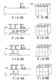
- Figs. 3A to 6B respectively show sequences of acquisition of MR signals (FID signals) Sig. by applying high-frequency fields RF and gradient fields G to four local areas A0 to A3 in a region of interest ROI (Figs. 3A, 4A, 5A, and 6A), and inverted and non-inverted states of the nuclear spin magnetization M of the local areas A0 to A3 (Figs. 3B, 4B, 5B, and 6B).
- "-1" and "1" respectively represent inverted and non-inverted states.
- a series of sequences of MR signal acquisition is constituted by four sequences in Figs. 3A, 4A, 5A, and 6A.
- the Hadamard matrix to which the inverted/non-inverted arrangement pattern of the local areas A0 to A3 is caused to correspond is of a fourth degree (4 ⁇ 4).
- selective inversion pulses I P (f2) and I P (f3) whose frequencies are respectively set to invert the magnetization of the local areas A2 and A3 corresponding to "-1" of the third row of the Hadamard matrix H are applied together with a gradient field pulse. Thereafter, a 90x° pulse is applied.
- selective inversion pulses I P (f1) and I P (f3) whose frequencies are respectively set to invert the magnetization of the local areas A1 and A3 corresponding to "-1" of the fourth row of the Hadamard matrix H are applied together with a gradient field pulse. Thereafter, a 90x° pulse is applied.
- MR signals are detected immediately after application of 90x° pulses without a dead time, and hence the signal of a nuclide having a short T2 can be obtained with little attenuation.
- An MR signal matrix S obtained by the series of sequences described above can be represented by the following equation:
- a selective inversion pulse has a sinc waveform which is normally used, and transverse magnetization is set to be zero by applying a spoiling gradient field pulse (see Figs. 4A, 5A, and 6A) upon application of a selective inversion pulse.
- the motion of each nuclear spin is calculated according to the Bloch equation.
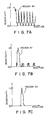
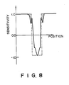
- Fig. 7A shows signal components included in the first column of the inverse Hadamard transform signal matrix D in equation (8). Ideally, these signal components are constituted by only components from the area A0. However, the selection characteristics, i.e., the sensitivity characteristics to positions, of a sinc waveform used as a selective inversion pulse is not represented by an ideal rectangular shape indicated by a broken line in Fig. 8 but is represented by a solid line in Fig. 8. As described above, since the selection characteristics of a selective inversion pulse are not sufficiently good, signal components from other areas A1, A2, ... are included.
- Fig. 7B shows signal components included in the second column of the MR signal matrix D. As shown in Fig. 7B, signal components from areas other than the area A1 are slightly included because of the influences of inverted magnetization of areas other than the area A1.
- an MR signal matrix (represented by SN) obtained by inverting the magnetization of local areas corresponding to "-1" of an Hadamard matrix using selective inversion pulses as shown in Figs. 9A to 12B is subtracted from the MR signal matrix (represented by SP) obtained by inverting the magnetization of the local areas corresponding to "-1" of the Hadamard matrix H as described with reference to Fig. 3A to 6B.
- Figs. 13A to 13C respectively show the detection sensitivities of MR signals detected from the areas A1, A2, and A3. Similar to Figs. 7A to 7C, Figs. 13A to 13C show the simulation results of detection sensitivities of MR signals. Figs. 13B and 13C show signal components from the areas A2 and A3 in which almost no signal component from other areas is included.
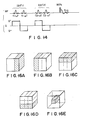
- Fig. 14 shows high-frequency fields and the application sequence of a gradient field in an MR apparatus according to a third embodiment of the present invention.
- a first selective excitation pulse having a frequency higher than a desired center frequency by a predetermined value and a second selective excitation pulse having a frequency lower than the center frequency by a predetermined value are used as selective inversion pulses.
- a selective inversion pulse Ip(f1) consists of a pair of selective excitation pulses respectively having frequencies of f1 + ⁇ f and f1 - ⁇ f.
- a gradient field G when the first excitation pulse is applied, for example, a positive gradient field pulse G+ is applied, whereas when the second excitation pulse is applied, a negative gradient field pulse G ⁇ is applied.
- Figs. 15A to 15C show the simulation results of detection sensitivities of MR signals from the three areas A1, A2, and A3 in this embodiment. It is apparent from Figs. 15A to 15C that detection sensitivity distributions in the respective areas are uniformed, and hence the selectivity is further improved. Note that the method for selective inversion shown in Fig. 14 can be combined with either of the methods of the two embodiments described above.
- the above-mentioned selective saturation pulse is, for example, a combination of a selective excitation pulse as a high-frequency field and a spoiling gradient field pulse for saturating magnetization excited by the selective excitation pulse.
Landscapes
- Physics & Mathematics (AREA)
- Spectroscopy & Molecular Physics (AREA)
- High Energy & Nuclear Physics (AREA)
- Condensed Matter Physics & Semiconductors (AREA)
- General Physics & Mathematics (AREA)
- Optics & Photonics (AREA)
- Engineering & Computer Science (AREA)
- Signal Processing (AREA)
- Magnetic Resonance Imaging Apparatus (AREA)
Abstract
Description
- The present invention relates to a magnetic resonance (MR) apparatus and, more particularly, to a magnetic resonance apparatus for obtaining the chemical shift information of a specific atomic nucleus in an object to be examined.
- As conventional methods of obtaining the chemical shift information of a specific nucleus in an object to be examined by utilizing a magnetic resonance method, localized spectroscopy (also called "one-point spectroscopy") disclosed in "BME Vol. 1, No. 3, pp. 169 - 180 and a chemical shift imaging method (also called "multi-point spectroscopy or phase encoding method") disclosed in "T.F. Budinger, Medical Magnetic Resonance Imaging and Spectroscopy, pp. 81 - 95, Society of Magnetic Resonance in Medicine, Berkely, Ca, 1986" and the like are known.
- Localized spectroscopy is a method of obtaining the chemical shift information of one local area, i.e., one point upon one measurement. In this method, therefore, it takes a long period of time to obtain chemical shift information of a large number of points. For this reason, this method is not suitable for a purpose of obtaining data of large number of points of normal and morbid portions and comparing the obtained data as in the field of clinical diagnoses in medical treatments.
- In contrast to this, according to the chemical shift imaging method, chemical information of a large number of points in a wide area can be imaged within a relatively short period of time. However, in the chemical shift imaging method, phase encoding for converting position information in an object to be examined into phase information of a (nuclear) magnetic resonance signal, i.e., an MR signal, is required in the course of acquisition of MR signal and an imaging process. For this reason, if a nuclide having a short T2 (transverse relaxation time) is processed, an MR signal is attenuated while the above phase encoding operation is performed, and an S/N (signal-to-noise ratio) of the MR signal or of chemical shift information obtained upon acquisition of the MR signal is decreased.
- As described above, the localized spectroscopy as one of the conventional methods for obtaining chemical shift information is not suitable for a clinical purpose because it requires a long period of time to obtain the chemical shift information of a large number of points. The chemical shift imaging method as another conventional method for obtaining chemical shift information requires an extra time for phase encoding in the course of acquisition of an MR signal and an imaging process. Hence, the chemical shift information of a nuclide having a short T2 cannot be extracted at a high S/N ratio.
- It is an object of the present invention to provide a magnetic resonance apparatus which can obtain the chemical shift information of a large number of points at once and which can obtain the chemical shift information of a nuclide having a short T2 at a high S/N ratio because phase encoding or the like is not required.
- A magnetic resonance apparatus according to a first aspect of the present invention acquires an MR signal matrix as follows. While a gradient field is applied to an object to be examined, a plurality of selective inversion pulses having different frequencies as high-frequency fields are sequentially applied to the object. Thereafter, a non-selective excitation pulse as a high-frequency field is applied to the object without application of a gradient field. In addition, an MR signal generated upon application of the non-selective excitation pulse is acquired. Such a series of sequences are repeated a plurality of times, while the frequencies of the selective inversion pulses are sequentially selected to cause a magnetization vector (to be simply referred to as "magnetization" hereinafter) of a nuclear spin of an area corresponding to either of "-1" and "1" of an Hadamard matrix to be inverted by each selective inversion pulse. Chemical shift information is obtained by transforming an MR signal matrix thus acquired in an aligning direction of the MR signal matrix by an inverse Hadamard transform, and transforming the transformed matrix in a time base direction by an inverse Fourier transform.
- A magnetic resonance apparatus according to a second aspect of the present invention comprises a first MR signal matrix acquiring section for repeating the same sequences as described above a plurality of times while sequentially changing the frequencies of selective inversion pulses so as to cause magnetization of areas corresponding to "-1" of an Hadamard matrix to be inverted by the respective selective inversion pulses, and a second MR signal matrix acquiring section for repeating the same sequences as described above a plurality of times while sequentially changing the frequencies of the selective inversion pulses so as to cause magnetization of areas corresponding to "1" of the Hadamard matrix to be inverted by the respective selective inversion pulses. A difference between MR signal matrices obtained by the first and second MR signal matrix acquiring sections is calculated. After a differential signal matrix based on the calculated difference is transformed in the aligning direction of the signal matrix by the inverse Hadamard transform, the transformed matrix is transformed in the time base direction by the inverse Fourier transform, thus obtaining chemical shift information.
- Each selective inversion pulse to be used in the above-described sequences may be a single pulse, but preferably consists of a first selective excitation pulse having a frequency higher than a desired center frequency by a predetermined value and a second selective excitation pulse having a frequency lower than the center frequency by a predetermined value. In this case, a gradient field consists of a pair of gradient field pulses having opposite polarities which are respectively used when the first and second selective excitation pulses are applied.
- In addition, according to the magnetic resonance apparatus of the present invention, selective excitation pulses for saturating the magnetization of areas other than an area of interest in an object to be examined from which magnetic resonance signals are acquired are preferably applied as high-frequency fields prior to execution of the above sequences, thereby performing three-dimensional positioning of the area of interest.
- In the apparatus of the present invention, an MR signal matrix can be obtained from a rod-like area of interest corresponding to an Hadamard matrix as a matrix transformed by Hadamard transform. If this matrix is transformed in the aligning direction of the matrix by inverse Hadamard transform, signals from local areas having volumes corresponding to the elements of the Hadamard matrix can be separately obtained. If the resultant values are transformed in the time base direction by the inverse Fourier transform, chemical shift information of each local area can be obtained.
- If the differential signal matrix based on the difference between the magnetic resonance signal matrices obtained by the first and second MR signal matrix acquiring sections is Hadamard-transformed, mixing of signals from the respective local areas with signals from other areas can be prevented, and area selectivity is improved.
- If a pair of first and second selective excitation pulses respectively having frequencies higher and lower than a desired center frequency by predetermined values are used as a selective inversion pulse, and gradient field pulses having opposite polarities are respectively used as gradient fields when the first and second excitation pulses are applied, disturbance of spin due to a gradient field can be canceled. As a result, the area selectivity of a selective inversion pulse can be improved, and the detection sensitivity of an MR signal can be increased.
- As described above, according to the apparatus of the present invention, MR signals from a plurality of local areas in a rod-like area of interest can be separately detected, and hence the chemical shift information of a large number of points can be obtained at once. Moreover, since phase encoding is not required, MR signals from the respective local areas can be separately obtained within a short period of time. Therefore, chemical shift information with a high S/N ratio can be obtained even from a nuclide having a short T2.
- According to the apparatus of the present invention, therefore, chemical shift information from a large number of points can be obtained at once without a dead time required for phase encoding. For this reason, chemical shift information with a high S/N ratio can be obtained from a nuclide having a short transverse relaxation time T2, e.g., an ATP (adenosine triphosphate) or Pi (inorganic phosphorus) component.
- This invention can be more fully understood from the following detailed description when taken in conjunction with the accompanying drawings, in which:
- Fig. 1 is a block diagram showing an arrangement of an MR apparatus according to a first embodiment of the present invention;
- Figs. 2A to 2C are views for explaining the principle of the first embodiment in Fig. 1;
- Figs. 3A to 6B are views for explaining a series of sequences of MR signal acquisition in the embodiment in Fig. 1;
- Figs. 7A to 7C are graphs showing simulation results of detection sensitivities of MR signals from the respective local areas in the sequences shown in Fig. 3A, 4A, 5A, and 6A;
- Fig. 8 is a graph showing ideal and actual characteristic curves of selection characteristics of a sinc waveform used as a selective inversion pulse;
- Figs. 9A to 12B are views for explaining a series of sequences of MR signal acquisition by an MR apparatus according to a second embodiment of the present invention;
- Figs. 13A to 13C are graphs showing simulating results of detection sensitivities of MR signals from the respective local areas in the sequences in Figs. 9A, 10A, 11A, and 12A;
- Fig. 14 is a graph for explaining a sequence of a high-frequency field and a gradient field for MR signal acquisition in an MR apparatus according to a third embodiment of the present invention;
- Figs. 15A to 15C are graphs showing simulation results of the detection sensitivities of MR signals from the respective local areas in the sequence in Fig. 14; and
- Figs. 16A to 16E are views showing a selective saturation process for three-dimensional positioning of a rod-like area of interest according to a fourth embodiment of the present invention.
- Fig. 1 shows an arrangement of an MR apparatus according to a first embodiment of the present invention. The apparatus shown in Fig. 1 is designed as an MR medical diagnosing apparatus.
- A
static field magnet 1 and agradient coil 3 are respectively driven by apower source 2 and a drive amplifier 4 so as to apply a uniform static field and a gradient field having a field intensity gradually changing in a predetermined direction onto anobject 5 to be examined (e.g., a human body, i.e., a patient) on a couch 6. Thepower source 2 and the drive amplifier 4 are controlled by asystem controller 10. - A high-frequency field is also applied from a probe 7 onto the
object 5. The high-frequency field is generated by the probe 7 on the basis of a high-frequency signal output from a transmittingsection 8 under the control of thesystem controller 10. In Fig. 1, the probe 7 is used as both a transmitting coil for generating a high-frequency field and a receiving coil for receiving an MR signal from theobject 5. However, transmitting and receiving coils may be independently arranged. - When nuclear spin, i.e., magnetization of a specific atomic nucleus in the
object 5 is excited by the high-frequency field, magnetic resonance occurs, and an MR signal based on the magnetic resonance is received by the probe 7. - The MR signal received by the probe 7 is amplified and detected by a receiving
section 9 and is supplied to a data sampling unit 11. Data transmission from the receivingsection 9 to the data sampling unit 11 is also performed under the control of thesystem controller 10. The data sampling unit 11 acquires the MR signal extracted by the receivingsection 9, and samples and converts it into a digital signal by using an A/D converter. Thereafter, the unit 11 supplies the digital signal to acomputer 12. The data sampling unit 11 is also operated under the control of thesystem controller 10. - The
computer 12 is operated in accordance with a command supplied from an operator through aconsole 13. Thecomputer 12 performs processing including an inverse Hadamard transform and an inverse Fourier transform of sampling data of an MR signal supplied from the data sampling unit 11 as will be described later, thereby obtaining the chemical shift information of an area of interest. In addition, thecomputer 12 controls thesystem controller 10. Chemical shift information obtained by thecomputer 12 is supplied to animage display 14 to be displayed. - A sequence for MR signal acquisition in the apparatus of this embodiment will be described with reference to Figs. 2 and 3.
- A magnetization vector ("magnetization") M of a nuclear spin in a static field is directed to the z′ direction of a rotating coordinate system (x′,y′,z′) rotating about the z-axis (i.e., to the z direction of an inertial coordinate system (x,y,z), as shown in Fig. 2A. If an inversion pulse (180° pulse) as a high-frequency field is applied to the above magnetization M, the magnetization M is rotated and directed to the -z direction, as shown in Fig. 2B.
- Upon application of a 90x° pulse directed to the x′ direction of the rotating coordinate system (x′,y′,z′), the magnetization M is rotated about the x′-axis and is directed to the "-1" direction in Fig. 2C. The magnetization M which receives no inversion pulse is rotated about the x′-axis and is directed to the "1" direction in Fig. 2C. Therefore, the sign of an MR signal to be observed at this time is changed depending on whether it is generated by nuclear spin upon application of an inversion pulse or by nuclear spin without application of an inversion pulse.
- Generally, an MR signal s(t) is given by the following equation:
s(t) = ∫∫∫∫ρ(x,y,z,ω)exp[jωt] ·exp[-t/T2(x,y,z,ω)]dxdydzdω (1)
ρ(x,y): nuclear spin density
ω: MR angular frequency
x,y,z: position
t: time - If a selective excitation pulse is used for a high-frequency field, only the magnetization M of nuclear spin of a specific local area can be inverted.
- An MR signal s(t) at this time can be represented by:
s(t) =sgn(i)∫∫∫∫Aiρ(x,y,z,ω)exp[jωt] ·exp[-t/T2(x,y,z,ω)]dxdydzdω (2)
Ai: local area
sgn(i): sign function (-1 is assigned when the magnetization M of the local area Ai is inverted; and 1, when it is not inverted) - In addition, if an MR signal from the local area Ai is represented by fi,
fi = ∫∫∫∫Aiρ(x,y,z,ω)exp[jωt] ·exp[-t/T2(x,y,z,ω)]dxdydzdω, and
s(t) =sgn(i)fi (3)
- In this case, assuming that the magnetization M of only a local area corresponding to "-1" of an Hadamard matrix of an area of interest in an object to be examined is inverted, the following equation can be obtained:
sj(t) =hij·fi (4)
hij: element of Hadamard matrix
- In this case, if an MR signal is observed while the value j is changed from 1 to n,
S = H·F
S: signal matrix

- In this case, if the signal matrix S is transformed by the inverse Hadamard transform,

- In this manner, a selective inversion pulse is applied to an area of interest such that the arrangement pattern of a local area whose magnetization M is inverted and a local area whose magnetization M is not inverted in the area of interest corresponds to the pattern of the Hadamard matrix H, and an MR signal matrix represented by equation (5) thus obtained is transformed by the Hadamard transform as represented by equation (6). As a result, separate MR signals can be obtained from the respective local areas. If the separate MR signal of each local area is transformed in the time base direction by the inverse Fourier transform, the MR spectrum (chemical shift information) of each local area can be obtained.
- Figs. 3A to 6B respectively show sequences of acquisition of MR signals (FID signals) Sig. by applying high-frequency fields RF and gradient fields G to four local areas A0 to A3 in a region of interest ROI (Figs. 3A, 4A, 5A, and 6A), and inverted and non-inverted states of the nuclear spin magnetization M of the local areas A0 to A3 (Figs. 3B, 4B, 5B, and 6B). Note that "-1" and "1" respectively represent inverted and non-inverted states. In this case, a series of sequences of MR signal acquisition is constituted by four sequences in Figs. 3A, 4A, 5A, and 6A. In this case, the Hadamard matrix to which the inverted/non-inverted arrangement pattern of the local areas A0 to A3 is caused to correspond is of a fourth degree (4 × 4).
- Since all the elements of the first row of this Hadamard matrix are "1", neither a selective inversion pulse as the high-frequency field RF nor the gradient field G are applied in the first sequence shown in Fig. 3A. In this case, since the magnetization of all the local areas A0 to A1 are not inverted, an FID signal Sig. = sl(t) obtained immediately after application of a 90x° pulse which is a non-selective excitation pulse as a high-frequency field is equivalent to the sum of signals from the respective local areas A0 to A3 as follows:
sl(t) = f0(t) + f1(t) + f2(t) + f3(t) - In the sequence shown in Fig. 4A, selective inversion pulses IP(f0) and IP(f3) whose frequencies are respectively set to invert the magnetization of the local areas A0 and A3 corresponding to "-1" of the second row of the Hadamard matrix H are applied together with a gradient field. Thereafter, a 90° pulse is applied. A signal Sig. = s2(t) obtained at this time is:
s2(t) = f0(t) - f1(t) + f2(t) - f3(t) - Similarly, in the sequence shown in Fig. 5A, selective inversion pulses IP(f2) and IP(f3) whose frequencies are respectively set to invert the magnetization of the local areas A2 and A3 corresponding to "-1" of the third row of the Hadamard matrix H are applied together with a gradient field pulse. Thereafter, a 90x° pulse is applied. In the sequence shown in Fig. 6A, selective inversion pulses IP(f1) and IP(f3) whose frequencies are respectively set to invert the magnetization of the local areas A1 and A3 corresponding to "-1" of the fourth row of the Hadamard matrix H are applied together with a gradient field pulse. Thereafter, a 90x° pulse is applied. In these sequences, the following signals are respectively obtained as a signal Sig. = s3(t) and a signal Sig. = s4(t):
s3(t) = f0(t) + f1(t) - f2(t) - f3(t) s4(t) = f0(t) - f1(t) - f2(t) + f3(t) - In the respective sequences shown in Figs. 3A, 4A, 5A, and 6A, MR signals are detected immediately after application of 90x° pulses without a dead time, and hence the signal of a nuclide having a short T2 can be obtained with little attenuation. An MR signal matrix S obtained by the series of sequences described above can be represented by the following equation:

- In this case, if this MR signal matrix is subjected to the inverse Hadamard transform, the following equation can be established, and the signals of the respective local areas A0 to A3 are independently obtained as follows:

- The detection sensitivities of MR signals detected from the three local areas A0, A1, and A2 of the eight local areas by using the sequences of MR signal acquisition described in the above embodiment are obtained by simulation. Figs. 7A to 7C show the results. In this case, a selective inversion pulse has a sinc waveform which is normally used, and transverse magnetization is set to be zero by applying a spoiling gradient field pulse (see Figs. 4A, 5A, and 6A) upon application of a selective inversion pulse. In addition, the motion of each nuclear spin is calculated according to the Bloch equation.
- Fig. 7A shows signal components included in the first column of the inverse Hadamard transform signal matrix D in equation (8). Ideally, these signal components are constituted by only components from the area A0. However, the selection characteristics, i.e., the sensitivity characteristics to positions, of a sinc waveform used as a selective inversion pulse is not represented by an ideal rectangular shape indicated by a broken line in Fig. 8 but is represented by a solid line in Fig. 8. As described above, since the selection characteristics of a selective inversion pulse are not sufficiently good, signal components from other areas A1, A2, ... are included. Fig. 7B shows signal components included in the second column of the MR signal matrix D. As shown in Fig. 7B, signal components from areas other than the area A1 are slightly included because of the influences of inverted magnetization of areas other than the area A1.
- An MR apparatus according to a second embodiment of the present invention will be described below. In this embodiment, an MR signal matrix (represented by SN) obtained by inverting the magnetization of local areas corresponding to "-1" of an Hadamard matrix using selective inversion pulses as shown in Figs. 9A to 12B is subtracted from the MR signal matrix (represented by SP) obtained by inverting the magnetization of the local areas corresponding to "-1" of the Hadamard matrix H as described with reference to Fig. 3A to 6B. Subsequently, the inverse Hadamard transform of an obtained differential signal matrix SP-SN is performed as in equation (9):
D = H⁻¹·S
= H⁻¹(SP - SN)
= DP - DN
where DP = H⁻¹·SP
DN = H⁻¹·SN (9) - In this case, the signs of signals from the areas A0 to A3 corresponding to DP and DN are opposite to each other, but the signs of signals from other areas are the same. For this reason, if DP - DN, signals from the areas A0 to A3 are respectively added to each other, and signals from other areas are subtracted from each other to become zero. According to this embodiment, therefore, selection characteristics with respect to the areas A0 to A3 are improved. Figs. 13A to 13C show selection characteristics with respect to the areas A1 to A3. Similar to the above-described case, the results obtained by the Hadamard transform are transformed by the inverse Fourier transform.
- Figs. 13A to 13C respectively show the detection sensitivities of MR signals detected from the areas A1, A2, and A3. Similar to Figs. 7A to 7C, Figs. 13A to 13C show the simulation results of detection sensitivities of MR signals. Figs. 13B and 13C show signal components from the areas A2 and A3 in which almost no signal component from other areas is included.
- Fig. 14 shows high-frequency fields and the application sequence of a gradient field in an MR apparatus according to a third embodiment of the present invention. In this system, a first selective excitation pulse having a frequency higher than a desired center frequency by a predetermined value and a second selective excitation pulse having a frequency lower than the center frequency by a predetermined value are used as selective inversion pulses. For example, a selective inversion pulse Ip(f1) consists of a pair of selective excitation pulses respectively having frequencies of f1 + Δf and f1 - Δf. With regard to a gradient field G, when the first excitation pulse is applied, for example, a positive gradient field pulse G⁺ is applied, whereas when the second excitation pulse is applied, a negative gradient field pulse G⁻ is applied.
- In this case, the magnetization of each local area is rotated through 90° twice, and hence is finally rotated through 180° (inverted). With this operation, disturbance of spin due to the gradient field is canceled, selectivity of a selective inversion pulse with respect to a local area can be further improved.
- Figs. 15A to 15C show the simulation results of detection sensitivities of MR signals from the three areas A1, A2, and A3 in this embodiment. It is apparent from Figs. 15A to 15C that detection sensitivity distributions in the respective areas are uniformed, and hence the selectivity is further improved. Note that the method for selective inversion shown in Fig. 14 can be combined with either of the methods of the two embodiments described above.
- In each embodiment described above, acquisition of MR signals from the rod-like area of interest is exemplified. In view of clinical treatments, however, this rod-like area of interest must be three-dimensionally positioned, and MR signals must be acquired from the three-dimensional area of interest. According to a fourth embodiment of the present invention, in order to satisfy such a requirement, spins in hatched areas shown in Figs. 16A to 16D are seemingly saturated by applying, e.g., selective saturation pulses so as to substantially cancel the magnetization of areas other than a hatched rod-like area (region of interest) shown in Fig. 16E, and the sequences described in each embodiment are performed. By performing such an operation for a plurality of rod-like areas of interest, MR signals can be acquired from a three-dimensional area of interest.
- The above-mentioned selective saturation pulse is, for example, a combination of a selective excitation pulse as a high-frequency field and a spoiling gradient field pulse for saturating magnetization excited by the selective excitation pulse.
Claims (7)
first signal acquiring means (1 - 4, 7 - 11) for obtaining a magnetic resonance signal matrix by repeating a series of sequences a plurality of times, the sequences including (a) applying a gradient field to an object to be examined which is placed in a uniform static field, and at the same time executing a selective inversion pulse application sequence for sequentially applying a plurality of selective inversion pulses having different frequencies as high-frequency fields onto the object, (b) applying a non-selective excitation pulse as a high-frequency field to the object without application of a gradient field, and (c) acquiring a magnetic resonance signal generated upon application of the non-selective excitation pulse, while the number and frequencies of selective inversion pulses are sequentially selected to cause a magnetization vector of a nuclear spin of an area corresponding to "-1" of an Hadamard matrix to be inverted by the selective inversion pulse application sequence;
second signal acquiring means (1 - 4, 7 - 11) for obtaining a magnetic resonance signal matrix by repeating the series of sequences while sequentially selecting the number and frequencies of selective inversion pulses so as to cause a magnetization vector of an area corresponding to "1" of the Hadamard matrix to be inverted by the selective inversion pulse application sequence; and
means (12) for obtaining chemical shift information by obtaining a differential signal matrix based on a difference between magnetic resonance matrices respectively obtained by said first and second signal acquiring means (1 - 4, 7 - 11), transforming the differential signal matrix in an aligning direction thereof by an inverse Hadamard transform, and transforming the transformed matrix in a time base direction by an inverse Fourier transform.
signal acquiring means (1 - 4, 7 - 11) for obtaining a magnetic resonance signal matrix by repeating a series of sequences a plurality of times, the sequences including (a) applying a gradient field to an object to be examined which is placed in a uniform static field, and at the same time executing a selective inversion pulse application sequence for sequentially applying a plurality of selective inversion pulses having different frequencies as high-frequency fields onto the object, each of the selective inversion pulses consisting of a pair of a first selective excitation pulse having a frequency higher than a desired center frequency by a predetermined value and a second selective excitation pulse having a frequency lower than the center frequency by a predetermined value, and the gradient field consisting of a pair of a first gradient field pulse having a predetermined polarity to be simultaneously applied with the first selective excitation pulse and a second gradient field having a polarity opposite to that of the first gradient field pulse, (b) applying a non-selective excitation pulse as a high-frequency field to the object without application of a gradient field, and (c) acquiring a magnetic resonance signal generated upon application of the non-selective excitation pulse, while the number and frequencies of selective inversion pulses are sequentially selected to cause a magnetization vector of a nuclear spin of an area corresponding to one of "-1" and "1" of an Hadamard matrix to be inverted by the selective inversion pulse application sequence; and
signal processing means (12) for obtaining chemical shift information by transforming the magnetic resonance signal matrix obtained by said signal acquiring means (1 - 4, 7 - 11) in an aligning direction of the magnetic resonance signal matrix by an inverse Hadamard transform, and transforming the transformed magnetic resonance signal matrix in a time base direction by an inverse Fourier transform.
saturating means (1 - 4, 7 - 11) for applying a selective saturation pulse to an object to be examined placed in a uniform static field so as to saturate magnetization of areas other than an area of interest in the object from which a magnetic resonance signal is to be acquired;
signal acquiring means (1 - 4, 7 - 11) for obtaining a magnetic resonance signal matrix by repeating a series of sequences a plurality of times, the sequences including (a) applying a gradient field to the object, and at the same time executing a selective inversion pulse application sequence for sequentially applying a plurality of selective inversion pulses having different frequencies as high-frequency fields onto the object, each of the selective inversion pulses consisting of a pair of a first selective excitation pulse having a frequency higher than a desired center frequency by a predetermined value and a second selective excitation pulse having a frequency lower than the center frequency by a predetermined value, and the gradient field consisting of a pair of a first gradient field pulse having a predetermined polarity to be simultaneously applied with the first selective excitation pulse and a second gradient field having a polarity opposite to that of the first gradient field pulse, (b) applying a non-selective excitation pulse as a high-frequency field to the object without application of a gradient field, and (c) acquiring a magnetic resonance signal generated upon application of the non-selective excitation pulse, while the number and frequencies of selective inversion pulses are sequentially selected to cause a magnetization vector of a nuclear spin of an area corresponding to one of "-1" and "1" of an Hadamard matrix to be inverted by the selective inversion pu|se application sequence; and
signal processing means (12) for obtaining chemical shift information by transforming the magnetic resonance signal matrix obtained by said signal acquiring means (1 - 4, 7 - 11) in an aligning direction of the magnetic resonance signal matrix by an inverse Hadamard transform, and transforming the transformed magnetic resonance signal matrix in a time base direction by an inverse Fourier transform.
Applications Claiming Priority (2)
| Application Number | Priority Date | Filing Date | Title |
|---|---|---|---|
| JP246456/88 | 1988-09-30 | ||
| JP63246456A JP2731178B2 (en) | 1988-09-30 | 1988-09-30 | Magnetic resonance diagnostic equipment |
Publications (3)
| Publication Number | Publication Date |
|---|---|
| EP0361671A2 true EP0361671A2 (en) | 1990-04-04 |
| EP0361671A3 EP0361671A3 (en) | 1991-07-03 |
| EP0361671B1 EP0361671B1 (en) | 1997-01-02 |
Family
ID=17148699
Family Applications (1)
| Application Number | Title | Priority Date | Filing Date |
|---|---|---|---|
| EP89308417A Expired - Lifetime EP0361671B1 (en) | 1988-09-30 | 1989-08-18 | Magnetic resonance apparatus |
Country Status (4)
| Country | Link |
|---|---|
| US (1) | US4959610A (en) |
| EP (1) | EP0361671B1 (en) |
| JP (1) | JP2731178B2 (en) |
| DE (1) | DE68927602T2 (en) |
Cited By (1)
| Publication number | Priority date | Publication date | Assignee | Title |
|---|---|---|---|---|
| EP0774672A1 (en) * | 1995-11-18 | 1997-05-21 | Philips Patentverwaltung GmbH | Method for determining the spatial and/or spectral distribution of nuclear magnetization |
Families Citing this family (4)
| Publication number | Priority date | Publication date | Assignee | Title |
|---|---|---|---|---|
| US5787886A (en) * | 1993-03-19 | 1998-08-04 | Compass International Incorporated | Magnetic field digitizer for stereotatic surgery |
| US5422572A (en) * | 1993-08-06 | 1995-06-06 | Toshiba America Mri, Inc. | Method and apparatus for substantially simultaneously exciting a plurality of slices in NMR imaging |
| US9398242B2 (en) * | 2008-11-17 | 2016-07-19 | Universal Electronics Inc. | System and method for rapid configuration of a universal controlling device |
| US8965094B2 (en) * | 2012-04-14 | 2015-02-24 | Nocimed, Llc | Magnetic resonance spectroscopy pulse sequence, acquisition, and processing system and method |
Family Cites Families (2)
| Publication number | Priority date | Publication date | Assignee | Title |
|---|---|---|---|---|
| US4689567A (en) * | 1984-06-01 | 1987-08-25 | Advanced Nmr Systems, Inc. | NMR Fourier imaging from multiple echoes |
| US4609872A (en) * | 1984-08-10 | 1986-09-02 | General Electric Company | NMR multiple-echo phase-contrast blood flow imaging |
-
1988
- 1988-09-30 JP JP63246456A patent/JP2731178B2/en not_active Expired - Lifetime
-
1989
- 1989-08-16 US US07/394,675 patent/US4959610A/en not_active Expired - Lifetime
- 1989-08-18 EP EP89308417A patent/EP0361671B1/en not_active Expired - Lifetime
- 1989-08-18 DE DE68927602T patent/DE68927602T2/en not_active Expired - Fee Related
Non-Patent Citations (2)
| Title |
|---|
| SOCIETE OF MAGNETIC RESONANCE IN MEDICINE, 7TH ANNUAL MEETING, San Francisco, CA, 20th - 26th August 1988, Book of Abstracts, vol.2, page 953; Y. SUZUKI et al.: "New spectroscopy method using Hamamard matrix selective 180 degree RF pulses" * |
| SOCIETY OF MAGNETIC RESONANCE IN MEDICINE, 7TH ANNUAL MEETING, San Francisco, CA, 20th - 26th August 1988, Book of Abstracts, vol. 2, page 750; L. BOLINGER et al.: "Hamamard spectroscopic imaging for multi-volume localization" * |
Cited By (1)
| Publication number | Priority date | Publication date | Assignee | Title |
|---|---|---|---|---|
| EP0774672A1 (en) * | 1995-11-18 | 1997-05-21 | Philips Patentverwaltung GmbH | Method for determining the spatial and/or spectral distribution of nuclear magnetization |
Also Published As
| Publication number | Publication date |
|---|---|
| EP0361671A3 (en) | 1991-07-03 |
| DE68927602T2 (en) | 1997-07-17 |
| JPH02224640A (en) | 1990-09-06 |
| US4959610A (en) | 1990-09-25 |
| JP2731178B2 (en) | 1998-03-25 |
| DE68927602D1 (en) | 1997-02-13 |
| EP0361671B1 (en) | 1997-01-02 |
Similar Documents
| Publication | Publication Date | Title |
|---|---|---|
| WO1994003822A1 (en) | Methods and apparatus for mri | |
| US4528509A (en) | Spatially selective NMR | |
| EP0112663B1 (en) | Nuclear magnetic resonance methods and apparatus | |
| US5912557A (en) | Centric phase encoding order for 3D NMR data acquisition | |
| US4654591A (en) | NMR flow imaging using bi-phasic excitation field gradients | |
| EP0165610B1 (en) | High speed imaging method with three-dimensional nmr | |
| EP0527462B1 (en) | Magnetic resonance imaging method and system capable of measuring short "T2" signal components | |
| US6154029A (en) | MR imaging method and apparatus | |
| EP0361671B1 (en) | Magnetic resonance apparatus | |
| JPH0357774B2 (en) | ||
| US4646023A (en) | Nuclear magnetic resonance imaging | |
| US5635837A (en) | MR method utilizing inductively coupled receiving coil systems | |
| US4801884A (en) | Apparatus for the identification of nuclear magnetic spectra from spatially selectable regions of an examination subject | |
| EP0135143B1 (en) | Imaging method and apparatus using nuclear magnetic resonance | |
| EP0128622A1 (en) | Method of and device for determining a nuclear magnetization distribution in a region of a body | |
| GB2105853A (en) | Spatially selective NMR | |
| JP3452400B2 (en) | Magnetic resonance imaging equipment | |
| EP0246327A1 (en) | Method and apparatus for nmr imaging | |
| JPH0751124B2 (en) | NMR inspection device using chemical shift value | |
| JPS63194646A (en) | Magnetic resonace tomographic imaging examination method and apparatus | |
| US5113138A (en) | Carbon mr spectroscopy method and device for performing the method | |
| JPH06169A (en) | Method and device for measuring diffusion by mr | |
| EP0109517B1 (en) | Nuclear magnetic resonance diagnostic apparatus | |
| JPS60201242A (en) | NMR tomography device | |
| EP0390176A2 (en) | Testing method and apparatus by use of NMR |
Legal Events
| Date | Code | Title | Description |
|---|---|---|---|
| PUAI | Public reference made under article 153(3) epc to a published international application that has entered the european phase |
Free format text: ORIGINAL CODE: 0009012 |
|
| 17P | Request for examination filed |
Effective date: 19890908 |
|
| AK | Designated contracting states |
Kind code of ref document: A2 Designated state(s): DE GB |
|
| PUAL | Search report despatched |
Free format text: ORIGINAL CODE: 0009013 |
|
| AK | Designated contracting states |
Kind code of ref document: A3 Designated state(s): DE GB |
|
| 17Q | First examination report despatched |
Effective date: 19940519 |
|
| GRAH | Despatch of communication of intention to grant a patent |
Free format text: ORIGINAL CODE: EPIDOS IGRA |
|
| GRAH | Despatch of communication of intention to grant a patent |
Free format text: ORIGINAL CODE: EPIDOS IGRA |
|
| GRAA | (expected) grant |
Free format text: ORIGINAL CODE: 0009210 |
|
| AK | Designated contracting states |
Kind code of ref document: B1 Designated state(s): DE GB |
|
| REF | Corresponds to: |
Ref document number: 68927602 Country of ref document: DE Date of ref document: 19970213 |
|
| PLBE | No opposition filed within time limit |
Free format text: ORIGINAL CODE: 0009261 |
|
| STAA | Information on the status of an ep patent application or granted ep patent |
Free format text: STATUS: NO OPPOSITION FILED WITHIN TIME LIMIT |
|
| 26N | No opposition filed | ||
| REG | Reference to a national code |
Ref country code: GB Ref legal event code: 746 Effective date: 19981023 |
|
| PGFP | Annual fee paid to national office [announced via postgrant information from national office to epo] |
Ref country code: DE Payment date: 20010813 Year of fee payment: 13 |
|
| PGFP | Annual fee paid to national office [announced via postgrant information from national office to epo] |
Ref country code: GB Payment date: 20010815 Year of fee payment: 13 |
|
| REG | Reference to a national code |
Ref country code: GB Ref legal event code: IF02 |
|
| PG25 | Lapsed in a contracting state [announced via postgrant information from national office to epo] |
Ref country code: GB Free format text: LAPSE BECAUSE OF NON-PAYMENT OF DUE FEES Effective date: 20020818 |
|
| PG25 | Lapsed in a contracting state [announced via postgrant information from national office to epo] |
Ref country code: DE Free format text: LAPSE BECAUSE OF NON-PAYMENT OF DUE FEES Effective date: 20030301 |
|
| GBPC | Gb: european patent ceased through non-payment of renewal fee |
Effective date: 20020818 |