EP0361683B1 - Verfahren zur Datenübertragung zwischen Speichern - Google Patents
Verfahren zur Datenübertragung zwischen Speichern Download PDFInfo
- Publication number
- EP0361683B1 EP0361683B1 EP89308699A EP89308699A EP0361683B1 EP 0361683 B1 EP0361683 B1 EP 0361683B1 EP 89308699 A EP89308699 A EP 89308699A EP 89308699 A EP89308699 A EP 89308699A EP 0361683 B1 EP0361683 B1 EP 0361683B1
- Authority
- EP
- European Patent Office
- Prior art keywords
- data
- block
- location
- stored
- memory means
- Prior art date
- Legal status (The legal status is an assumption and is not a legal conclusion. Google has not performed a legal analysis and makes no representation as to the accuracy of the status listed.)
- Expired - Lifetime
Links
Images



Classifications
-
- G—PHYSICS
- G06—COMPUTING OR CALCULATING; COUNTING
- G06F—ELECTRIC DIGITAL DATA PROCESSING
- G06F11/00—Error detection; Error correction; Monitoring
- G06F11/07—Responding to the occurrence of a fault, e.g. fault tolerance
- G06F11/16—Error detection or correction of the data by redundancy in hardware
- G06F11/20—Error detection or correction of the data by redundancy in hardware using active fault-masking, e.g. by switching out faulty elements or by switching in spare elements
- G06F11/2053—Error detection or correction of the data by redundancy in hardware using active fault-masking, e.g. by switching out faulty elements or by switching in spare elements where persistent mass storage functionality or persistent mass storage control functionality is redundant
- G06F11/2056—Error detection or correction of the data by redundancy in hardware using active fault-masking, e.g. by switching out faulty elements or by switching in spare elements where persistent mass storage functionality or persistent mass storage control functionality is redundant by mirroring
- G06F11/2071—Error detection or correction of the data by redundancy in hardware using active fault-masking, e.g. by switching out faulty elements or by switching in spare elements where persistent mass storage functionality or persistent mass storage control functionality is redundant by mirroring using a plurality of controllers
-
- G—PHYSICS
- G06—COMPUTING OR CALCULATING; COUNTING
- G06F—ELECTRIC DIGITAL DATA PROCESSING
- G06F3/00—Input arrangements for transferring data to be processed into a form capable of being handled by the computer; Output arrangements for transferring data from processing unit to output unit, e.g. interface arrangements
- G06F3/06—Digital input from, or digital output to, record carriers, e.g. RAID, emulated record carriers or networked record carriers
- G06F3/0601—Interfaces specially adapted for storage systems
- G06F3/0628—Interfaces specially adapted for storage systems making use of a particular technique
- G06F3/0638—Organizing or formatting or addressing of data
- G06F3/0644—Management of space entities, e.g. partitions, extents, pools
-
- G—PHYSICS
- G06—COMPUTING OR CALCULATING; COUNTING
- G06F—ELECTRIC DIGITAL DATA PROCESSING
- G06F11/00—Error detection; Error correction; Monitoring
- G06F11/07—Responding to the occurrence of a fault, e.g. fault tolerance
- G06F11/14—Error detection or correction of the data by redundancy in operations
- G06F11/1446—Point-in-time backing up or restoration of persistent data
- G06F11/1448—Management of the data involved in backup or backup restore
- G06F11/1451—Management of the data involved in backup or backup restore by selection of backup contents
-
- G—PHYSICS
- G06—COMPUTING OR CALCULATING; COUNTING
- G06F—ELECTRIC DIGITAL DATA PROCESSING
- G06F3/00—Input arrangements for transferring data to be processed into a form capable of being handled by the computer; Output arrangements for transferring data from processing unit to output unit, e.g. interface arrangements
- G06F3/06—Digital input from, or digital output to, record carriers, e.g. RAID, emulated record carriers or networked record carriers
- G06F3/0601—Interfaces specially adapted for storage systems
-
- G—PHYSICS
- G06—COMPUTING OR CALCULATING; COUNTING
- G06F—ELECTRIC DIGITAL DATA PROCESSING
- G06F3/00—Input arrangements for transferring data to be processed into a form capable of being handled by the computer; Output arrangements for transferring data from processing unit to output unit, e.g. interface arrangements
- G06F3/06—Digital input from, or digital output to, record carriers, e.g. RAID, emulated record carriers or networked record carriers
- G06F3/0601—Interfaces specially adapted for storage systems
- G06F3/0602—Interfaces specially adapted for storage systems specifically adapted to achieve a particular effect
- G06F3/061—Improving I/O performance
- G06F3/0611—Improving I/O performance in relation to response time
-
- G—PHYSICS
- G06—COMPUTING OR CALCULATING; COUNTING
- G06F—ELECTRIC DIGITAL DATA PROCESSING
- G06F3/00—Input arrangements for transferring data to be processed into a form capable of being handled by the computer; Output arrangements for transferring data from processing unit to output unit, e.g. interface arrangements
- G06F3/06—Digital input from, or digital output to, record carriers, e.g. RAID, emulated record carriers or networked record carriers
- G06F3/0601—Interfaces specially adapted for storage systems
- G06F3/0628—Interfaces specially adapted for storage systems making use of a particular technique
- G06F3/0638—Organizing or formatting or addressing of data
- G06F3/064—Management of blocks
-
- G—PHYSICS
- G06—COMPUTING OR CALCULATING; COUNTING
- G06F—ELECTRIC DIGITAL DATA PROCESSING
- G06F3/00—Input arrangements for transferring data to be processed into a form capable of being handled by the computer; Output arrangements for transferring data from processing unit to output unit, e.g. interface arrangements
- G06F3/06—Digital input from, or digital output to, record carriers, e.g. RAID, emulated record carriers or networked record carriers
- G06F3/0601—Interfaces specially adapted for storage systems
- G06F3/0628—Interfaces specially adapted for storage systems making use of a particular technique
- G06F3/0646—Horizontal data movement in storage systems, i.e. moving data in between storage devices or systems
-
- G—PHYSICS
- G06—COMPUTING OR CALCULATING; COUNTING
- G06F—ELECTRIC DIGITAL DATA PROCESSING
- G06F3/00—Input arrangements for transferring data to be processed into a form capable of being handled by the computer; Output arrangements for transferring data from processing unit to output unit, e.g. interface arrangements
- G06F3/06—Digital input from, or digital output to, record carriers, e.g. RAID, emulated record carriers or networked record carriers
- G06F3/0601—Interfaces specially adapted for storage systems
- G06F3/0668—Interfaces specially adapted for storage systems adopting a particular infrastructure
- G06F3/0671—In-line storage system
- G06F3/0673—Single storage device
- G06F3/0674—Disk device
Definitions
- This invention relates to a method for transferring a data base from a first memory means to a second memory means.
- a backup system has been utilized to ensure that no data is lost when the primary terminal device becomes disabled.
- the backup system includes a second primary terminal device which receives the same data as the first primary terminal device during a merchandising operation. When the second primary terminal device becomes disabled or is withdrawn from operation, the data stored in the first primary terminal device is required to be downloaded to the second primary terminal device at the conclusion of a day's operation so as to update the data in the second primary terminal device.
- FIG. 1 there is shown a schematic block diagram of the first and second primary terminal devices indicated by numerals 20 and 22 arranged for a downloading operation.
- Each of the terminal devices 20, 22 includes an operating system 23, a processor 24, a disk file 26 and a plurality of disk drivers 28 for writing and reading data in the disk file and a communication controller 30 for controlling the transfer of data over a communication bus 32 coupled between the terminal devices 20 and 22.
- the basic storage area in the disk file is a block of data 34 which comprises a maximum of 256 bytes of data.
- Four blocks of data comprise one granule containing a maximum of 1024 bytes of data.
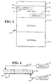
- FIG. 3 there is shown a schematic diagram of the disk file 26 (Fig. 1) in which the file of the present embodiment is divided into a number of partitions 40-1 to 40-N inclusive.
- the first row of data 38 of the disk file 26 contains thirty-three blocks of data comprising a directory in which the data represents the location of a first or begin block 42 and a last or end block 44, which blocks define the allocated disk space in each of the partitions 40-1 to 40-N in which data may be stored.
- the end block 44 in each of the partitions 40-1 to 40-N inclusive may be located at any position in the partition depending on the desired amount of data to be stored therein.
- the disk file 26 (Fig. 1) in which the file of the present embodiment is divided into a number of partitions 40-1 to 40-N inclusive.
- each of the terminals may contain up to four partitions 40-1 to 40-N inclusive.
- the begin block 42 for each partition contains data representing the number of freespace maps that are located in the begin block.
- a freespace map locates the number of granules of data in the partition which have valid data stored therein.
- FIG. 4 there is illustrated a diagrammatic representation of an eight bit portion 46 of a freespace map 62 (Fig. 6) located in the begin block 42 (Fig. 3) of each partition in which each bit in the map indicates whether or not valid data is contained in a corresponding granule of data.
- Each bit of the freespace map 46 may contain a binary one comprising a flag which represents that a corresponding granule of data in the partition contains valid data that is to be transferred.
- the first bit 48 in the freespace map 46 represents the storage condition of a corresponding granule 52 of data, as indicated by the line 50.
- the granule 52 is allocated by the operating system 23 (Fig.
- the flag bit is set by the system 23 to one in block 48 of the freespace map 46.
- the portion 46 contains the hexadecimal data F8 (Fig. 6)
- the blocks 48 would contain the binary bits illustrated.
- the eighth block 54 represents the storage condition of the number eight granule 58, as indicated by the line 56, and is set to a binary zero, representing that no valid data is stored in granule 58.
- the first row in the directory block contains hexadecimal data at locations 05-0C inclusive which indicates, according to a predetermined code, that this information relates to the first partition 40-1 (Fig. 3).
- the hexadecimal data F0, F0, F0, F3 and F3 located therein indicates that the begin block of partition 40-1 is block 33.
- the hexadecimal data F0, F2, F5, F6 and F1 in locations 22-26 inclusive, in the third row represent the location of the end block of the partition, which in the present embodiment is 2561.
- the partition 40-1 is indicated as having up to 2528 blocks of allocated data space, of which only the valid data contained therein is to be transferred.
- Fig. 6 there is shown the begin block 33 referred to in the description of Fig. 5, in partition 40-1.
- the hexadecimal signal 01 found at location 00 indicates that there is one freespace map for this partition.
- Each freespace map represents up to one megabyte of data.
- the freespace map indicated by the reference character 62 includes the digits 00 when no valid data is stored in the corresponding granules of data and includes hexadecimal data such as F8 (Fig. 4) which represents the granules having valid data stored therein.
- the freespace map starts at location 80 and extends through location CE, allowing the map to cover 632 granules of disk space.
- Each partition may contain more than one freespace map, depending on the amount of data stored on the disk file.
- a flag bit is set to 1 in the byte of the freespace map corresponding to that location in the physical disk layout, indicating an allocated granule.
- searching backwards from location CE at the end of the map it will be found, in the present example, that the first non-zero byte F8 is at location 80, indicating the location of blocks of disk space that contain valid data.
- FIG. 7 there is shown a flow chart of an overall view of a downloading operation which begins (block 66) by the processor 24 in terminal device 20 determining the begin block and the end block of each disk partition (block 68) in the disk file 26 by reading the information in the directory row 38 of the disk file 26 (Figs. 3 and 5) and then reading the freespace maps in the begin block to determine the location of the valid data in the partition.
- the processor 24 in the first primary terminal device 20 will enable the drivers 28 to transfer the valid data in each of the partitions by reading the data block by block from the primary disk file 26 to the other primary disk file 26 in the second primary terminal device 22 (block 70).
- the processor 24 in terminal device 20 will detect if another partition is to be transferred (block 72). If it is, the processor will return over line 77 to block 68 until all of the valid data in each of the partitions has been transferred. This processor will then disable the drivers (block 74) to complete (block 76) the transfer operation.
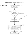
- Figs. 8A and 8B there is shown a flow chart of the operation for determining the begin block and the end block of the valid data in each of the partitions.
- the processor 24 in terminal device 20 (Fig. 1) will start the operation (block 78) by determining the location of the begin block and the end block for each partition (block 80) by reading the blocks of data in the directory row 38 of the disk file 26 (Fig. 3). After detecting the location of the begin block in a partition, the processor will read the begin block (Fig. 6) to determine the number of freespace maps in the partition (block 82). The processor will then read the last freespace map (block 84) byte-by-byte for a flag indicating an allocated granule (Fig.
- the processor will then determine if the freespace map is associated with the first partition (block 96) and if it is, it will then set the begin block to the first block in row 1 of the disk file (block 98) which is the directory row 38 of the disk file (Fig. 3) which directory row is transferred with the valid data.
- the processor will then set the end block equal to the begin block plus the number of allocated blocks (block 100) and then return to its original position (block 102). If the partition to be copied is not the first partition, the system will go over line 101, bypassing the step of setting the begin block to the first block of the directory row of the disk file 26.
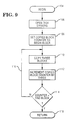
- FIG. 9 there is shown a flow chart of the downloading process in which the processor 24 of terminal device 20 will begin (block 104) by opening or operating the disk drivers 28 (Fig. 1) (block 106) for each of the partitions 40 (Fig. 3) and then set a counter (not shown) located in the disk file to the begin block (108) location.
- the processor will then copy three blocks of valid data (block 110) since this has been found to be the optimum transfer rate of the communication system.
- the processor increments the counter by three (block 112) and then checks to see if the output count of the counter is greater than the end block number (block 114). If it is not, it will then return over line 116 and copy the next three blocks (block 110) of data. If the count is greater than the number associated with the end block, the processor will return to its initial operating position (block 118).
Landscapes
- Engineering & Computer Science (AREA)
- Theoretical Computer Science (AREA)
- Physics & Mathematics (AREA)
- General Engineering & Computer Science (AREA)
- General Physics & Mathematics (AREA)
- Human Computer Interaction (AREA)
- Quality & Reliability (AREA)
- Information Retrieval, Db Structures And Fs Structures Therefor (AREA)
- Computer And Data Communications (AREA)
Claims (2)
- Verfahren zum Übertragen von Daten von einer ersten Speichereinrichtung (26 in 20) zu einer zweiten Speichereinrichtung (26 in 22) in einer Vorrichtung, die die erste Speichereinrichtung (26 in 20) und die zweite Speichereinrichtung (26 in 22) umfaßt, wobei die erste Speichereinrichtung (26 in 20) in eine Vielzahl definierter Speicherbereiche (40-1 bis 40-N) unterteilt ist, von denen jeder eine Vielzahl von Datenplatzblöcken enthält; wobei eine erste Datenplatzreihe (38) der ersten Speichereinrichtung (26 in 20) vorgesehen ist, um eine Vielzahl erster Datenbitsätze zu speichern, welche die Lage des ersten Blocks (42) und des letzten Blocks (44) des Datenplatzes in allen definierten Speicherbereichen (40-1 bis 40-N) liefern, die den vorgesehenen Speicherplatz anzeigen, in dem Daten gespeichert sind; wobei jeder dieser definierten Speicherbereiche (40-1 bis 40-N) ausgelegt ist, um wenigstens einen zweiten Datenbitsatz (62) zu speichern, der die Lage der in diesem vorgesehenen Speicherplatz gespeicherten gültigen und ungültigen Daten erkennt; und wobei alle zweiten Datenbitsätze (62) eine erste Art binärer Bits enthalten, die anzeigen, daß gültige Daten in korrespondierenden Blockgruppen des zugeordneten definierten Speicherbereiches (40-1 bis 40-N) gespeichert sind, und eine zweite Art binärer Bits, die anzeigen, daß ungültige Daten in korrespondierenden Blockgruppen des zugeordneten definierten Speicherbereiches (40-1 bis 40-N) gespeichert sind,
gekennzeichnet durch
die Schritte des Aufsuchens der zweiten Datenbits (62) in Reihenfolge in einer vorbestimmten Richtung, um die Lage des während dieser Suche gefundenen ersten binären Bits der ersten Art zu bestimmen; diese Lage zu benutzen, um eine Anzahl von Datenblöcken zu bestimmen, die auf die zweite Speichereinrichtung (26 in 20) übertragen werden sollen; und Übertragen der bestimmten Datenblockanzahl zu der zweiten Speichereinrichtung (26 in 22). - Verfahren nach Anspruch 1, wobei dritte Datenbits in dem ersten Datenplatzblock (42) in jedem der definierten Speicherbereiche (40-1 bis 40-N) gespeichert sind, die die Anzahl der zweiten Datenbitsätze (62) anzeigen, die in den zugeordneten definierten Speicherbereichen (40-1 bis 40-N) gespeichert sind, dadurch gekennzeichnet, daß der Schritt des Aufsuchens den Schritt umfaßt, daß zuerst der letzte der zweiten Datenbitsätze (62) aufgesucht wird.
Applications Claiming Priority (2)
| Application Number | Priority Date | Filing Date | Title |
|---|---|---|---|
| US23864188A | 1988-08-30 | 1988-08-30 | |
| US238641 | 1988-08-30 |
Publications (3)
| Publication Number | Publication Date |
|---|---|
| EP0361683A2 EP0361683A2 (de) | 1990-04-04 |
| EP0361683A3 EP0361683A3 (de) | 1991-07-24 |
| EP0361683B1 true EP0361683B1 (de) | 1995-06-14 |
Family
ID=22898725
Family Applications (1)
| Application Number | Title | Priority Date | Filing Date |
|---|---|---|---|
| EP89308699A Expired - Lifetime EP0361683B1 (de) | 1988-08-30 | 1989-08-29 | Verfahren zur Datenübertragung zwischen Speichern |
Country Status (3)
| Country | Link |
|---|---|
| EP (1) | EP0361683B1 (de) |
| JP (1) | JP2761937B2 (de) |
| DE (1) | DE68923044T2 (de) |
Families Citing this family (3)
| Publication number | Priority date | Publication date | Assignee | Title |
|---|---|---|---|---|
| JP3183719B2 (ja) * | 1992-08-26 | 2001-07-09 | 三菱電機株式会社 | アレイ型記録装置 |
| US6038639A (en) * | 1997-09-09 | 2000-03-14 | Storage Technology Corporation | Data file storage management system for snapshot copy operations |
| GB2353611B (en) | 1999-08-24 | 2004-03-17 | Ibm | Disk image backup/restore with data preparation phase |
-
1989
- 1989-08-29 JP JP1220518A patent/JP2761937B2/ja not_active Expired - Lifetime
- 1989-08-29 EP EP89308699A patent/EP0361683B1/de not_active Expired - Lifetime
- 1989-08-29 DE DE68923044T patent/DE68923044T2/de not_active Expired - Fee Related
Also Published As
| Publication number | Publication date |
|---|---|
| EP0361683A2 (de) | 1990-04-04 |
| JP2761937B2 (ja) | 1998-06-04 |
| EP0361683A3 (de) | 1991-07-24 |
| DE68923044T2 (de) | 1996-02-22 |
| JPH02120945A (ja) | 1990-05-08 |
| DE68923044D1 (de) | 1995-07-20 |
Similar Documents
| Publication | Publication Date | Title |
|---|---|---|
| US5109485A (en) | Method for transferring data between memories | |
| US5568626A (en) | Method and system for rewriting data in a non-volatile memory a predetermined large number of times | |
| US5566314A (en) | Flash memory device employing unused cell arrays to update files | |
| US5586247A (en) | Data updating system capable of partially recovering data | |
| EP0280795B1 (de) | Verfahren und Einrichtung zur Speicherung einer haufenweise unterteilten Binaerdatenbasis | |
| CN1926616B (zh) | 使用存储器地址映射表的便携式数据存储设备 | |
| EP0375188A2 (de) | Dateisystem | |
| MY121756A (en) | External storage apparatus and data processing method | |
| CA1123361A (en) | Text processing apparatus | |
| EP0615193A1 (de) | Speicherkartenvorrichtung. | |
| US4027288A (en) | Self-managing variable field storage system for handling nested data structures | |
| US4685057A (en) | Memory mapping system | |
| EP0361683B1 (de) | Verfahren zur Datenübertragung zwischen Speichern | |
| EP0200440B1 (de) | Elektronische Schaltung zur Verbindung eines Prozessors mit einem leistungsfähigen Speicher | |
| EP1540660B1 (de) | Verfahren und vorrichtung zur erkennung von fehlern während des schreibens in einen nichtflüchtigen speicher | |
| US4642793A (en) | Many-to-one mapping hash address generator | |
| US5568634A (en) | Method of writing in a non-volatile memory, notably in a memory card employing memory allocation strategies on size and occupancy basis | |
| EP0319147A3 (de) | Verfahren zur Speicherung von Dateien von vorstrukturierten Gruppen verbundener Informationen in einem Datenverarbeitungssystem | |
| EP0740259A2 (de) | Speicherzuordnung in einem Steuergerät für Fahrzeuge | |
| US4249250A (en) | Computer storage arrangements with overwrite warning | |
| JP2661131B2 (ja) | 情報記憶読出方法とその装置 | |
| US3597745A (en) | Method for arrangement and indexing of digital data in storage | |
| EP0522728B1 (de) | Verfahren zum effizienten Zugriff von Daten in einer Verknüpfungstabelle | |
| GB2106290A (en) | Electronic equipment with character memory | |
| WO1996005703A3 (en) | Method for transfer of data files from a mass storage device to a post-processing system |
Legal Events
| Date | Code | Title | Description |
|---|---|---|---|
| PUAI | Public reference made under article 153(3) epc to a published international application that has entered the european phase |
Free format text: ORIGINAL CODE: 0009012 |
|
| AK | Designated contracting states |
Kind code of ref document: A2 Designated state(s): DE FR GB |
|
| PUAL | Search report despatched |
Free format text: ORIGINAL CODE: 0009013 |
|
| AK | Designated contracting states |
Kind code of ref document: A3 Designated state(s): DE FR GB |
|
| 17P | Request for examination filed |
Effective date: 19920109 |
|
| 17Q | First examination report despatched |
Effective date: 19940302 |
|
| RAP1 | Party data changed (applicant data changed or rights of an application transferred) |
Owner name: NCR INTERNATIONAL INC. |
|
| RAP1 | Party data changed (applicant data changed or rights of an application transferred) |
Owner name: AT&T GLOBAL INFORMATION SOLUTIONS INTERNATIONAL IN |
|
| GRAA | (expected) grant |
Free format text: ORIGINAL CODE: 0009210 |
|
| AK | Designated contracting states |
Kind code of ref document: B1 Designated state(s): DE FR GB |
|
| REF | Corresponds to: |
Ref document number: 68923044 Country of ref document: DE Date of ref document: 19950720 |
|
| ET | Fr: translation filed | ||
| PLBE | No opposition filed within time limit |
Free format text: ORIGINAL CODE: 0009261 |
|
| STAA | Information on the status of an ep patent application or granted ep patent |
Free format text: STATUS: NO OPPOSITION FILED WITHIN TIME LIMIT |
|
| 26N | No opposition filed | ||
| REG | Reference to a national code |
Ref country code: FR Ref legal event code: CD |
|
| PGFP | Annual fee paid to national office [announced via postgrant information from national office to epo] |
Ref country code: DE Payment date: 19970823 Year of fee payment: 9 |
|
| PG25 | Lapsed in a contracting state [announced via postgrant information from national office to epo] |
Ref country code: DE Free format text: LAPSE BECAUSE OF NON-PAYMENT OF DUE FEES Effective date: 19990601 |
|
| PGFP | Annual fee paid to national office [announced via postgrant information from national office to epo] |
Ref country code: GB Payment date: 19990705 Year of fee payment: 11 |
|
| PGFP | Annual fee paid to national office [announced via postgrant information from national office to epo] |
Ref country code: FR Payment date: 19990723 Year of fee payment: 11 |
|
| PG25 | Lapsed in a contracting state [announced via postgrant information from national office to epo] |
Ref country code: GB Free format text: LAPSE BECAUSE OF NON-PAYMENT OF DUE FEES Effective date: 20000829 |
|
| GBPC | Gb: european patent ceased through non-payment of renewal fee |
Effective date: 20000829 |
|
| PG25 | Lapsed in a contracting state [announced via postgrant information from national office to epo] |
Ref country code: FR Free format text: LAPSE BECAUSE OF NON-PAYMENT OF DUE FEES Effective date: 20010430 |
|
| REG | Reference to a national code |
Ref country code: FR Ref legal event code: ST |