EP0361696A1 - Ausgabegerät für Paletten - Google Patents
Ausgabegerät für Paletten Download PDFInfo
- Publication number
- EP0361696A1 EP0361696A1 EP89308845A EP89308845A EP0361696A1 EP 0361696 A1 EP0361696 A1 EP 0361696A1 EP 89308845 A EP89308845 A EP 89308845A EP 89308845 A EP89308845 A EP 89308845A EP 0361696 A1 EP0361696 A1 EP 0361696A1
- Authority
- EP
- European Patent Office
- Prior art keywords
- pallet
- support
- fingers
- support member
- stack
- Prior art date
- Legal status (The legal status is an assumption and is not a legal conclusion. Google has not performed a legal analysis and makes no representation as to the accuracy of the status listed.)
- Withdrawn
Links
- 230000001105 regulatory effect Effects 0.000 claims description 2
- 239000012530 fluid Substances 0.000 claims 1
- 238000000034 method Methods 0.000 description 5
- 238000011084 recovery Methods 0.000 description 3
- 230000006378 damage Effects 0.000 description 2
- 230000000694 effects Effects 0.000 description 2
- 238000003780 insertion Methods 0.000 description 2
- 230000037431 insertion Effects 0.000 description 2
- 208000027418 Wounds and injury Diseases 0.000 description 1
- 230000008602 contraction Effects 0.000 description 1
- 230000001276 controlling effect Effects 0.000 description 1
- 208000014674 injury Diseases 0.000 description 1
- 239000007788 liquid Substances 0.000 description 1
- 230000000284 resting effect Effects 0.000 description 1
- 239000007787 solid Substances 0.000 description 1
Images




Classifications
-
- B—PERFORMING OPERATIONS; TRANSPORTING
- B65—CONVEYING; PACKING; STORING; HANDLING THIN OR FILAMENTARY MATERIAL
- B65G—TRANSPORT OR STORAGE DEVICES, e.g. CONVEYORS FOR LOADING OR TIPPING, SHOP CONVEYOR SYSTEMS OR PNEUMATIC TUBE CONVEYORS
- B65G59/00—De-stacking of articles
- B65G59/06—De-stacking from the bottom of the stack
- B65G59/061—De-stacking from the bottom of the stack articles being separated substantially along the axis of the stack
- B65G59/062—De-stacking from the bottom of the stack articles being separated substantially along the axis of the stack by means of reciprocating or oscillating escapement-like mechanisms
- B65G59/063—De-stacking from the bottom of the stack articles being separated substantially along the axis of the stack by means of reciprocating or oscillating escapement-like mechanisms comprising lifting means
Definitions
- This invention provides an apparatus to allow a lowermost pallet of a stack of pallets to be removed from the stack in a simple and effective manner.
- the apparatus is hereinafter called a pallet dispenser.
- the apparatus of the invention can be broadly said to comprise a holder for a number of rectangular pallets arranged in a stack one on top of another, a pallet removal opening in said holder at the foot of one side of the holder, a vertically movable support member external to the holder, a first pair of pallet support fingers and an oppositely positioned second pair of pallet support fingers, mounting means on said support member for said pairs of fingers to allow horizontal movement of said finger pairs away from each other and towards each other to the extent that said fingers can enter into the space between the upper and lower battens at opposite sides of a pallet in the holder, biassing means to urge said finger pairs towards each other, said support member having an elevated operational position in which said fingers will be above the underface of the upper battens of a second lowest pallet of a pallet stack in the holder and a lowered operational position where said fingers will be below the underface of the upper battens of the lowermost pallet of a pallet stack in the holder, manually operable means to separate said finger pairs against the action of said biass
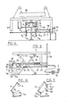
- Figs.1 to 4 diagramatically show the four steps in pallet dispensing using the preferred form of the present invention.
- Fig.1 there is a stack of pallets P1,P2,P3 resting on a floor F.
- a pallet hand truck tyne pair indicated 1 and the numeral 2 indicates the tyne wheels.
- the numeral 3 indicates one of several fingers movable in the direction of the arrow supported by a frame vertically movable in a limited range and able to be locked in at least an elevated position.
- Fig.2 the operating mechanism of the hand truck is indicated 4 and it has been operated after insertion of the tynes 1 into the pallet P3 to raise the pallet stack an amount sufficient to allow the fingers 3 to enter into the pallet P3 and be spaced a small distance below the underface of the top battens of the pallet P2. The support for the fingers 3 is then locked against vertical movement.
- Fig.4 the pallet P3 is removed from the stack on the hand truck.
- the finger support is released and it moves down with the pallet stack in a controlled manner until the lowermost pallet rests on the floor F and the finger support is then raised to locate the fingers at the elevation shown in Fig.1 ready for the process to be repeated next time a pallet is required.
- the illustrated embodiment of the invention provides a "U" shaped frame 5 which supports the fingers 3 in a manner to be described and is vertically movable for a limited distance up and down relative to four vertical angle members 6 interconnected in a suitable manner to provide a holder for a stack of pallets, two of which are shown in Figs.5 and 6. Movement of the frame 5 up and down is through scissor links 5a at opposite sides of the holder linking the holder to the frame 5.
- a first lateral part rotatable shaft 7 provided with attached lever arms 8a and 8b.
- the arm 8a is operatively coupled through a link 9 to a first hydraulic valve 10 for controlling the flow of oil to and from a hydraulic piston in cylinder combination 11.
- the unit 11 is coupled at its ends respectively to the movable frame 5 and the base of the pallet holder formed by the uprights 6. The purpose of the unit 11 will be explained later.
- the arm 8b is connected through a link 3a to one of the rear fingers 3.
- Additional arms 12a, 12b are fixed to the shaft 7.
- the arm 12a is connected through a link 13 including a lost motion linkage to a hydraulic valve 14 which is in circuit with the unit 11 through a flow restrictor 15.
- the arm 12b is connected through another link 3a to the other finger 3 of the rear finger pair.
- a rod 17 which is slidably supported in support members 20 and 21 fixed to the frame 5.
- the rod 17 is biassed in a first direction by a spring 18 around the rod 17 and located between a collar 19 on the rod 17 and the support 20.
- a cam roller 22 at the junction of the rod 17 and the arm 16.
- Another rod 23 is slidably mounted in the support 21.
- the rod 23 is biassed in the opposite direction to the rod 17 by a spring 23 located between a collar 25 on the rod 23 and the support 21.
- Corresponding ends of the rods 17 and 23 are pivotally connected to an operating handle 26.
- a link 27 is pivotally connected to the other end of the rod 23 and the link 27 is fixed to another shaft 28 part rotatably mounted laterally at the rear of the frame 5.
- the shaft 28 has an arm 29 fixed to it (see Fig.11) and when the shaft 28 is part rotated in the operation of the machine the arm 29 will operate the valve 14.
- a cam arrangement fixed to the pallet holder base.
- the cam arrangement comprises a liftable latch arm 30, an abutment member 31 with abutment faces 32 and 34.
- Fig.9 also illustrates a rod 35 connected at one end to the arm 16 and at the other end to a shaft 36 slidably mounted in a bearing 37 on the frame 5.
- One of the front fingers 3 is connected to the shaft 36.
- There is a matching arrangement at the other side of the frame 5 comprising another arm 16 fixed to the shaft 7 and another rod 35 with shaft 36 in a bearing 37 with the other finger 3 of the front finger pair fixed to the shaft 36. It follows that as the shaft 7 rotates the front finger pair will be moved at the same time in the bearings 7 and the rear finger pair will be moved by the arms 8a and 12a and the links 3a.
- the mechanism of control is in the position shown in Fig.9 when the frame 5 is in the elevated operational position. It is to be noted that there is a counterweight, indicated 38 in Fig.8 which is connected to the frame 5 and supported by cables running over pulleys supported from the uprights 6. The purpose of the counterweight will be explained later but when the frame 5 is in the elevated position the counterweight is in a lowered position.
- valve 10 With the frame 5 elevated the valve 10 is open and the valve 14 is closed.
- the operative ends of the fingers 3 (under the influence of the spring 18 tending to turn the shaft 7 anti-clockwise in Fig.9) press hard against the outer edges of the front and rear battens of the second lowest pallet, see Fig.1.
- a pallet truck is then inserted into the lowermost pallet P3 and it is raised by the hand truck and this causes the extension of the unit 11, which is possible because of the open valve 10, until the fingers 3 slide off the edges of the battens and pass under the front and rear battens of the pallet P2 under the influence of the spring 18.
- the hand truck is elevated sufficiently to ensure that all fingers 3 have passed below the pallet battens.
- the pallet P3 With the frame 5 locked in the elevated position the pallet P3 can be removed. There is sufficient clearance between the pallet P3 and floor when the fingers 3 enter the pallet P2 to allow the hand truck to be lowered to rest the pallet P2 on the fingers 3, and then lowered further to separate the pallets P3 and P2 and still have sufficient clearance between the pallet P3 and the ground to allow the pallet P3 to be removed on the hand truck. The weight of the pallet P2 and the other pallets in the pallet stack are now supported on the fingers 3.
- the fingers 3 Due to the engagement of the roller 22 with the faces 32 and 34 the fingers 3 are held spaced from the front and rear alignments of the battens of the pallets in the stack during the elevation of the frame 5. However, as soon as the roller 22 clears the top of the face 32 the spring 18 can expand to press the fingers 3 into contact with the edges of the battens of the pallet P1 with which the fingers 3 are now aligned.
- the pallet dispenser is now ready for a repeat of the foregoing operational sequence and is in the configuration as illustrated in Figs.9,10 and 11.
Landscapes
- De-Stacking Of Articles (AREA)
Applications Claiming Priority (2)
| Application Number | Priority Date | Filing Date | Title |
|---|---|---|---|
| AUPJ014088 | 1988-08-31 | ||
| AU140/88 | 1988-08-31 |
Publications (1)
| Publication Number | Publication Date |
|---|---|
| EP0361696A1 true EP0361696A1 (de) | 1990-04-04 |
Family
ID=3773328
Family Applications (1)
| Application Number | Title | Priority Date | Filing Date |
|---|---|---|---|
| EP89308845A Withdrawn EP0361696A1 (de) | 1988-08-31 | 1989-08-31 | Ausgabegerät für Paletten |
Country Status (3)
| Country | Link |
|---|---|
| US (1) | US4960362A (de) |
| EP (1) | EP0361696A1 (de) |
| NZ (1) | NZ230450A (de) |
Cited By (3)
| Publication number | Priority date | Publication date | Assignee | Title |
|---|---|---|---|---|
| US6357590B1 (en) * | 1997-10-16 | 2002-03-19 | Ladislav Stephan Karpisek | Container base with a floor panel tilting means |
| WO2016009331A1 (en) * | 2014-07-15 | 2016-01-21 | Paul Redman | Multi-stack pallet dispensing apparatus |
| US11230442B2 (en) | 2018-10-24 | 2022-01-25 | Paul Redman | Pallet exchanger and load splitter |
Families Citing this family (7)
| Publication number | Priority date | Publication date | Assignee | Title |
|---|---|---|---|---|
| US5480280A (en) * | 1994-10-21 | 1996-01-02 | Conveying Industries, Inc. | Method and apparatus for dispensing pallets |
| US20040146390A1 (en) * | 2002-10-31 | 2004-07-29 | Lancaster Patrick R. | Pallet dispenser |
| US7201555B1 (en) * | 2003-09-29 | 2007-04-10 | Ronald Earl Smith | Pallet loader and separator |
| US9102480B2 (en) * | 2008-11-10 | 2015-08-11 | Steven A. Snapp | Pallet dispenser |
| US20160176660A1 (en) | 2013-07-16 | 2016-06-23 | Paul Redman | Pallet dispenser and method thereof |
| US10046926B2 (en) * | 2013-07-16 | 2018-08-14 | Paul W. Redman | Pallet dispenser and method thereof |
| US11111089B2 (en) | 2017-06-27 | 2021-09-07 | Paul W. Redman | Pallet blocking apparatus and related method and system |
Citations (3)
| Publication number | Priority date | Publication date | Assignee | Title |
|---|---|---|---|---|
| AT229227B (de) * | 1962-03-29 | 1963-08-26 | Kumag A G Maschinenfabrik | Palettenmagazin |
| DE1280749B (de) * | 1965-03-09 | 1968-10-17 | Holstein & Kappert Maschf | Vorrichtung zur Behandlung eines Stapels von kastenfoermigem Stueckgut |
| DE2839412A1 (de) * | 1978-09-11 | 1980-03-13 | Schenck Ag Carl | Verfahren und vorrichtung zum speichern oder entspeichern von tragrahmen |
Family Cites Families (7)
| Publication number | Priority date | Publication date | Assignee | Title |
|---|---|---|---|---|
| US3043476A (en) * | 1959-05-13 | 1962-07-10 | Crompton & Knowles Packaging C | Feed mechanism for thin flat comestibles |
| US3757971A (en) * | 1971-06-01 | 1973-09-11 | W Frish | Palletizing apparatus |
| DE3047914A1 (de) * | 1980-12-19 | 1982-07-15 | Volkswagenwerk Ag, 3180 Wolfsburg | "stapelvorrichtung fuer teilebehaelter, insbesondere fuer produktionsplaetze" |
| JPS5895036A (ja) * | 1981-11-30 | 1983-06-06 | Yokohama Rubber Co Ltd:The | パレツト供給装置 |
| JPS61132233A (ja) * | 1984-11-30 | 1986-06-19 | Daiwa Kogyo Kk | パレツト供給装置 |
| US4701092A (en) * | 1985-02-15 | 1987-10-20 | Yarbrough'o Machine Shop | Pallet dispenser |
| JPS63247221A (ja) * | 1987-03-31 | 1988-10-13 | Nitto Seiko Co Ltd | 部品収納パレツト移載方法及びその装置 |
-
1989
- 1989-08-28 NZ NZ230450A patent/NZ230450A/xx unknown
- 1989-08-29 US US07/400,161 patent/US4960362A/en not_active Expired - Fee Related
- 1989-08-31 EP EP89308845A patent/EP0361696A1/de not_active Withdrawn
Patent Citations (3)
| Publication number | Priority date | Publication date | Assignee | Title |
|---|---|---|---|---|
| AT229227B (de) * | 1962-03-29 | 1963-08-26 | Kumag A G Maschinenfabrik | Palettenmagazin |
| DE1280749B (de) * | 1965-03-09 | 1968-10-17 | Holstein & Kappert Maschf | Vorrichtung zur Behandlung eines Stapels von kastenfoermigem Stueckgut |
| DE2839412A1 (de) * | 1978-09-11 | 1980-03-13 | Schenck Ag Carl | Verfahren und vorrichtung zum speichern oder entspeichern von tragrahmen |
Cited By (3)
| Publication number | Priority date | Publication date | Assignee | Title |
|---|---|---|---|---|
| US6357590B1 (en) * | 1997-10-16 | 2002-03-19 | Ladislav Stephan Karpisek | Container base with a floor panel tilting means |
| WO2016009331A1 (en) * | 2014-07-15 | 2016-01-21 | Paul Redman | Multi-stack pallet dispensing apparatus |
| US11230442B2 (en) | 2018-10-24 | 2022-01-25 | Paul Redman | Pallet exchanger and load splitter |
Also Published As
| Publication number | Publication date |
|---|---|
| US4960362A (en) | 1990-10-02 |
| NZ230450A (en) | 1991-01-29 |
Similar Documents
| Publication | Publication Date | Title |
|---|---|---|
| US4960362A (en) | Pallet dispenser | |
| EP3022140B1 (de) | Palettenspender und verfahren dafür | |
| DE2447983C3 (de) | Vorrichtung zum Aufstapeln und Zählen von gefalteten Kartonzuschnitten | |
| US10046926B2 (en) | Pallet dispenser and method thereof | |
| CH638738A5 (de) | Schaltvorrichtung fuer die senk- und die schwenkschiene an einer faltschachtelpackmaschine. | |
| DE602005006006T2 (de) | Handhabungseinheit zum palettieren | |
| US4684308A (en) | Stacker assembly for a conveyor system | |
| EP3645436B1 (de) | Vorrichtung zum blockieren von paletten sowie zugehöriges verfahren und system | |
| DE3500056C2 (de) | ||
| US4923357A (en) | Container transfer lift | |
| EP0280828B1 (de) | Lastenhebewerk | |
| CA2215759A1 (en) | Pallet stacking and dispensing unit | |
| DE1927686A1 (de) | Vorrichtung zum Stapeln von Gegenstaenden | |
| EP0320781B1 (de) | Vorrichtung zum Transport und Verlegen von Formsteinen oder Formsteinplatten | |
| JPS61192625A (ja) | パネルを1パツクごと加工機ラインへ送給するための昇降プラツトホ−ムおよびその操作方法 | |
| US3303942A (en) | Concrete block stacking machine | |
| KR200159506Y1 (ko) | 주편 자동분리장치 | |
| DE3230484C2 (de) | ||
| DD258160A1 (de) | Ballenakkumulator | |
| DE133020C (de) | ||
| DE8703517U1 (de) | Vorrichtung zum Transportieren und Verlegen von Formsteinen oder Formsteinpaletten | |
| JPH05132147A (ja) | 角管及び形鋼の段積み装置及び段積み方法 | |
| KR100815750B1 (ko) | 스라브 위치복구장치 | |
| DE862577C (de) | Entladeplattform fuer mit Massenguetern beladene Fahrzeuge | |
| DE3707381C2 (de) |
Legal Events
| Date | Code | Title | Description |
|---|---|---|---|
| PUAI | Public reference made under article 153(3) epc to a published international application that has entered the european phase |
Free format text: ORIGINAL CODE: 0009012 |
|
| AK | Designated contracting states |
Kind code of ref document: A1 Designated state(s): DE FR GB IT |
|
| STAA | Information on the status of an ep patent application or granted ep patent |
Free format text: STATUS: THE APPLICATION IS DEEMED TO BE WITHDRAWN |
|
| 18D | Application deemed to be withdrawn |
Effective date: 19901005 |