EP0361706A1 - Dispositif d'éclairage - Google Patents
Dispositif d'éclairage Download PDFInfo
- Publication number
- EP0361706A1 EP0361706A1 EP89309000A EP89309000A EP0361706A1 EP 0361706 A1 EP0361706 A1 EP 0361706A1 EP 89309000 A EP89309000 A EP 89309000A EP 89309000 A EP89309000 A EP 89309000A EP 0361706 A1 EP0361706 A1 EP 0361706A1
- Authority
- EP
- European Patent Office
- Prior art keywords
- lighting device
- lighting
- krypton lamp
- lamp
- voltage
- Prior art date
- Legal status (The legal status is an assumption and is not a legal conclusion. Google has not performed a legal analysis and makes no representation as to the accuracy of the status listed.)
- Granted
Links
- 229910052743 krypton Inorganic materials 0.000 claims abstract description 78
- DNNSSWSSYDEUBZ-UHFFFAOYSA-N krypton atom Chemical compound [Kr] DNNSSWSSYDEUBZ-UHFFFAOYSA-N 0.000 claims abstract description 78
- 238000010891 electric arc Methods 0.000 claims description 28
- 238000009499 grossing Methods 0.000 claims description 23
- 230000004907 flux Effects 0.000 claims description 7
- 238000009877 rendering Methods 0.000 abstract description 12
- 239000003990 capacitor Substances 0.000 description 28
- XKRFYHLGVUSROY-UHFFFAOYSA-N Argon Chemical compound [Ar] XKRFYHLGVUSROY-UHFFFAOYSA-N 0.000 description 14
- 238000004804 winding Methods 0.000 description 11
- 229910052786 argon Inorganic materials 0.000 description 7
- 208000003464 asthenopia Diseases 0.000 description 6
- 230000000694 effects Effects 0.000 description 6
- 241000251468 Actinopterygii Species 0.000 description 5
- 244000144977 poultry Species 0.000 description 5
- 239000007789 gas Substances 0.000 description 4
- 238000000034 method Methods 0.000 description 4
- 241001465754 Metazoa Species 0.000 description 3
- 235000021167 banquet Nutrition 0.000 description 3
- 230000003796 beauty Effects 0.000 description 3
- 201000010099 disease Diseases 0.000 description 3
- 208000037265 diseases, disorders, signs and symptoms Diseases 0.000 description 3
- 230000002265 prevention Effects 0.000 description 3
- XEEYBQQBJWHFJM-UHFFFAOYSA-N Iron Chemical group [Fe] XEEYBQQBJWHFJM-UHFFFAOYSA-N 0.000 description 2
- 208000007101 Muscle Cramp Diseases 0.000 description 2
- 208000005392 Spasm Diseases 0.000 description 2
- 238000010586 diagram Methods 0.000 description 2
- 230000002070 germicidal effect Effects 0.000 description 2
- 230000012010 growth Effects 0.000 description 2
- 230000020169 heat generation Effects 0.000 description 2
- 238000000554 physical therapy Methods 0.000 description 2
- 230000004436 pseudomyopia Effects 0.000 description 2
- 238000004904 shortening Methods 0.000 description 2
- 230000001960 triggered effect Effects 0.000 description 2
- 208000008035 Back Pain Diseases 0.000 description 1
- 206010065390 Inflammatory pain Diseases 0.000 description 1
- 201000008197 Laryngitis Diseases 0.000 description 1
- 208000000112 Myalgia Diseases 0.000 description 1
- 206010028980 Neoplasm Diseases 0.000 description 1
- 208000008589 Obesity Diseases 0.000 description 1
- 208000005141 Otitis Diseases 0.000 description 1
- 201000007100 Pharyngitis Diseases 0.000 description 1
- 230000005856 abnormality Effects 0.000 description 1
- 206010003246 arthritis Diseases 0.000 description 1
- QVGXLLKOCUKJST-UHFFFAOYSA-N atomic oxygen Chemical compound [O] QVGXLLKOCUKJST-UHFFFAOYSA-N 0.000 description 1
- 230000005540 biological transmission Effects 0.000 description 1
- 239000008280 blood Substances 0.000 description 1
- 210000004369 blood Anatomy 0.000 description 1
- 230000017531 blood circulation Effects 0.000 description 1
- 230000036772 blood pressure Effects 0.000 description 1
- 201000011510 cancer Diseases 0.000 description 1
- 238000010411 cooking Methods 0.000 description 1
- 230000007423 decrease Effects 0.000 description 1
- 230000001934 delay Effects 0.000 description 1
- 208000019258 ear infection Diseases 0.000 description 1
- 230000029142 excretion Effects 0.000 description 1
- 239000011521 glass Substances 0.000 description 1
- 208000006454 hepatitis Diseases 0.000 description 1
- 231100000283 hepatitis Toxicity 0.000 description 1
- 208000014674 injury Diseases 0.000 description 1
- 230000010354 integration Effects 0.000 description 1
- 229910052742 iron Inorganic materials 0.000 description 1
- 238000010030 laminating Methods 0.000 description 1
- 239000000155 melt Substances 0.000 description 1
- 230000002503 metabolic effect Effects 0.000 description 1
- 230000004060 metabolic process Effects 0.000 description 1
- 244000005700 microbiome Species 0.000 description 1
- 208000004296 neuralgia Diseases 0.000 description 1
- 235000020824 obesity Nutrition 0.000 description 1
- 239000013307 optical fiber Substances 0.000 description 1
- 230000010355 oscillation Effects 0.000 description 1
- 239000001301 oxygen Substances 0.000 description 1
- 229910052760 oxygen Inorganic materials 0.000 description 1
- 230000008635 plant growth Effects 0.000 description 1
- 239000000047 product Substances 0.000 description 1
- 230000002035 prolonged effect Effects 0.000 description 1
- 206010044008 tonsillitis Diseases 0.000 description 1
- 230000008733 trauma Effects 0.000 description 1
- 238000009834 vaporization Methods 0.000 description 1
- 230000008016 vaporization Effects 0.000 description 1
- 208000037911 visceral disease Diseases 0.000 description 1
- 230000000007 visual effect Effects 0.000 description 1
- 208000011293 voice disease Diseases 0.000 description 1
Images


Classifications
-
- H—ELECTRICITY
- H05—ELECTRIC TECHNIQUES NOT OTHERWISE PROVIDED FOR
- H05B—ELECTRIC HEATING; ELECTRIC LIGHT SOURCES NOT OTHERWISE PROVIDED FOR; CIRCUIT ARRANGEMENTS FOR ELECTRIC LIGHT SOURCES, IN GENERAL
- H05B39/00—Circuit arrangements or apparatus for operating incandescent light sources
- H05B39/04—Controlling
- H05B39/041—Controlling the light-intensity of the source
-
- Y—GENERAL TAGGING OF NEW TECHNOLOGICAL DEVELOPMENTS; GENERAL TAGGING OF CROSS-SECTIONAL TECHNOLOGIES SPANNING OVER SEVERAL SECTIONS OF THE IPC; TECHNICAL SUBJECTS COVERED BY FORMER USPC CROSS-REFERENCE ART COLLECTIONS [XRACs] AND DIGESTS
- Y02—TECHNOLOGIES OR APPLICATIONS FOR MITIGATION OR ADAPTATION AGAINST CLIMATE CHANGE
- Y02B—CLIMATE CHANGE MITIGATION TECHNOLOGIES RELATED TO BUILDINGS, e.g. HOUSING, HOUSE APPLIANCES OR RELATED END-USER APPLICATIONS
- Y02B20/00—Energy efficient lighting technologies, e.g. halogen lamps or gas discharge lamps
Definitions
- the present invention relates to a lighting device using krypton lamp as the light source, in particular, to a lighting device wherein krypton lamp is lighted by energizing a voltage exceeding its rating.
- Fluorescent lamp has the merit that its relatively high total flux provides a bright lighting, as well as having the demerits that its flicker tends to cause eyestrain, and that the unbalance between total flux and color temperature deteriorates the color rendering properties to make articles look paler than they really are.
- incandescent lamp is superior to fluorescent lamp because the well balance between total flux and color temperature achieves satisfiable color rendering properties, incandescent lamp has the demerit that it is generally low in total flux and this tends to cause eyestrain when used in lighting for long time.
- the present inventor investigated incandescent lamps having superior color rendering properties. As the result, the present inventor found that a light obtained by applying to an incandescent lamp a voltage exceedings its rating attains a color temperature approximately the same as that of early morning sunlight (about 3,000K) which is comfort severelyable to the eyes, as well as that such a light is suitable for general lighting.
- the present inventor disclosed these in Japanese Patent Laid-Opens No.193,398/86, No.185,516/87, No.26,909/88 and No.88,792/88.
- argon lamp wherein argon gas is enclosed as the filling gas. Although argon lamp achieves a service life of about 1,000 hours when lighted by energizing the rated voltage, energization of an overvoltage extremely shortens the service life even when the overvoltage is dc.
- the present inventor investigated various light sources which emit long time a natural light having a color temperature of about 2,900K or higher, desirably, in the range of about 2,950 to about 3,050K, as well as having superior color rendering properties.
- krypton lamp emits a natural light having both color temperature of about 2,900K or higher, desirably, in the range of about 2,950 to about 3,050K and superior color rendering properties when lighted by energizing a voltage exceeding the rating, desirably, exceeding 110% but not exceeding 150% thereof, as well as that such a light is suitable for general lighting.
- the present invention relates to a lighting device using krypton lamp as the light source, characterized by providing a power source capable of supplying to a krypton lamp a voltage exceeding its rating; and lighting said krypton lamp by energizing said voltage.
- krypton lamp is slightly higher in total flux and longer in service life than argon lamp, i.e. 2,000 hours to 1,000 hours. Both lamps are, however, relatively low in color temperature, i.e. up to 2,850K, which is insufficiently low for use in lighting.
- the present invention uses krypton lamp as the light source, which is allowed to emit long time a natural light having both color temperature of about 2,900K or higher, desirably, in the range of about 2,950 to about 3,050K and superior color rendering properties.
- krypton lamp as referred to in the invention means incandescent tungstein filament lamp wherein the filling gas comprises or consists of krypton gas.
- Any krypton lamp can be used in the invention regardless of their rated voltage, rated wattage, efficiency and shape, provided that it emits a continuous light having a color temperature of about 2,900K or higher, desirably, in the range of about 2,950 to about 3,050K when energized a voltage exceeding 110% of the rating but not exceeding 150% thereof.
- Such a krypton lamp is a commercialized krypton lamp with a rated wattage of 25 to 150W, or that which is specially designed and prepared to give a desired rated voltage, rated wattage, efficiency and shape.
- the power source to supply to krypton lamp a voltage exceeding its rating is that which can supply to a krypton lamp an ac or a dc voltage exceeding its rating, desirably, exceeding 110% but not exceeding 150% thereof when connected with one or more krypton lamps to output terminal(s).
- Such power source can be stabilized with an electric circuitry.
- an ac voltage exceeding its rating for example, an ac or a dc voltage from commercial ac line, generator or battery is controlled with a suitable means such as transformer and power converter into a voltage exceeding the rating, desirably, exceeding 110% but not exceeding 150% thereof, and then applied to the krypton lamp:
- a lamp lighting device disclosed in Japanese Patent Laid-Open No. 136,492/88 by the present inventor is suitable for such power source.
- a dc voltage exceeding its rating besides using battery, an ac voltage, for example, from commercial ac line or generator is rectified and smoothed with a rectifier circuit bearing a smoothing means, and the obtained dc voltage exceeding the rating but not exceeding 150% thereof is supplied to the krypton lamp:
- lamp lighting devices disclosed in Japanese Patent Laid-Opens No. 193,398/86, No. 185,516/87 and No.26,909/88 by the present inventor are extremely suitable for such power source.
- an ac voltage for example, from commercial ac line or generator is rectified and smoothed with a rectifier circuit bearing a smoothing means, and the obtained dc voltage is fed to an inverter circuit into a high-frequency voltage which is then applied intact to a krypton lamp, or converted with a rectifier circuit into a dc voltage exceeding the rating, desirably, exceeding 110% but not exceeding 150% thereof prior to application to the krypton lamp.
- the method wherein an ac voltage is converted with a rectifier circuit bearing a smoothing means into a dc voltage which is then applied to krypton lamp is superior to the other two methods because of the facts that the power source for this method can be so simplified that a voltage exceeding the rating but not exceeding 150% thereof can be easily obtained only by controlling the capacitance of the smoothing means; and that the obtained light is flickerless and much more natural and closer to the sunlight than that obtained by lighting krypton lamp with an ac voltage exceeding the rating.
- the light obtained in this way usually, has a color temperature of about 2,900K or higher, desirably, in the range of about 2,950 to about 3,050K, and the service life at this time is usually about 200 hours or longer which causes no problem when practically used.
- krypton lamp is lighted by energizing a dc voltage obtained by rectifying and smoothing an ac voltage with a rectifier circuit which bears a smoothing means
- argon lamp is applied with argon lamp.
- krypton lamp achieves a service life of about 200 hours or longer which reaches up to about 4-folds of that attained by supplying to argon lamp a voltage exceeding its rating to emit a light having a color temperature of about 2,900K or higher.
- Such a service life is about 2-folds or much longer than that expected from the inherent lives of krypton and argon lamps (2,000 and 1,000 hours respectively).
- the life of one krypton lamp is much more prolonged than in the case of lighting one krypton lamp in continuous manner.
- the lighting device is advantageously usable as table and desk lightings, for example, adjustable lamp, desk lamp, hurricane lamp, table lamp and mini lamp; indoor and outdoor lightings, for example, ceiling fixture, wall fixture, pendant, chandelier, swag lamp and floor lamp, garden lamp and porch for the lighting of study room, children's room, bed room, living room, dining room, kitchen, toilet room, washroom, bath room, passage, stairs, balcony and porch in detached house, apartment house and multiple house, as well as for lighting of reading room, schoolroom, hall, lobby, waiting room, treating room, control room, office room, drawing room, laboratory, lounge, guest room, clerk room, cooking room, operating room and cultivating room in facilities such as library, school, studio, beauty salon, hospital, factory, office, "ryokan (Japanese-style hotel)", hotel, restaurant, banquet hall, wedding hall, conference hall, store, shop, supermarket, department store, art museum, museum, concert hall, hall, airplane, vehicle, pool, gymnasium, sports ground, poultry farm, fish farm
- One or more lighting units prepared according to the invention can be subjected to a lighting pattern control, time schedule control, daylight interlocking control, wall switch control, centralized control and/or dimming control by appropriately locating the lighting unit(s) in the above described house and facilities, and subjecting the lighting unit(s) to a lighting control system using dimming and switching circuits, for example, wire control systems such as individual wiring system, personal wiring multiplex system, telephone line system, power line carrier system and optical fiber system and wireless control systems such as electric wave control system, light control system, ultrasonic control system and acoustic control system.
- one or more lighting devices of the present invention can be totally controlled together with other electric equipments by incorporating the lighting device(s) into a home bus system.
- the lighting device provides a natural light which is close to early morning sublight and exhibits remarkable effects in the prevention and treatment of diseases, for example, pseudomyopia, asthenopia and depression and also in the improvement of growth and productivity of animals and plants
- the lighting device can be advantageously used to practice physical therapy at home and infirmaries such as hospital and clinic, as well as a lighting device for farms and factories such as poultry farm, fish farm and plant factory.
- the light obtained by lighting krypton lamp by energizing a voltage exceeding its rating is rich in infrared component, in particular, a far-red component with a wavelength of 25 to 1,000 microns.
- the far-red component has an activity of accelerating the perspiration, oxygen intake and blood circulation in animals to promote or improve their metabolism, lowering of blood pressure and blood sugar, excretion of metabolic products, relieving of obesity and rehabilitation, as well as having an activity of relieving inflammatory pains and spasms.
- the lighting device of the invention exhibits remarkable effects in the relaxation of myonic tonus by stiff shoulder and myalgia; in the relieving of spasms and dorsal pains by trauma, burn, rheumatism, arthritis, lambago, neuralgia, extermal otitis, tymanitis, nasosinusitis, tonsillitis, pharyngitis, laryngitis, throaty voice, and visceral diseases; and in the prevention and treatment of geriatric diseases such as cancer, hepatitis and hepatocirrhosis when equipped with a krypton lamp using a lead-free or low lead content glass bulb for higher infrared transmission.
- Such lighting device can be advantageously used to practice physical therapy at home and infirmaries such as hospital and clinic.
- the present lighting device can be advantageously used as a germicidal lamp, as well as a lighting for cultivating rooms such as plant factory.
- reference numeral (1) designates arc discharge current-limiting circuit; (2), rush current-limiting circuit; (3), lighting control device; (4), inverter circuit; D, rectifier diode; KL, krypton lamp; AC, ac power source; SW, switch; R, resistor; C, capacitor; T, transformer; Tr, transistor; L, inductor or winding; Q, thyristor; Z, zener diode; Th, thermistor; U, lighting unit; and F, fuse.
- a rectifier circuit comprising a bridge rectifier D and a smoothing capacitor C is connected to an ac terminal of an ac source AC through an arc discharge current-limiting circuit (1), while a krypton lamp KL is connected with a dc terminal of the bridge circuit D through a rush current-limiting circuit (2).
- the arc discharge current-limiting circuit (1) is to limit an arc discharge current which may occur upon burnout of lamp filament, as well as to stop the arc discharge per se.
- Such an arc discharge usually occurs in short-circuit manner to arise in the main current circuit a continuous current surge of up to 200 amperes which has a possibility of greatly damaging circuits elements such as rectifier and thyristor.
- inductance, capacitance and resistance of the inductor, capacitor and resistor used in the arc discharge current-limiting circuit (1) are set in such manner that, when the main current circuit is in stationary state, they cause no substantial voltage drop at the ac terminal of the rectifier D, but effectively limits an arc discharge current to suspend the arc discharge if such an arc discharge occurs.
- inductor is the most desirable element which is used to compose the arc discharge current-limiting circuit (1).
- An inductor of coreless- or core-type such as winding iron core-type and laminating iron-type can be used as the inductor, as long as it limits arc discharge current when connected with the ac terminal of the rectifier circuit bearing a smoothing capacitor C.
- the inductance of such inductor is chosen in such manner that the resonance circuit formed together with the smoothing capacitor C advances the phase difference between the voltage and current components in arc discharge current, in other words, decreases its effective power.
- the use of an inductor with a relatively low dc resistance results in a less heat generation by the inductor per se, as well as in an effective limitation of arc discharge current.
- a desirable inductance lies in the range of about 1 to about 10 millihenries when the capacitance of the smoothing capacitor C is about 30 to about 100 microfarads.
- the arc discharge current-limiting circuit (1) also limits switch-on rush currents into krypton lamp and smoothing current which will be described hereinafter.
- the filament resistance of krypton lamp at ambient temperature is several tenth parts of that in incandescent state. With this reason, the application of a voltage exceeding the rating of krypton lamp results in a rush current which may reach up to several folds of stationary current or higher to accelerate the vaporization and burnout of the lamp filament.
- the rush current-limiting circuit (2) is to limit such a rush current and also to prevent the shortening of life due to the rush current.
- the rush current-limiting circuit (2) usually comprises a current limiting means such as resistor which is connected in series with krypton lamp, a thyristor having a main current path connected in parallel with the current limiting means, and a triggering circuit which delays the conduction of the thyristor by a prescribed time after switch-on.
- the resistance of the current limiting means is chosen in such manner that its combined resistance with the filament at ambient temperature is approximately the same as the filament resistance in incandescent state. With this arrangement, the current limiting means is left connected in series with krypton lamp over the prescribed time to limit possible rush current and also to preheat the filament. After a lapse of the prescribed time, the thyristor is triggered to bypass the current limiting means to supply to krypton lamp a voltage exceeding its rating. Thus, the rush current into krypton lamp can be extremely reduced or even eliminated.
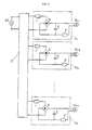
- FIG.2 is an example of a lighting system wherein a plurality of lighting units as shown in FIG.1 are controlled by a lighting control device using, for example, dimming and switching circuits.
- a plurality of lighting units U1, U2 ... U n respectively comprising a rectifier circuit bearing a smoothing circuit as shown in FIG. 1, an arc discharge current-limiting circuit, and a rush current-limiting circuit are equipped with krypton lamps KL1, KL2 ... KL n having a desired rated wattage, and connected with an ac source AC through a lighting control device (3) which bears, for example, dimming and switching circuits.
- the lighting control device (3) and the power sources and krypton lamps in respective lighting units can be located as follows:
- the lighting control device (3) and power sources are located at the same place, while the krypton lamps are located at desired places in houses and facilities such as library, school, studio, beauty salon, hospital, factory, office, "ryokan", hotel, restaurant, banquet hall, wedding hall, conference hall, store, shop, supermarket, department store, art museum, museum, concert hall, hall, airplane, vehicle, pool, gymnasium, poultry farm, fish farm and plant factory.
- the lighting control device (3) is located at an appropriate place in houses and facilities, while a plurality of units containing a power source and a krypton lamp are located at desired places in the houses and facilities.
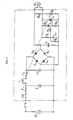
- FIG.3 shows an electric circuit of the lighting device or unit as shown in FIG.1 or 2.
- an ac terminal of a bridge rectifier consisting of rectifier diodes D1, D2, D3 and D4 is connected with a power source AC through a power switch SW, fuses F1 and F2 and inductor L, while a dc terminal of the bridge rectifier is connected with a smoothing capacitor C1 and a krypton lamp KL through a triggering circuit consisting of resistors R1, R2, R3, R4 and R5, a capacitor C2 and thyristors Q1 and Q2, and through a resistor R6 as rush current-limiting circuit.
- a capacitor C3 and a zener diode Z both connected with the ac terminal of the bridge rectifier are to absorb pulse voltages which may occur at the ac terminal to stabilize its input voltage.
- the resistor R6 and fuse F2 are arranged to operate in association so that, if the temperature of the resistor R6 increases with an abnormality, the fuse F2 melts off to automatically break the main current circuit.
- While charging of the capacitor C2 in the triggering circuit is initiated immediately after switch-on of the power switch SW, and, after a lapse of the time as determined by the time constant of the resistor R4 and capacitor C2, the voltage across the capacitor C2 is applied to a gate of the thyristor Q1 to bring it into conduction.
- the conduction current through the thyristor Q1 is applied in turn to a gate of the thyristor Q2 to bring it conduction.
- Conduction of the thyristor Q2 bypasses the resistor R6 connected in parallel with a main current path of the thyristor Q2.
- a prescribed voltage is applied to the krypton lamp KL.
- the filament resistance of the krypton lamp KL immediately after switch-on of the power switch SW is several tenth parts of that in incandescent state, shortening of the life due to rush current can be prevented by setting the resistor R6 in such manner that its combined resistance with the filament is approximately equal to its resistance in incandescent state.
- the rush current into the krypton lamp KL can be substantially eliminated.
- this example has the merits that the thyristor Q2 can be triggered with a relatively small current because in this example two thyristors are used in cascade connection, and that, even when the ambient temperature greatly varies, the triggering circuit is much more surely operated than in the case of using only one thyristor.
- the inductor L provided at the ac terminal of the bridge rectifier effectively makes a loss on any current surge into the main current circuit to suspend such an arc discharge current and also to stop the arc discharge per se. If the arc discharge restores, it is suppressed again by the inductor L and never continues even after the filament gap is enlarged. Furthermore, if the power switch SW is still closed after the arc discharge is stopped, the arc discharge never restore because the filament has been burn out.
- a flickerless natural light having a color temperature of about 2,900K or higher desirably, in the range of about 2,950 to about 3,050K and superior color rendering properties can be obtained with a krypton lamp by energizing a dc voltage exceeding its rating, desirably, exceeding 110% but not exceeding 150% thereof.
- this example can be safely used because, if burnout of filament arises an arc discharge, it effectively limits the current surge due to the arc discharge.
- FIG.4 is an electric circuit of another embodiment according to the invention using an inverter circuit.
- An ac terminal of a bridge rectifier D1 is connected with an ac source AC, while a dc terminal of the bridge rectifier D1 is connected with a smoothing capacitor C1.
- An input terminal of an inverter circuit (4) generating a high-frequency current is connected between both ends of the capacitor C1, while an output terminal of the inverter circuit (4) is connected through a rectifier diode D2 with an integration circuit comprising a capacitor C2.
- a krypton lamp KL is connected between both ends of the capacitor C2.
- an inverter transformer T and a transistor Tr and a capacitor C3 is connected in parallel with a primary winding L1 of the inverter transformer T.
- Both ends of the capacitor C3 are connected with a positive end of the smoothing capacitor C1 and a collector of the transistor Tr.
- One end of a base winding L2 of the inverter transformer T is connected with a base of the transistor Tr through a capacitor C4, while the other end of the base winding L2 is connected with a negative end of the smoothing capacitor C1.
- the base of the transistor Tr is also connected with a positive end of the smoothing capacitor C1 through a resistor R.
- a second winding L3 of the inverter transformer T provides an output terminal of the inverter circuit (4), and particular circuit constants of the inverter circuit (4) and capacitor C2 are chosen in such manner that the voltage across the krypton lamp KL exceeds the effective voltage of the ac source AC, desirably, exceeding 110% but not exceeding 150% thereof, as well as that the current across the filament is, desirably, in the range of 110% of the rating but not exceeding 150% thereof.
- the ac current therefrom is subjected to full-wave rectification by the bridge rectifier D1, and smoothed by the smoothing capacitor C1 into a pulsating or a dc current which is then supplied to the inverter circuit (4).
- This induces the oscillation of the inverter circuit (4) to output a high-frequency voltage at the secondary winding L3 of the inverter transformer T.
- the high-frequency voltage is subjected to half-wave rectification by the diode D2, integrated by the capacitor C2, and supplied to the krypton lamp KL.
- this example is arranged in this way, a natural light having a color temperature of about 2,900K or higher, desirably, in the range of about 2,950 to about 3,050K and superior color rendering properties can be obtained with a krypton lamp over a long period of time by lighting it with a voltage exceeding its rating, desirably, exceeding 110% but not exceeding 150% thereof.
- FIG.5 is an electric circuit of still another embodiment according to the invention, wherein krypton lamp is lighted by energizing an ac voltage exceeding the rating.
- secondary windings L2, L3, L4 and L5 having respective winding ratio, for example, of 100:12, 100:13, 100:14 and 100:15 against a primary winding L1, and a power switch SW1 is provided in such manner that it can be operated in association with a switch SW2 which is used to switch the secondary windings.
- a thermistor Th is provided in the secondary circuit of the transformer T so that rush current due to switch-on of the power switch SW1 is limited by utilizing the property of thermistor that its electric resistance lowers as the ambient temperature increases.
- this example is arranged in this way, a natural light having a slight flicker but having a color temperature of about 2,900K or higher, desirably, in the range of about 2,950 to about 3,050K can be obtained with a krypton lamp over a long period of time by lighting it with an ac voltage exceeding its rating, desirably, exceeding 110% but not exceeding 150% thereof.
- this example can be simplified because the transformer T also limits rush current due to switch-on of the power switch SW1, and the attachment of the transformer T to the bottom of the lighting device helps it to stabilizes its settlement.
- krypton lamp is attached to the lighting device, of course, a plurality of krypton lamps can be simultaneously lighted with one lighting device when the total wattage of the krypton lamps are within the power capacity of the transformer T.
- krypton lamp is lighted by energizing a voltage exceeding its rating, a natural light having a color temperature of about 2,900K or higher and superior color rendering properties which are appropriate to general lighting can be obtained with krypton lamp for long time.
- the present lighting device attains a flickerless and less eyestrain-causative light when lighted by energizing a dc voltage exceeding the rating.
- one krypton lamp can be used for longer time by providing an arc discharge current-limiting circuit and a rush current-limiting circuit respectively at an ac terminal and a dc terminal of the rectifier circuit.
- the present lighting device can be advantageously used for lighting of various houses and facilities such as library, school, studio, beauty salon, hospital, factory, office, "rhyokan", hotel, restaurant, banquet hall, wedding hall, conference hall, store, shop, supermarket, department store, art museum, museum, concert hall, hall, airplane, vehicle, pool, gymnasium, poultry farm, fish farm and plant factory.
- the present lighting device provides a natural light close to morning sunlight which exhibits remarkable effects in the prevention and treatment of diseases, for example, pseudomyoxia, asthenopia and depression, as well as in the improvement of growth and productivity of animals and plants, the present lighting device can be advantageously used as luminare for farms and factories such as poultry farm, fish farm and plant factory.
- the present invention attaining such remarkable effects would greatly contribute to the art.
Landscapes
- Circuit Arrangement For Electric Light Sources In General (AREA)
- Liquid Crystal Substances (AREA)
- Vehicle Body Suspensions (AREA)
- Polarising Elements (AREA)
- Seal Device For Vehicle (AREA)
- Non-Portable Lighting Devices Or Systems Thereof (AREA)
- Liquid Crystal (AREA)
- Control Of Eletrric Generators (AREA)
- Luminescent Compositions (AREA)
- Pressure Welding/Diffusion-Bonding (AREA)
Applications Claiming Priority (2)
| Application Number | Priority Date | Filing Date | Title |
|---|---|---|---|
| JP63223538A JP2779938B2 (ja) | 1988-09-08 | 1988-09-08 | 照明装置 |
| JP223538/88 | 1988-09-08 |
Publications (2)
| Publication Number | Publication Date |
|---|---|
| EP0361706A1 true EP0361706A1 (fr) | 1990-04-04 |
| EP0361706B1 EP0361706B1 (fr) | 1994-12-14 |
Family
ID=16799728
Family Applications (1)
| Application Number | Title | Priority Date | Filing Date |
|---|---|---|---|
| EP89309000A Expired - Lifetime EP0361706B1 (fr) | 1988-09-08 | 1989-09-06 | Dispositif d'éclairage |
Country Status (12)
| Country | Link |
|---|---|
| EP (1) | EP0361706B1 (fr) |
| JP (1) | JP2779938B2 (fr) |
| KR (1) | KR900005848A (fr) |
| AT (1) | ATE115826T1 (fr) |
| BR (1) | BR8904526A (fr) |
| DE (1) | DE68919971T2 (fr) |
| DK (1) | DK442889A (fr) |
| ES (1) | ES2068250T3 (fr) |
| FI (1) | FI97936C (fr) |
| GR (1) | GR3015371T3 (fr) |
| IL (1) | IL91516A (fr) |
| NO (1) | NO893598L (fr) |
Cited By (8)
| Publication number | Priority date | Publication date | Assignee | Title |
|---|---|---|---|---|
| EP0410761A3 (fr) * | 1989-07-27 | 1991-03-20 | Hayashibara, Ken | Dispositif d'éclairage |
| EP0470750A3 (en) * | 1990-08-09 | 1992-12-02 | Hayashibara, Ken | Switching power supply for an incandescent lamp |
| EP0508594A3 (en) * | 1991-03-08 | 1992-12-23 | Hayashibara, Ken | Lighting device |
| EP0508593A3 (en) * | 1991-04-09 | 1992-12-23 | Hayashibara, Ken | Filling composition for incandescent lamp, and incandescent lamp containing the same and its use |
| EP0545514A1 (fr) * | 1991-12-06 | 1993-06-09 | Hayashibara, Ken | Dispositif d'éclairage |
| EP0545513A1 (fr) * | 1991-12-06 | 1993-06-09 | Hayashibara, Ken | Dispositif d'éclairage |
| CN103762835A (zh) * | 2014-01-24 | 2014-04-30 | 成都熊谷加世电器有限公司 | 一种开机浪涌电流抑制电路 |
| CN112542036A (zh) * | 2020-12-08 | 2021-03-23 | 大力电工襄阳股份有限公司 | 高压可控硅无线触发设备 |
Families Citing this family (2)
| Publication number | Priority date | Publication date | Assignee | Title |
|---|---|---|---|---|
| US5343122A (en) * | 1989-07-27 | 1994-08-30 | Ken Hayashibara | Luminaire using incandescent lamp as luminous source |
| ES2163996B1 (es) * | 1999-10-13 | 2003-02-16 | Sanchez Jose Gregori Hernandez | Iluminacion a continua por convertidores ac/dc |
Citations (6)
| Publication number | Priority date | Publication date | Assignee | Title |
|---|---|---|---|---|
| EP0121917A1 (fr) * | 1983-04-08 | 1984-10-17 | TRILUX-LENZE GmbH & Co. KG | Dispositif électronique pour faire fonctionner des lampes à fluorescence |
| DE3001755C2 (de) * | 1980-01-17 | 1985-08-22 | Dieter 1000 Berlin Binninger | Verfahren zur Verlängerung der Lebensdauer von Allgebrauchsglühlampen |
| JPS61193398A (ja) * | 1985-02-20 | 1986-08-27 | 林原 健 | 白熱電球点燈装置 |
| JPS62185516A (ja) * | 1986-02-10 | 1987-08-13 | 林原 健 | 突入電流制限装置 |
| JPS63136492A (ja) * | 1986-11-27 | 1988-06-08 | 林原 健 | ランプ点燈装置 |
| JPH06326909A (ja) * | 1993-05-11 | 1994-11-25 | Funai Electric Co Ltd | 撮影機の画郭表示機構 |
Family Cites Families (3)
| Publication number | Priority date | Publication date | Assignee | Title |
|---|---|---|---|---|
| JPS57197744A (en) * | 1981-05-30 | 1982-12-04 | Tokyo Shibaura Electric Co | Incandescent bulb |
| JPS60172162A (ja) * | 1984-02-15 | 1985-09-05 | 松下電子工業株式会社 | 管状電球 |
| JPS61165997A (ja) * | 1984-12-10 | 1986-07-26 | 林原 健 | 白熱電球点燈装置 |
-
1988
- 1988-09-08 JP JP63223538A patent/JP2779938B2/ja not_active Expired - Lifetime
-
1989
- 1989-09-04 IL IL91516A patent/IL91516A/xx not_active IP Right Cessation
- 1989-09-06 EP EP89309000A patent/EP0361706B1/fr not_active Expired - Lifetime
- 1989-09-06 AT AT89309000T patent/ATE115826T1/de not_active IP Right Cessation
- 1989-09-06 FI FI894218A patent/FI97936C/fi not_active IP Right Cessation
- 1989-09-06 ES ES89309000T patent/ES2068250T3/es not_active Expired - Lifetime
- 1989-09-06 DE DE68919971T patent/DE68919971T2/de not_active Expired - Fee Related
- 1989-09-07 NO NO89893598A patent/NO893598L/no unknown
- 1989-09-07 DK DK442889A patent/DK442889A/da not_active Application Discontinuation
- 1989-09-08 BR BR898904526A patent/BR8904526A/pt unknown
- 1989-09-08 KR KR1019890013034A patent/KR900005848A/ko not_active Abandoned
-
1995
- 1995-03-13 GR GR940403877T patent/GR3015371T3/el unknown
Patent Citations (6)
| Publication number | Priority date | Publication date | Assignee | Title |
|---|---|---|---|---|
| DE3001755C2 (de) * | 1980-01-17 | 1985-08-22 | Dieter 1000 Berlin Binninger | Verfahren zur Verlängerung der Lebensdauer von Allgebrauchsglühlampen |
| EP0121917A1 (fr) * | 1983-04-08 | 1984-10-17 | TRILUX-LENZE GmbH & Co. KG | Dispositif électronique pour faire fonctionner des lampes à fluorescence |
| JPS61193398A (ja) * | 1985-02-20 | 1986-08-27 | 林原 健 | 白熱電球点燈装置 |
| JPS62185516A (ja) * | 1986-02-10 | 1987-08-13 | 林原 健 | 突入電流制限装置 |
| JPS63136492A (ja) * | 1986-11-27 | 1988-06-08 | 林原 健 | ランプ点燈装置 |
| JPH06326909A (ja) * | 1993-05-11 | 1994-11-25 | Funai Electric Co Ltd | 撮影機の画郭表示機構 |
Cited By (9)
| Publication number | Priority date | Publication date | Assignee | Title |
|---|---|---|---|---|
| EP0410761A3 (fr) * | 1989-07-27 | 1991-03-20 | Hayashibara, Ken | Dispositif d'éclairage |
| EP0470750A3 (en) * | 1990-08-09 | 1992-12-02 | Hayashibara, Ken | Switching power supply for an incandescent lamp |
| EP0508594A3 (en) * | 1991-03-08 | 1992-12-23 | Hayashibara, Ken | Lighting device |
| EP0508593A3 (en) * | 1991-04-09 | 1992-12-23 | Hayashibara, Ken | Filling composition for incandescent lamp, and incandescent lamp containing the same and its use |
| EP0545514A1 (fr) * | 1991-12-06 | 1993-06-09 | Hayashibara, Ken | Dispositif d'éclairage |
| EP0545513A1 (fr) * | 1991-12-06 | 1993-06-09 | Hayashibara, Ken | Dispositif d'éclairage |
| CN103762835A (zh) * | 2014-01-24 | 2014-04-30 | 成都熊谷加世电器有限公司 | 一种开机浪涌电流抑制电路 |
| CN103762835B (zh) * | 2014-01-24 | 2016-01-20 | 成都熊谷加世电器有限公司 | 一种开机浪涌电流抑制电路 |
| CN112542036A (zh) * | 2020-12-08 | 2021-03-23 | 大力电工襄阳股份有限公司 | 高压可控硅无线触发设备 |
Also Published As
| Publication number | Publication date |
|---|---|
| FI894218L (fi) | 1990-03-09 |
| FI97936B (fi) | 1996-11-29 |
| DK442889A (da) | 1990-03-09 |
| KR900005848A (ko) | 1990-04-14 |
| EP0361706B1 (fr) | 1994-12-14 |
| IL91516A (en) | 1993-05-13 |
| NO893598D0 (no) | 1989-09-07 |
| JP2779938B2 (ja) | 1998-07-23 |
| IL91516A0 (en) | 1990-04-29 |
| NO893598L (no) | 1990-03-09 |
| BR8904526A (pt) | 1990-04-24 |
| GR3015371T3 (en) | 1995-06-30 |
| FI97936C (fi) | 1997-03-10 |
| FI894218A0 (fi) | 1989-09-06 |
| ES2068250T3 (es) | 1995-04-16 |
| ATE115826T1 (de) | 1994-12-15 |
| DE68919971D1 (de) | 1995-01-26 |
| DE68919971T2 (de) | 1995-05-24 |
| DK442889D0 (da) | 1989-09-07 |
| JPH0272599A (ja) | 1990-03-12 |
Similar Documents
| Publication | Publication Date | Title |
|---|---|---|
| US5343122A (en) | Luminaire using incandescent lamp as luminous source | |
| KR100257588B1 (ko) | 백열 전구용 봉입 조성물과 이것을 봉입한 백열 전구 및 그 용도 | |
| US4251752A (en) | Solid state electronic ballast system for fluorescent lamps | |
| US5424618A (en) | Arrangements for reducing interference from a dimming system, and dimmer therefor | |
| US6433493B1 (en) | Electronic power converter for triac based controller circuits | |
| US5126636A (en) | Lighting device | |
| EP0361706B1 (fr) | Dispositif d'éclairage | |
| US5537008A (en) | High voltage incandescent lamp with low-pressure Kr/N2 gas fill | |
| KR100240048B1 (ko) | 조명장치 | |
| EP0470750B1 (fr) | Alimentation à découpage pour lampe à incandescence | |
| EP0545514B1 (fr) | Dispositif d'éclairage | |
| US4523129A (en) | Modular lighting control with circulating inductor | |
| JP3472315B2 (ja) | 白熱電球用封入組成物とその用途 | |
| JP3419793B2 (ja) | 照明装置 | |
| EA040866B1 (ru) | Управляющая цепь освещения, осветительная установка и способ |
Legal Events
| Date | Code | Title | Description |
|---|---|---|---|
| PUAI | Public reference made under article 153(3) epc to a published international application that has entered the european phase |
Free format text: ORIGINAL CODE: 0009012 |
|
| AK | Designated contracting states |
Kind code of ref document: A1 Designated state(s): AT BE CH DE ES FR GB GR IT LI LU NL SE |
|
| 17P | Request for examination filed |
Effective date: 19900731 |
|
| 17Q | First examination report despatched |
Effective date: 19930311 |
|
| GRAA | (expected) grant |
Free format text: ORIGINAL CODE: 0009210 |
|
| AK | Designated contracting states |
Kind code of ref document: B1 Designated state(s): AT BE CH DE ES FR GB GR IT LI LU NL SE |
|
| PG25 | Lapsed in a contracting state [announced via postgrant information from national office to epo] |
Ref country code: GR Free format text: LAPSE BECAUSE OF FAILURE TO SUBMIT A TRANSLATION OF THE DESCRIPTION OR TO PAY THE FEE WITHIN THE PRESCRIBED TIME-LIMIT Effective date: 19941214 |
|
| REF | Corresponds to: |
Ref document number: 115826 Country of ref document: AT Date of ref document: 19941215 Kind code of ref document: T |
|
| ITF | It: translation for a ep patent filed | ||
| REF | Corresponds to: |
Ref document number: 68919971 Country of ref document: DE Date of ref document: 19950126 |
|
| EAL | Se: european patent in force in sweden |
Ref document number: 89309000.1 |
|
| ET | Fr: translation filed | ||
| REG | Reference to a national code |
Ref country code: ES Ref legal event code: FG2A Ref document number: 2068250 Country of ref document: ES Kind code of ref document: T3 |
|
| REG | Reference to a national code |
Ref country code: GR Ref legal event code: FG4A Free format text: 3015371 |
|
| PG25 | Lapsed in a contracting state [announced via postgrant information from national office to epo] |
Ref country code: AT Effective date: 19950906 |
|
| PG25 | Lapsed in a contracting state [announced via postgrant information from national office to epo] |
Ref country code: LU Free format text: LAPSE BECAUSE OF NON-PAYMENT OF DUE FEES Effective date: 19950930 Ref country code: BE Effective date: 19950930 |
|
| PLBE | No opposition filed within time limit |
Free format text: ORIGINAL CODE: 0009261 |
|
| STAA | Information on the status of an ep patent application or granted ep patent |
Free format text: STATUS: NO OPPOSITION FILED WITHIN TIME LIMIT |
|
| 26N | No opposition filed | ||
| BERE | Be: lapsed |
Owner name: HAYASHIBARA KEN Effective date: 19950930 |
|
| REG | Reference to a national code |
Ref country code: GR Ref legal event code: MM2A Free format text: 3015371 |
|
| PGFP | Annual fee paid to national office [announced via postgrant information from national office to epo] |
Ref country code: SE Payment date: 19960812 Year of fee payment: 8 |
|
| PGFP | Annual fee paid to national office [announced via postgrant information from national office to epo] |
Ref country code: CH Payment date: 19960911 Year of fee payment: 8 |
|
| PGFP | Annual fee paid to national office [announced via postgrant information from national office to epo] |
Ref country code: ES Payment date: 19960916 Year of fee payment: 8 |
|
| PGFP | Annual fee paid to national office [announced via postgrant information from national office to epo] |
Ref country code: NL Payment date: 19960930 Year of fee payment: 8 |
|
| PG25 | Lapsed in a contracting state [announced via postgrant information from national office to epo] |
Ref country code: SE Free format text: LAPSE BECAUSE OF NON-PAYMENT OF DUE FEES Effective date: 19970907 |
|
| PG25 | Lapsed in a contracting state [announced via postgrant information from national office to epo] |
Ref country code: ES Free format text: LAPSE BECAUSE OF THE APPLICANT RENOUNCES Effective date: 19970908 |
|
| PG25 | Lapsed in a contracting state [announced via postgrant information from national office to epo] |
Ref country code: LI Free format text: LAPSE BECAUSE OF NON-PAYMENT OF DUE FEES Effective date: 19970930 Ref country code: CH Free format text: LAPSE BECAUSE OF NON-PAYMENT OF DUE FEES Effective date: 19970930 |
|
| PG25 | Lapsed in a contracting state [announced via postgrant information from national office to epo] |
Ref country code: NL Free format text: LAPSE BECAUSE OF NON-PAYMENT OF DUE FEES Effective date: 19980401 |
|
| REG | Reference to a national code |
Ref country code: CH Ref legal event code: PL |
|
| NLV4 | Nl: lapsed or anulled due to non-payment of the annual fee |
Effective date: 19980401 |
|
| EUG | Se: european patent has lapsed |
Ref document number: 89309000.1 |
|
| REG | Reference to a national code |
Ref country code: ES Ref legal event code: FD2A Effective date: 20001009 |
|
| REG | Reference to a national code |
Ref country code: GB Ref legal event code: IF02 |
|
| PGFP | Annual fee paid to national office [announced via postgrant information from national office to epo] |
Ref country code: GB Payment date: 20020828 Year of fee payment: 14 |
|
| PGFP | Annual fee paid to national office [announced via postgrant information from national office to epo] |
Ref country code: FR Payment date: 20020926 Year of fee payment: 14 |
|
| PGFP | Annual fee paid to national office [announced via postgrant information from national office to epo] |
Ref country code: DE Payment date: 20021029 Year of fee payment: 14 |
|
| PG25 | Lapsed in a contracting state [announced via postgrant information from national office to epo] |
Ref country code: GB Free format text: LAPSE BECAUSE OF NON-PAYMENT OF DUE FEES Effective date: 20030906 |
|
| PG25 | Lapsed in a contracting state [announced via postgrant information from national office to epo] |
Ref country code: DE Free format text: LAPSE BECAUSE OF NON-PAYMENT OF DUE FEES Effective date: 20040401 |
|
| GBPC | Gb: european patent ceased through non-payment of renewal fee |
Effective date: 20030906 |
|
| PG25 | Lapsed in a contracting state [announced via postgrant information from national office to epo] |
Ref country code: FR Free format text: LAPSE BECAUSE OF NON-PAYMENT OF DUE FEES Effective date: 20040528 |
|
| REG | Reference to a national code |
Ref country code: FR Ref legal event code: ST |
|
| PG25 | Lapsed in a contracting state [announced via postgrant information from national office to epo] |
Ref country code: IT Free format text: LAPSE BECAUSE OF NON-PAYMENT OF DUE FEES;WARNING: LAPSES OF ITALIAN PATENTS WITH EFFECTIVE DATE BEFORE 2007 MAY HAVE OCCURRED AT ANY TIME BEFORE 2007. THE CORRECT EFFECTIVE DATE MAY BE DIFFERENT FROM THE ONE RECORDED. Effective date: 20050906 |