EP0361834A2 - Regelsystem für netzseitigen Stromrichter für einen lastgeführten Induktionsmotorenantrieb - Google Patents
Regelsystem für netzseitigen Stromrichter für einen lastgeführten Induktionsmotorenantrieb Download PDFInfo
- Publication number
- EP0361834A2 EP0361834A2 EP89309735A EP89309735A EP0361834A2 EP 0361834 A2 EP0361834 A2 EP 0361834A2 EP 89309735 A EP89309735 A EP 89309735A EP 89309735 A EP89309735 A EP 89309735A EP 0361834 A2 EP0361834 A2 EP 0361834A2
- Authority
- EP
- European Patent Office
- Prior art keywords
- motor
- inverter
- signal
- power factor
- line
- Prior art date
- Legal status (The legal status is an assumption and is not a legal conclusion. Google has not performed a legal analysis and makes no representation as to the accuracy of the status listed.)
- Withdrawn
Links
Images

Classifications
-
- H—ELECTRICITY
- H02—GENERATION; CONVERSION OR DISTRIBUTION OF ELECTRIC POWER
- H02M—APPARATUS FOR CONVERSION BETWEEN AC AND AC, BETWEEN AC AND DC, OR BETWEEN DC AND DC, AND FOR USE WITH MAINS OR SIMILAR POWER SUPPLY SYSTEMS; CONVERSION OF DC OR AC INPUT POWER INTO SURGE OUTPUT POWER; CONTROL OR REGULATION THEREOF
- H02M1/00—Details of apparatus for conversion
- H02M1/42—Circuits or arrangements for compensating for or adjusting power factor in converters or inverters
- H02M1/4208—Arrangements for improving power factor of AC input
-
- H—ELECTRICITY
- H02—GENERATION; CONVERSION OR DISTRIBUTION OF ELECTRIC POWER
- H02M—APPARATUS FOR CONVERSION BETWEEN AC AND AC, BETWEEN AC AND DC, OR BETWEEN DC AND DC, AND FOR USE WITH MAINS OR SIMILAR POWER SUPPLY SYSTEMS; CONVERSION OF DC OR AC INPUT POWER INTO SURGE OUTPUT POWER; CONTROL OR REGULATION THEREOF
- H02M5/00—Conversion of AC power input into AC power output, e.g. for change of voltage, for change of frequency, for change of number of phases
- H02M5/40—Conversion of AC power input into AC power output, e.g. for change of voltage, for change of frequency, for change of number of phases with intermediate conversion into DC
- H02M5/42—Conversion of AC power input into AC power output, e.g. for change of voltage, for change of frequency, for change of number of phases with intermediate conversion into DC by static converters
- H02M5/44—Conversion of AC power input into AC power output, e.g. for change of voltage, for change of frequency, for change of number of phases with intermediate conversion into DC by static converters using discharge tubes or semiconductor devices to convert the intermediate DC into AC
- H02M5/443—Conversion of AC power input into AC power output, e.g. for change of voltage, for change of frequency, for change of number of phases with intermediate conversion into DC by static converters using discharge tubes or semiconductor devices to convert the intermediate DC into AC using devices of a thyratron or thyristor type requiring extinguishing means
- H02M5/45—Conversion of AC power input into AC power output, e.g. for change of voltage, for change of frequency, for change of number of phases with intermediate conversion into DC by static converters using discharge tubes or semiconductor devices to convert the intermediate DC into AC using devices of a thyratron or thyristor type requiring extinguishing means using semiconductor devices only
- H02M5/4505—Conversion of AC power input into AC power output, e.g. for change of voltage, for change of frequency, for change of number of phases with intermediate conversion into DC by static converters using discharge tubes or semiconductor devices to convert the intermediate DC into AC using devices of a thyratron or thyristor type requiring extinguishing means using semiconductor devices only having a rectifier with controlled elements
-
- H—ELECTRICITY
- H02—GENERATION; CONVERSION OR DISTRIBUTION OF ELECTRIC POWER
- H02M—APPARATUS FOR CONVERSION BETWEEN AC AND AC, BETWEEN AC AND DC, OR BETWEEN DC AND DC, AND FOR USE WITH MAINS OR SIMILAR POWER SUPPLY SYSTEMS; CONVERSION OF DC OR AC INPUT POWER INTO SURGE OUTPUT POWER; CONTROL OR REGULATION THEREOF
- H02M5/00—Conversion of AC power input into AC power output, e.g. for change of voltage, for change of frequency, for change of number of phases
- H02M5/40—Conversion of AC power input into AC power output, e.g. for change of voltage, for change of frequency, for change of number of phases with intermediate conversion into DC
- H02M5/42—Conversion of AC power input into AC power output, e.g. for change of voltage, for change of frequency, for change of number of phases with intermediate conversion into DC by static converters
- H02M5/44—Conversion of AC power input into AC power output, e.g. for change of voltage, for change of frequency, for change of number of phases with intermediate conversion into DC by static converters using discharge tubes or semiconductor devices to convert the intermediate DC into AC
- H02M5/453—Conversion of AC power input into AC power output, e.g. for change of voltage, for change of frequency, for change of number of phases with intermediate conversion into DC by static converters using discharge tubes or semiconductor devices to convert the intermediate DC into AC using devices of a triode or transistor type requiring continuous application of a control signal
- H02M5/458—Conversion of AC power input into AC power output, e.g. for change of voltage, for change of frequency, for change of number of phases with intermediate conversion into DC by static converters using discharge tubes or semiconductor devices to convert the intermediate DC into AC using devices of a triode or transistor type requiring continuous application of a control signal using semiconductor devices only
- H02M5/4585—Conversion of AC power input into AC power output, e.g. for change of voltage, for change of frequency, for change of number of phases with intermediate conversion into DC by static converters using discharge tubes or semiconductor devices to convert the intermediate DC into AC using devices of a triode or transistor type requiring continuous application of a control signal using semiconductor devices only having a rectifier with controlled elements
-
- H—ELECTRICITY
- H02—GENERATION; CONVERSION OR DISTRIBUTION OF ELECTRIC POWER
- H02P—CONTROL OR REGULATION OF ELECTRIC MOTORS, ELECTRIC GENERATORS OR DYNAMO-ELECTRIC CONVERTERS; CONTROLLING TRANSFORMERS, REACTORS OR CHOKE COILS
- H02P25/00—Arrangements or methods for the control of AC motors characterised by the kind of AC motor or by structural details
- H02P25/02—Arrangements or methods for the control of AC motors characterised by the kind of AC motor or by structural details characterised by the kind of motor
- H02P25/022—Synchronous motors
- H02P25/024—Synchronous motors controlled by supply frequency
-
- Y—GENERAL TAGGING OF NEW TECHNOLOGICAL DEVELOPMENTS; GENERAL TAGGING OF CROSS-SECTIONAL TECHNOLOGIES SPANNING OVER SEVERAL SECTIONS OF THE IPC; TECHNICAL SUBJECTS COVERED BY FORMER USPC CROSS-REFERENCE ART COLLECTIONS [XRACs] AND DIGESTS
- Y02—TECHNOLOGIES OR APPLICATIONS FOR MITIGATION OR ADAPTATION AGAINST CLIMATE CHANGE
- Y02B—CLIMATE CHANGE MITIGATION TECHNOLOGIES RELATED TO BUILDINGS, e.g. HOUSING, HOUSE APPLIANCES OR RELATED END-USER APPLICATIONS
- Y02B70/00—Technologies for an efficient end-user side electric power management and consumption
- Y02B70/10—Technologies improving the efficiency by using switched-mode power supplies [SMPS], i.e. efficient power electronics conversion e.g. power factor correction or reduction of losses in power supplies or efficient standby modes
Definitions
- the invention relates to control of Load Commutated Inverter (LCI) induction motor drives.
- LCDI Load Commutated Inverter
- the invention resides in generating in response to a motor reference speed a signal representative of the desired power factor angle, and by using such power factor angle as a delay applied to the train of gating pulses normally used to control the inventor of a load commutated inverter induction motor drive.
- the induction motor behaves much like a synchronous motor as far as current source inverter (CSI) is concerned, for a significant speed range.
- CSI current source inverter
- the present invention bears upon the problem of stability encountered with a Load Commutated Inverter Induction Machine (LCI/IM) drive, i.e. one where the induction motor has a capacitor bank in parallel.
- LCI/IM Load Commutated Inverter Induction Machine
- the invention is based on the observation that, but for certain deviations which are minimal, the firing angle of the inverter in a CSI control loop is practically equal to the power factor angle on the output lines from the inverter to the load, i.e. the induction motor.
- FIG. 1 Referring to the conventional approach of CSI control as applied to a forced-commutation induction motor drive, the basic circuit is shown in Figure 1.
- the AC power lines PL are inputted into a converter CNV which connects with a DC-Link DCL .
- the DC-Link passes the DC current I onto an inverter INV generating AC power on output lines OL to the load.
- This is the well-known current-sourced inverter (CSI) which is supplying power to the induction motor MT at a frequency f determining the speed of the motor.
- the speed of the motor is controlled by a reference speed signal f* on line 10 actuating a variable frequency controlled oscillator (VCO) to produce a train of gating pulses GP at the imposed rate to the inverter.
- VCO variable frequency controlled oscillator
- the torque also depends upon the DC-link current I.
- the latter is controlled by controlling the converter firing angle ⁇ c on line 19 at the output of a P I controller (PIC) operated in accordance with the difference (at S3) between the reference speed (lines 10 and 11) and a feedback signal VM derived on line 2 after rectification at RCT of the line voltages sensed by lines 2 from the output lines OL of the inverter.
- the signal of line 12 is scaled at SK and the output thereof, on line 17, is compared (at S4) with a DC-Link current feedback signal (line 23), then, processed by the PI Controller (PI) so as to generate on line 19 a gating signal of desired firing angle ⁇ c for the converter CNV .
- This loop regulates the DC-Link current I.
- the current is regulated to achieve a desired voltage, i.e. to increase the current when the voltage is too low, and conversely when the voltage is too high, whereas (at S3) a constant voltage-to-frequency ratio is being maintained (as expressed by the reference current of line 17).
- FIG. 2 which shows a model of the current source inverter closed upon its load
- the current source with the current IS to the right is the motor with the reflected emf represented by the voltage Vm.
- Two parallel branches are in derivation, one capacitive C (from point A to point B), the other inductive Lm (from point C to point D), as generally known.
- Vm is proportional to motor speed and to the magnetizing current Im.
- the inverter produces the current source current Is which is independent of Vm.
- the inverter provide an imaginary component Is ( Figure 2A) such as to cancel the excessive magnetizing current from the system. This is equivalent to injecting the required amount of leading current into the system.
- the real component of Is is consumed by the motor to do work.
- the component which is critical in producing a stable system is the quadrature component Isq, related to Ic and Im.
- Isq Ic + Im (3)
- Isq Vm ( ⁇ C - [1/ ⁇ Lm]) (4)
- Vm is a function of motor speed
- Is is a function of motor load.
- Is is essentially constant. Therefore, given the motor speed, Vm and are known, and ⁇ is determined by the afore-stated function. More generally, in a given application such as flow control, Is can be predicted as a function of the imposed speed. In conclusion, ⁇ is determined as a function of the reference speed f*.
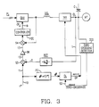
- the current source inverter (CSI) control for a Load Commutated Inverter Induction Motor (LCI/IM) drive is illustrated in block diagram as a direct modification of the circuit of Figure 2.
- a function generator FG is added responding to the reference frequency of lines 10 and 50 and outputting on line 51 a signal representative of the desired power factor angle ⁇ .
- the signal of line 51 is thereafter applied to a delay circuit DL which is interposed upon the series of pulses derived on line 53 from a zero-crossing detector (ZCD) having its input connected to the output lines OL of the inverter.
- ZCD zero-crossing detector
- the signal of line 51 insures that, whatever the load condition and the occurrence of the pulse of line 10 which is imposed by the frequency reference signal f*, firing will occur so that it matches the power factor angle, and the quadrature component of current will exist to prevent the runaway condition.
- the implementation of block FG is according to the afore-stated function F defining the angle ⁇ .
- the angle ⁇ is preprogrammed in a PROM as a function of the reference frequency f* addressing the PROM from line 50.
- the function so implemented is to impose an inverter firing instant that will cause the current impressed on the load to lead the voltage by ⁇ degrees.
- the power factor cos ⁇ is implemented by requiring a delay in the application of the gating pulses to the inverter, thereby forcing a quadrature component of the current to be formed which will reestablish a balance between the capacitive current and the magnetizing current within the current-sourced inverter model.
- the added loop including function generator FG and the power factor angle controlled delay DL, has been added to correct the train of inverter gating pulses, normally received from the zero-crossing detector ZCD by line 53.
Landscapes
- Engineering & Computer Science (AREA)
- Power Engineering (AREA)
- Control Of Ac Motors In General (AREA)
- Inverter Devices (AREA)
- Control Of Motors That Do Not Use Commutators (AREA)
Applications Claiming Priority (2)
| Application Number | Priority Date | Filing Date | Title |
|---|---|---|---|
| US07/249,737 US4833389A (en) | 1988-09-26 | 1988-09-26 | Current source inverter control system for load commutated induction motor drive |
| US249737 | 1988-09-26 |
Publications (2)
| Publication Number | Publication Date |
|---|---|
| EP0361834A2 true EP0361834A2 (de) | 1990-04-04 |
| EP0361834A3 EP0361834A3 (de) | 1991-10-23 |
Family
ID=22944779
Family Applications (1)
| Application Number | Title | Priority Date | Filing Date |
|---|---|---|---|
| EP19890309735 Withdrawn EP0361834A3 (de) | 1988-09-26 | 1989-09-25 | Regelsystem für netzseitigen Stromrichter für einen lastgeführten Induktionsmotorenantrieb |
Country Status (3)
| Country | Link |
|---|---|
| US (1) | US4833389A (de) |
| EP (1) | EP0361834A3 (de) |
| CA (1) | CA1292272C (de) |
Families Citing this family (12)
| Publication number | Priority date | Publication date | Assignee | Title |
|---|---|---|---|---|
| CN1035709C (zh) * | 1989-07-27 | 1997-08-20 | 精工爱普生株式会社 | 电压型脉宽调制变流/逆变器系统及其控制过程 |
| JP3232431B2 (ja) * | 1995-09-08 | 2001-11-26 | 株式会社日立製作所 | 電力変換装置 |
| US8030791B2 (en) * | 2008-07-31 | 2011-10-04 | Rockwell Automation Technologies, Inc. | Current source converter-based wind energy system |
| US8217618B2 (en) * | 2009-02-20 | 2012-07-10 | The Hong Kong Polytechnic University | Energy-saving controller for three-phase induction motors |
| US8587160B2 (en) * | 2009-09-04 | 2013-11-19 | Rockwell Automation Technologies, Inc. | Grid fault ride-through for current source converter-based wind energy conversion systems |
| US8816625B2 (en) | 2011-10-27 | 2014-08-26 | Rockwell Automation Technologies, Inc. | Integrated regenerative AC drive with solid state precharging |
| US9041234B2 (en) | 2012-03-26 | 2015-05-26 | Rockwell Automation Technologies, Inc. | Double fed induction generator (DFIG) converter and method for improved grid fault ridethrough |
| US9083274B2 (en) | 2013-04-08 | 2015-07-14 | Rockwell Automation Technologies, Inc. | Power stage precharging and dynamic braking apparatus for multilevel inverter |
| US9041327B2 (en) | 2013-06-12 | 2015-05-26 | Rockwell Automation Technologies, Inc. | Method and apparatus for overvoltage protection and reverse motor speed control for motor drive power loss events |
| US9787210B2 (en) | 2015-01-14 | 2017-10-10 | Rockwell Automation Technologies, Inc. | Precharging apparatus and power converter |
| US9847733B2 (en) | 2016-05-12 | 2017-12-19 | Rockwell Automation Technologies, Inc. | Power conversion system with DC bus regulation for abnormal grid condition ride through |
| US11025052B2 (en) | 2018-01-22 | 2021-06-01 | Rockwell Automation Technologies, Inc. | SCR based AC precharge protection |
Family Cites Families (10)
| Publication number | Priority date | Publication date | Assignee | Title |
|---|---|---|---|---|
| US4315305A (en) * | 1979-09-12 | 1982-02-09 | Borg-Warner Corporation | Controlled D-C power supply |
| US4481457A (en) * | 1981-03-06 | 1984-11-06 | General Electric Company | Method for providing adaptive control of variable speed AC motor drives |
| US4420719A (en) * | 1981-12-23 | 1983-12-13 | General Electric Company | Cross-tied current regulator for load commutated inverter drives |
| US4426611A (en) * | 1982-04-28 | 1984-01-17 | General Electric Company | Twelve pulse load commutated inverter drive system |
| FR2542944B1 (fr) * | 1983-03-14 | 1985-06-28 | Cem Comp Electro Mec | Procede et dispositif de commande d'un moteur asynchrone a vitesse variable alimente par un commutateur de courant |
| US4620296A (en) * | 1984-11-29 | 1986-10-28 | Dana Corporation | Protection system for immunizing a controlled d-c power supply against a-c line voltage interruptions |
| US4600874A (en) * | 1985-01-26 | 1986-07-15 | General Electric Company | Excitation current control for induction motor drive using load commutated inverter circuit |
| US4697131A (en) * | 1985-12-11 | 1987-09-29 | Westinghouse Electric Corp. | Voltage source inverter and variable frequency, constant voltage AC motor drive embodying the same |
| SE452934B (sv) * | 1986-04-14 | 1987-12-21 | Elfi Innovationer | Sett och anordning for att driva en via en vexelriktare varvtalsreglerad asynkronmotor |
| US4713743A (en) * | 1987-02-06 | 1987-12-15 | Westinghouse Electric Corp. | Load-commutated inverter and synchronous motor drive embodying the same |
-
1988
- 1988-09-26 US US07/249,737 patent/US4833389A/en not_active Expired - Fee Related
-
1989
- 1989-08-31 CA CA000609947A patent/CA1292272C/en not_active Expired - Lifetime
- 1989-09-25 EP EP19890309735 patent/EP0361834A3/de not_active Withdrawn
Also Published As
| Publication number | Publication date |
|---|---|
| CA1292272C (en) | 1991-11-19 |
| EP0361834A3 (de) | 1991-10-23 |
| US4833389A (en) | 1989-05-23 |
Similar Documents
| Publication | Publication Date | Title |
|---|---|---|
| AU2008227057B2 (en) | Motor drive using flux adjustment to control power factor | |
| US6262555B1 (en) | Apparatus and method to generate braking torque in an AC drive | |
| US4740738A (en) | Reluctance motor control system and method | |
| US4962339A (en) | Pole-tying current control apparatus | |
| US4227138A (en) | Reversible variable frequency oscillator for smooth reversing of AC motor drives | |
| Boldea et al. | Torque vector control (TVC)-a class of fast and robust torque-speed and position digital controllers for electric drives | |
| US4885518A (en) | Induction motor torque/flux control system | |
| US4904919A (en) | Dual mode control of a PWM motor drive for current limiting | |
| Holtz et al. | Field-oriented asynchronous pulsewidth modulation for high performance ac machine drives operating at low switching frequency | |
| US4511835A (en) | Voltage-controlled, inverter-motor system | |
| EP0000530A1 (de) | Verfahren und Schaltung zur rückgekoppelten Regelung von Wechselstrom-motoren zwecks Verminderung des pulsierenden Drehmoments | |
| Nonaka et al. | A PWM GTO current source converter-inverter system with sinusoidal inputs and outputs | |
| EP0361834A2 (de) | Regelsystem für netzseitigen Stromrichter für einen lastgeführten Induktionsmotorenantrieb | |
| DK210180A (da) | Belastningstilstandsregulering af en vekselretterfoedet asynkronmaskine | |
| CA1298611C (en) | Load commutated inverter (lci) induction motor drive | |
| US5479081A (en) | AC motor controller with voltage margin adjustment | |
| KR880002315A (ko) | 전동기의 속도 제어장치 | |
| CN114759812B (zh) | 以高开关频率操作的逆变器及用于操作逆变器的方法 | |
| WO1990007818A3 (en) | Low distortion control for a vscf generating system | |
| US5359272A (en) | Sensorless drive control and method for doubly-fed reluctance motor | |
| EP0344370B1 (de) | Regelung eines Wechselstrommotors, insbesondere bei niedrigen Geschwindigkeiten | |
| US4420719A (en) | Cross-tied current regulator for load commutated inverter drives | |
| US4791340A (en) | Induction motor drive arrangement | |
| RU2115218C1 (ru) | Способ управления элетроприводом переменного тока | |
| Liu et al. | Modeling and performance of a static frequency converter starting a 300 MVA synchronous machine |
Legal Events
| Date | Code | Title | Description |
|---|---|---|---|
| PUAI | Public reference made under article 153(3) epc to a published international application that has entered the european phase |
Free format text: ORIGINAL CODE: 0009012 |
|
| AK | Designated contracting states |
Kind code of ref document: A2 Designated state(s): DE FR GB |
|
| PUAL | Search report despatched |
Free format text: ORIGINAL CODE: 0009013 |
|
| AK | Designated contracting states |
Kind code of ref document: A3 Designated state(s): DE FR GB |
|
| 17P | Request for examination filed |
Effective date: 19920416 |
|
| STAA | Information on the status of an ep patent application or granted ep patent |
Free format text: STATUS: THE APPLICATION HAS BEEN WITHDRAWN |
|
| 18W | Application withdrawn |
Withdrawal date: 19920623 |