EP0361846A2 - Soupape de commande de la vitesse de ralenti pour moteur et méthode pour améliorer son fonctionnement - Google Patents
Soupape de commande de la vitesse de ralenti pour moteur et méthode pour améliorer son fonctionnement Download PDFInfo
- Publication number
- EP0361846A2 EP0361846A2 EP89309758A EP89309758A EP0361846A2 EP 0361846 A2 EP0361846 A2 EP 0361846A2 EP 89309758 A EP89309758 A EP 89309758A EP 89309758 A EP89309758 A EP 89309758A EP 0361846 A2 EP0361846 A2 EP 0361846A2
- Authority
- EP
- European Patent Office
- Prior art keywords
- force
- valve
- hollow shaft
- control valve
- plunger
- Prior art date
- Legal status (The legal status is an assumption and is not a legal conclusion. Google has not performed a legal analysis and makes no representation as to the accuracy of the status listed.)
- Withdrawn
Links
- 238000000034 method Methods 0.000 title claims description 15
- 230000007423 decrease Effects 0.000 description 10
- 238000002485 combustion reaction Methods 0.000 description 3
- 238000010586 diagram Methods 0.000 description 3
- 230000000694 effects Effects 0.000 description 3
- 230000006835 compression Effects 0.000 description 2
- 238000007906 compression Methods 0.000 description 2
- 230000008014 freezing Effects 0.000 description 2
- 238000007710 freezing Methods 0.000 description 2
- 239000000470 constituent Substances 0.000 description 1
- 239000010687 lubricating oil Substances 0.000 description 1
- 238000011144 upstream manufacturing Methods 0.000 description 1
Images
Classifications
-
- F—MECHANICAL ENGINEERING; LIGHTING; HEATING; WEAPONS; BLASTING
- F02—COMBUSTION ENGINES; HOT-GAS OR COMBUSTION-PRODUCT ENGINE PLANTS
- F02M—SUPPLYING COMBUSTION ENGINES IN GENERAL WITH COMBUSTIBLE MIXTURES OR CONSTITUENTS THEREOF
- F02M35/00—Combustion-air cleaners, air intakes, intake silencers, or induction systems specially adapted for, or arranged on, internal-combustion engines
-
- F—MECHANICAL ENGINEERING; LIGHTING; HEATING; WEAPONS; BLASTING
- F02—COMBUSTION ENGINES; HOT-GAS OR COMBUSTION-PRODUCT ENGINE PLANTS
- F02M—SUPPLYING COMBUSTION ENGINES IN GENERAL WITH COMBUSTIBLE MIXTURES OR CONSTITUENTS THEREOF
- F02M3/00—Idling devices for carburettors
- F02M3/06—Increasing idling speed
- F02M3/07—Increasing idling speed by positioning the throttle flap stop, or by changing the fuel flow cross-sectional area, by electrical, electromechanical or electropneumatic means, according to engine speed
- F02M3/075—Increasing idling speed by positioning the throttle flap stop, or by changing the fuel flow cross-sectional area, by electrical, electromechanical or electropneumatic means, according to engine speed the valve altering the fuel conduit cross-section being a slidable valve
Definitions
- This invention relates to an idling engine speed control valve for controlling the idling of an internal combustion engine for an automobile, and more particularly to a method of improving the characteristics of an idling engine speed control valve with respect to the time of the starting of an engine.
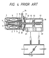
- FIG 4 of the accompanying drawings is a sectional view of a conventional idling engine speed control valve.
- a plunger 1 when an electric current is applied to an electromagnetic coil 6 (which will hereinafter be referred to as a coil), a plunger 1 is moved to the left (as viewed in Figure 4).
- a shaft 2 is fixed to the plunger 1 and urged to the right (as shown in Figure 4) by a spring 7.
- a core 3 for the coil 6 supports an adjusting screw 4 for restricting the stroke of the shaft 2, the screw head being sealed in a bore by an O-ring 5.
- the right hand end surface (shown in Figure 4) of the plunger 1 is concave and is provided with a pilot valve seat 7 via the shaft 2.
- a spring 8 urges the plunger 1 to the left in Figure 4.
- a hollow shaft 10 is provided so that the hollow shaft 10 can be slid coaxially with the plunger 1.
- the right hand end in Figure 4 of the hollow shaft 10 is disposed in a chamber 22 of a body 17, and the chamber 22 communicates with the portion of a throttle unit in a carburetor located on the downstream side of a throttle valve 101.
- a guide 18 is provided for the hollow shaft 10.
- a main valve 13 is fixed on the hollow shaft 10 and positioned between the chamber 22 and a chamber 21 which communicates with the portion of the throttle unit which is on the upstream side of the throttle valve 101.
- the hollow shaft 10 also supports a diaphragm 11 via a plate 12, and the diaphragm 11 defines the chamber 21 and a diaphragm chamber 20.
- the diaphragm chamber 20 communicates with the atmosphere via an orifice 14.
- a pilot valve 15 is formed on the hollow shaft 10.
- the pilot valve 15 is positioned in the diaphragm chamber 20 and opposed to the pilot valve seat 9.
- a difference between the pressures on the front and rear sides of the main valve 13 occurs due to the suction vacuum of the engine applied to the chamber 22 on the air discharge side, and constitutes a difference between the pressures in the chambers 21, 22.
- This differential pressure is about 500mmHg in a normal idling condition, and works as a force for closing the main valve 13.
- the hollow shaft 10 and main valve 13 mounted fixedly thereon are driven by the plunger 1 as the driving force of the plunger 1 is increased doubly by the force of the differential pressure applied to the diaphragm 11.
- starting engine speed is low, for example, under low-temperature conditions, for example 0°C or less
- a sufficiently large difference does not occur between the pressures in the chamber 21 and diaphragm chamber 20 in this prior art valve. Therefore the force for opening the main valve 13 produced by the diaphragm 11 is not sufficient and it becomes impossible to obtain desired idling engine speed control characteristics.
- An object of the present invention is to provide a method of improving the characteristics of an idling engine speed control valve so as to eliminate the difficulties in starting an engine under low-temperature conditions, i.e. so as to enable an engine to be suitably started under low-temperature conditions, e.g. at or below 0°C; and an idling engine speed control valve having improved characteristics with respect to the starting of an engine under low-temperature conditions.
- a valve opening force is applied to a main valve in an idling engine speed control valve.
- This force may be permanent and can be constant but it is not, of course, so large that it disturbs the normal operation of each part but is large enough to ensure that the valve opening force is sufficient at the time of starting the engine under low-temperature conditions.
- Japanese Patent Laid-open No. Japanese Patent Laid-open No.
- the method according to the present invention consists of the step of applying a small force (auxiliary valve opening force) to the main valve in the valve opening direction constantly and one-sidedly.
- An idling engine speed control valve according to the present invention developed for practicing the above-described method according to the present invention is provided with a means (for example, a coiled compression spring) for applying a force to the main valve in the valve opening direction.
- a means for example, a coiled compression spring
- This valve opening force is a one-sided auxiliary force, and this valve opening force applying means does not have a structure for restricting the position of the main valve by a force balancing operation.
- an auxiliary valve opening force is applied to the main valve by, for example, a coiled compression spring exerting a constant force. Accordingly, any diminution of the valve opening force when the engine is started at a lower temperature is overcome, and a proper flow rate of combustion air can be obtained. This enables a proper fuel-air ratio to be obtained, and a rate of success of an engine starting operation to be markedly improved.
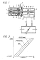
- Figure 1 is a sectional view of an embodiment of the idling engine speed control valve according to the present invention constructed by utilizing the valve characteristic improving method in accordance with the present invention.
- the embodiment of Figure 1 is an improvement on the prior art conventional example shown in Figure 4, which improvement is obtained by applying the concept of the present invention thereto.
- the parts, which are designated by the same reference numerals as those used for the prior art, of this embodiment represent constituent parts identical with or similar to those of the conventional example. Accordingly, the descriptions of the parts of this embodiment, which are identical with or similar to those shown in Figure 4, will be omitted.
- valve opening force in an engine starting operation under the low-temperature conditions tends to diminish for the above-mentioned reasons but, when the diminution of the valve opening force is a low-temperature engine starting operationis compensated by the force of the coiled spring 16a, the main valve 13 can be opened even in an engine starting operation under such low-temperature conditions.
- the spring 61a exerts a permanent force which may be arranged to be constant.
- Figure 2 is a valve characteristic diagram in which the rate of supplying an electric current to the coil 6 in the Figure 1 embodiment is taken in the direction of the horizontal axis with the valve opening stroke concerning the main valve 13 taken in the direction of the vertical axis.
- This diagram shows three lines with the vacuum on the downstream side of the throttle valve used as a parameter.
- This characteristic diagram clearly shows that, if an electric current is applied to the coil 6 in the idling engine speed control valve in this invention, the main valve is opened provided there is some current flow even when the differential suction pressure is ultimately low (OPa). Therefore, a starting operation can be carried out even when the temperature is low, and the shortage of the flow rate of suction air, which results in failure in a starting operation, can be prevented.
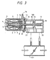
- Figure 3 shows a further embodiment, different from the above-described embodiment.
- the differences between the first embodiment ( Figure 1) and the embodiment of Figure 3 reside in that a coiled spring 16b is inserted in a compressed state between the body 17 and diaphragm 11 (plate 12) supporting the diaphragm 11 to be exact).
- This embodiment also enables the same operation and effect as in the previously-described embodiment to be obtained.
- valve characteristic improving method As described above, when the idling engine speed control valve according to the present invention is constructed by utilizing the valve characteristic improving method according to the present invention, suitable valve characteristics are obtained in a starting operation under low-temperature conditions, and a proper flow rate of suction air even under the low-temperature starting conditions. Therefore, a proper fuel-air ratio is obtained, and a failure in a starting operation, which is ascribed to an improper fuel-air ratio, can be prevented.
Landscapes
- Engineering & Computer Science (AREA)
- Chemical & Material Sciences (AREA)
- Combustion & Propulsion (AREA)
- Mechanical Engineering (AREA)
- General Engineering & Computer Science (AREA)
- Control Of Throttle Valves Provided In The Intake System Or In The Exhaust System (AREA)
- Magnetically Actuated Valves (AREA)
- Fluid-Driven Valves (AREA)
Applications Claiming Priority (2)
| Application Number | Priority Date | Filing Date | Title |
|---|---|---|---|
| JP239027/88 | 1988-09-26 | ||
| JP63239027A JPH0713504B2 (ja) | 1988-09-26 | 1988-09-26 | 機関のアイドル回転数制御弁の弁特性改善方法 |
Publications (2)
| Publication Number | Publication Date |
|---|---|
| EP0361846A2 true EP0361846A2 (fr) | 1990-04-04 |
| EP0361846A3 EP0361846A3 (fr) | 1990-06-13 |
Family
ID=17038795
Family Applications (1)
| Application Number | Title | Priority Date | Filing Date |
|---|---|---|---|
| EP89309758A Withdrawn EP0361846A3 (fr) | 1988-09-26 | 1989-09-26 | Soupape de commande de la vitesse de ralenti pour moteur et méthode pour améliorer son fonctionnement |
Country Status (3)
| Country | Link |
|---|---|
| EP (1) | EP0361846A3 (fr) |
| JP (1) | JPH0713504B2 (fr) |
| KR (1) | KR900005056A (fr) |
Family Cites Families (3)
| Publication number | Priority date | Publication date | Assignee | Title |
|---|---|---|---|---|
| DE3328950A1 (de) * | 1983-08-11 | 1985-02-28 | Vdo Adolf Schindling Ag, 6000 Frankfurt | Ventilanordnung |
| KR870006308A (ko) * | 1985-12-10 | 1987-07-10 | 미타 가쓰시게 | 자동차용 아이들회전 제어장치 |
| JPH0774629B2 (ja) * | 1987-10-12 | 1995-08-09 | 株式会社日立製作所 | アイドル回転制御装置 |
-
1988
- 1988-09-26 JP JP63239027A patent/JPH0713504B2/ja not_active Expired - Fee Related
-
1989
- 1989-09-23 KR KR1019890013727A patent/KR900005056A/ko not_active Withdrawn
- 1989-09-26 EP EP89309758A patent/EP0361846A3/fr not_active Withdrawn
Also Published As
| Publication number | Publication date |
|---|---|
| EP0361846A3 (fr) | 1990-06-13 |
| JPH0713504B2 (ja) | 1995-02-15 |
| KR900005056A (ko) | 1990-04-13 |
| JPH0286960A (ja) | 1990-03-27 |
Similar Documents
| Publication | Publication Date | Title |
|---|---|---|
| US5280775A (en) | Fuel vapor control valve device | |
| US4377146A (en) | Vaporized fuel controller for a carburetor | |
| US4796592A (en) | Fuel injection pump for internal combustion engines | |
| US4434775A (en) | Apparatus for controlling pressurized air supply to engines | |
| EP0361846A2 (fr) | Soupape de commande de la vitesse de ralenti pour moteur et méthode pour améliorer son fonctionnement | |
| US6581573B2 (en) | Compound electromagnetic valve, high pressure pump and apparatus for controlling high pressure pump | |
| EP0012567B1 (fr) | Réglage de l'écoulement du carburant d'un système d'injection de carburant | |
| US4344406A (en) | Fuel saver | |
| JP3742996B2 (ja) | 燃料供給装置 | |
| US4596121A (en) | Control apparatus for selectively supplying electricity | |
| US4449500A (en) | Injection compensator for fuel injection pump | |
| US20040238773A1 (en) | Controlled leakage hydraulic damper | |
| US6860254B2 (en) | Carburetor | |
| JP2669820B2 (ja) | 内燃機関の燃焼室内の燃料分布を制御する方法及び燃料噴射装置 | |
| US4282840A (en) | Internal combustion engine with altitude compensation device | |
| EP0404347B1 (fr) | Regulateur de pression | |
| JP4078779B2 (ja) | 燃料噴射弁 | |
| US3768450A (en) | Automatic idle speed controller | |
| KR100304311B1 (ko) | 엘피지레귤레이터 | |
| US4211197A (en) | Compressive pressure augmentation device | |
| JP3273325B2 (ja) | 燃料噴射式エンジンの燃料圧力調整装置 | |
| US4736720A (en) | Idling speed control system for internal combustion engines | |
| EP1193387B1 (fr) | Injecteur à gaz | |
| JPH062619A (ja) | エンジンの気体燃料供給装置 | |
| JP2791432B2 (ja) | エンジンの燃料供給装置 |
Legal Events
| Date | Code | Title | Description |
|---|---|---|---|
| PUAI | Public reference made under article 153(3) epc to a published international application that has entered the european phase |
Free format text: ORIGINAL CODE: 0009012 |
|
| 17P | Request for examination filed |
Effective date: 19891024 |
|
| AK | Designated contracting states |
Kind code of ref document: A2 Designated state(s): DE FR GB |
|
| PUAL | Search report despatched |
Free format text: ORIGINAL CODE: 0009013 |
|
| AK | Designated contracting states |
Kind code of ref document: A3 Designated state(s): DE FR GB |
|
| 17Q | First examination report despatched |
Effective date: 19911010 |
|
| STAA | Information on the status of an ep patent application or granted ep patent |
Free format text: STATUS: THE APPLICATION IS DEEMED TO BE WITHDRAWN |
|
| 18D | Application deemed to be withdrawn |
Effective date: 19920421 |