EP0361868A2 - Flüssigkristallanzeigevorrichtung - Google Patents
Flüssigkristallanzeigevorrichtung Download PDFInfo
- Publication number
- EP0361868A2 EP0361868A2 EP89309793A EP89309793A EP0361868A2 EP 0361868 A2 EP0361868 A2 EP 0361868A2 EP 89309793 A EP89309793 A EP 89309793A EP 89309793 A EP89309793 A EP 89309793A EP 0361868 A2 EP0361868 A2 EP 0361868A2
- Authority
- EP
- European Patent Office
- Prior art keywords
- led
- current
- lcd
- voltage
- circuit
- Prior art date
- Legal status (The legal status is an assumption and is not a legal conclusion. Google has not performed a legal analysis and makes no representation as to the accuracy of the status listed.)
- Ceased
Links
- 239000004973 liquid crystal related substance Substances 0.000 title claims abstract description 17
- 230000001105 regulatory effect Effects 0.000 claims abstract description 20
- 238000010276 construction Methods 0.000 description 9
- 238000010586 diagram Methods 0.000 description 5
- 238000000034 method Methods 0.000 description 3
- QTBSBXVTEAMEQO-UHFFFAOYSA-M Acetate Chemical compound CC([O-])=O QTBSBXVTEAMEQO-UHFFFAOYSA-M 0.000 description 1
- 238000012369 In process control Methods 0.000 description 1
- 230000033228 biological regulation Effects 0.000 description 1
- 239000003990 capacitor Substances 0.000 description 1
- 238000006243 chemical reaction Methods 0.000 description 1
- 230000000295 complement effect Effects 0.000 description 1
- 230000001276 controlling effect Effects 0.000 description 1
- 230000007423 decrease Effects 0.000 description 1
- 238000004880 explosion Methods 0.000 description 1
- 238000010965 in-process control Methods 0.000 description 1
- 238000004886 process control Methods 0.000 description 1
- 230000001681 protective effect Effects 0.000 description 1
Images

Classifications
-
- G—PHYSICS
- G09—EDUCATION; CRYPTOGRAPHY; DISPLAY; ADVERTISING; SEALS
- G09F—DISPLAYING; ADVERTISING; SIGNS; LABELS OR NAME-PLATES; SEALS
- G09F9/00—Indicating arrangements for variable information in which the information is built-up on a support by selection or combination of individual elements
- G09F9/30—Indicating arrangements for variable information in which the information is built-up on a support by selection or combination of individual elements in which the desired character or characters are formed by combining individual elements
- G09F9/35—Indicating arrangements for variable information in which the information is built-up on a support by selection or combination of individual elements in which the desired character or characters are formed by combining individual elements being liquid crystals
Definitions
- This invention relates to a loop-powered backlit liquid crystal display and more particularly to a light emitting diode connected in series with an instrumentation loop for illuminating the display of an indicating meter.
- Liquid crystal display devices are becoming evermore widely used in the process control industry.
- meters with liquid crystal displays are often self-powered from the instrumentation loops used to transmit process parameters such as temperature, pressure and flow rates.
- the process parameters are commonly sensed by transducers such as flow transmitters which transmit current proportional to the sensed process parameter.
- the amount of current transmitted typically 4-20 milliamps, is supplied to the loop and is calibrated by the meter which measures the voltage across a sensing resistor to indicate the measured value.
- the LCD meters are used in areas where ambient light is insufficient for proper viewing or they may be encased in explosion proof or protective housings which limit the ambient light available to the LCD. In such applications independent lighting from a separate power source is necessary in order to illuminate the display.
- a truly effective self-powered backlit liquid crystal display can be made by including a light emitting diode (LED) in the instrumentation loop proximate to the liquid crystal display for illuminating the display when ambient light is insufficient to permit the display from being read,
- the LED can be powered by a voltage inverter connected in series with the instrumentation loop for providing the increased voltage necessary to drive the LED without increasing the voltage burden on the instrumentation loop.
- This invention features a loop-powered, backlit liquid crystal display (LCD) which includes a current instrumentation loop for providing a current representative of a value to be measured and an LCD for displaying the measured value.
- a light emitting diode (LED) circuit having an LED is disposed proximate to the LCD and is interconnected with, and driven by, the current of the current instrumentation loop for backlighting the LCD.
- biasing means are interconnected in series with the LED to form a bias circuit, and a current regulating amplifier is interconnected with the bias circuit and operated by the biasing means to regulate the current through the LED.
- the biasing means may include a second LED.
- the LED circuit includes a voltage inverter circuit interconnected with the LED, the LED being connected with its anode to the positive terminal of the voltage inverter and its cathode connected to the negative terminal of the voltage inverter for increasing the voltage used to drive the LED.
- the LED circuit can further include a second LED in series with the first LED; the first and second LEDs are interconnected in parallel with the voltage inverter circuit.
- the loop-powered, backlit LCD includes a second LED in series with the first LED and biasing means interconnected in series between the LEDs to form a bias circuit.
- the bias circuit is connected at one end to the positive terminal of a voltage inverter and at the other end to the negative terminal of the voltage inverter.
- the LEDs are disposed proximate to the LCD.
- a light diffusing element can be disposed between the LEDs and the LCD for diffusely illuminating the LCD.
- Interconnected with the bias circuit is a current regulating amplifier which is operated by the biasing means to regulate current through the LEDs.
- a voltage inverter circuit interconnected with the bias circuit increases the voltage used to drive the LEDs without increasing the voltage burden on the instrumentation loop.
- the voltage used to drive the LCD is proportional to the current in the instrumentation loop and is developed across a resistor connected in series with the LED circuit. That voltage is sensed by a loop-powered meter for driving the LCD to display a measured value.
- a loop powered, backlit LCD includes terminal means for receiving current representative of a value to be measured, an LCD for displaying the measured value, and a light-emitting diode (LED) circuit which includes an LED disposed proximate to the LCD and interconnected, and driven by, the current for backlighting the LCD.
- the loop-powered, backlit liquid crystal display further includes transmitter means connected to the terminal means for generating the current representative of the value to be measured.
- the LED circuit also includes biasing means interconnected in series with the LED to form a bias circuit and a current regulating amplifier connected in parallel with the bias circuit. The current regulating amplifier is operated by the bias level at the junction of the LED and the biasing means for regulating the current through the LED.
- a voltage inverter circuit is also interconnected with the bias circuit, the bias circuit has one end connected to the positive terminal of the voltage inverter and the other end connected to the negative terminal of the voltage inverter for providing an increased voltage which is used to drive the LED without increasing the voltage burden on the instrument loop.
- the biasing means may include a resistor and a second LED.
- a second resistor is placed in series with the current regulating amplifier and the voltage inverter.
- a loop-powered meter interconnected with the second resistor senses the voltage developed across the second resistor for driving the LCD to display a measured value.
- the loop-powered meter with a backlit liquid crystal display may be accomplished by a light emitting diode (LED) circuit which is used to backlight a liquid crystal display (LCD).
- the LED circuit is interconnected with and driven by a current instrumentation loop used to drive the meter.
- the LED circuit includes at least one LED disposed proximate to the LCD for illuminating the display.
- the LED is preferably a high light output LED such as a GaAsP/GaP.
- a light-diffusing element such as a flat sheet of frosted acetate, can be disposed between the LED and the LCD to evenly illuminate the LCD.
- the LED circuit includes a resistor interconnected in series between two LEDs to form a biasing circuit.
- the brightness of the LED and the amount of current flowing through the LED is regulated by a current regulating amplifier which is connected in parallel and biased by the biasing circuit.
- the current regulating amplifier is a transistor having a high beta value such as 100.
- a DC to DC voltage converter such as an ICL 7660 is connected as an inverter in parallel with the voltage divider for increasing the voltage used to drive the LEDs without burdening the voltage available on the loop.
- a sensing resistor placed in series with the LED circuit develops a voltage that is proportional to the current in the loop. This voltage is measured by a self-powered meter which displays the measured value on the LCD.
- the LED circuit consists of one or more LEDs connected across a DC/DC voltage converter.
- the converter operating as an inverter, increases the voltage necessary to drive the LEDs without increasing the voltage burden on the instrumentation loop.
- the brightness of and current through the LEDs are not controlled by a current regulating amplifier.
- the LED circuit includes an LED placed proximate to the LCD and driven by the instrumentation loop.
- the current through the LED can be regulated by a current regulating amplifier.
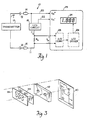
- a loop-powered, backlit LCD circuit 10, Fig. 1 includes an instrument current loop 11, which consists of an LED circuit 18 and a sensing resistor R s connected in parallel with a transmitter 12 at terminals 14 and 16.
- Current I is produced by transmitter 12 and is fed to LED circuit 18 for providing voltage to power meter 25 via lines 20 and 22, and for developing a voltage V in across a sensing resistor R s , which is proportional to the current I.
- This voltage is converted to digital by an analog to digital converter 26 which drives an LCD driver 28 for displaying the measured value on LCD 24.
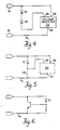
- the LED circuit 18, shown in greater detail in Fig. 2, includes a bias circuit 30 which consists of bias means, resistor R1, placed between two LEDs D1 and D2.
- One end of the biasing circuit is connected to the positive terminal 14 of the current loop and to positive terminal 32 of a voltage inverter 34; the other end is connected to output terminal 36 of voltage inverter 34.
- the ground terminal 35 of voltage inverter 34 is connected to sensing resistor R S .
- Voltage inverter 34 performs a voltage conversion of the voltage applied across its input terminal and ground terminal, resulting in a complementary output voltage -V m at its output terminal 36.
- the negative voltage at output terminal 36 is sufficiently negative to drive LEDs D1 and D2.
- the negative voltage -V m at output terminal 36 is also used in conjunction with positive terminal 14 for supplying power to drive A/D converter 26 and LCD driver 28 of voltage meter 25, Fig. 1.
- a transistor Q1 is connected in parallel with voltage inverter 34 to regulate the brightness of LEDs D1 and D2 by controlling the current through bias circuit 30.
- Transistor Q1 is biased by connecting its base at junction b between LED D1 and resistor R1.
- Resistor R1 establishes the voltage at the base of transistor Q1 and thus the current level through diodes D1 and D2.
- a reverse current protection diode D3 is connected in parallel with transistor Q1 to protect the LED circuit 18 from reverse current conditions in the instrumentation current loop.
- Bypass capacitors C1 and C2 are also connected between output terminal 36 of voltage inverter 34 and the sensing resistor R s and between positive terminal 14 of the current loop and sensing resistor R s , respectively.
- V ce V fd + V be (1)
- Formula (2) is a simplified equation for the collector current of Q1 in terms of base current (I b ) and the current transfer ratio beta ( ⁇ ).
- I c ⁇ I b ⁇ ⁇ 100 (2)
- I4 is the combined current of I1 and I3 plus any current flowing through the digital volt meter from the V m meter supply.
- diodes D1 and D2 are positioned on a printed circuit board 40 such that they extend through a reflective block 42 for illuminating LCD 24.
- a light diffuser 44 is disposed between LCD 24 and reflector block 42 for uniformly distributing light from LEDs D1 and D2 to display 24.
- a backlit LCD circuit that does not regulate LED current can be accomplished by connecting two LEDs in series between the positive terminal 14 of the instrumentation loop and output terminal 36 of voltage inverter 34, as shown in Fig. 4.
- the positive terminal 32 of voltage inverter 34 is connected to the positive terminal 14 of the current instrumentation loop and the ground terminal 35 is connected in such a way as to return the current via R S to the transmitter, not shown.
- LED D1 is placed directly across the positive and negative terminals 14 and 16 of the current instrumentation loop as indicated by a phantom connection 48 in Fig. 5.
- LED D1 is connected to voltage inverter 34 in a similar manner as described above.
- the brightness of a backlit LCD can be controlled by regulating the current through LED D1 as shown in Fig. 6.
- DC to DC voltage converter is not used for increasing the voltage required to drive LED D1.
Landscapes
- Chemical & Material Sciences (AREA)
- Crystallography & Structural Chemistry (AREA)
- Physics & Mathematics (AREA)
- General Physics & Mathematics (AREA)
- Engineering & Computer Science (AREA)
- Theoretical Computer Science (AREA)
- Measurement Of Current Or Voltage (AREA)
- Liquid Crystal (AREA)
- Control Of Indicators Other Than Cathode Ray Tubes (AREA)
- Liquid Crystal Display Device Control (AREA)
- Devices For Indicating Variable Information By Combining Individual Elements (AREA)
Applications Claiming Priority (2)
| Application Number | Priority Date | Filing Date | Title |
|---|---|---|---|
| US07/249,970 US4959642A (en) | 1988-09-27 | 1988-09-27 | Instrumentation loop-powered backlit liquid crystal display |
| US249970 | 1988-09-27 |
Publications (2)
| Publication Number | Publication Date |
|---|---|
| EP0361868A2 true EP0361868A2 (de) | 1990-04-04 |
| EP0361868A3 EP0361868A3 (de) | 1992-04-01 |
Family
ID=22945776
Family Applications (1)
| Application Number | Title | Priority Date | Filing Date |
|---|---|---|---|
| EP19890309793 Ceased EP0361868A3 (de) | 1988-09-27 | 1989-09-26 | Flüssigkristallanzeigevorrichtung |
Country Status (3)
| Country | Link |
|---|---|
| US (1) | US4959642A (de) |
| EP (1) | EP0361868A3 (de) |
| JP (1) | JPH0625920B2 (de) |
Cited By (1)
| Publication number | Priority date | Publication date | Assignee | Title |
|---|---|---|---|---|
| EP0615372A1 (de) * | 1993-03-08 | 1994-09-14 | Communications Manufacturing Company | Verbesserter Datenterminal für Fernsprechschaltungen |
Families Citing this family (24)
| Publication number | Priority date | Publication date | Assignee | Title |
|---|---|---|---|---|
| JPH0384889U (de) * | 1989-12-14 | 1991-08-28 | ||
| CA2067467C (en) * | 1991-05-03 | 1998-01-06 | Roland G. Miller | Display arrangement |
| GB9125331D0 (en) * | 1991-11-28 | 1992-01-29 | Shaye Communications Ltd | Illumination of displays |
| US7310072B2 (en) | 1993-10-22 | 2007-12-18 | Kopin Corporation | Portable communication display device |
| US20010054989A1 (en) * | 1993-10-22 | 2001-12-27 | Matthew Zavracky | Color sequential display panels |
| US5642129A (en) * | 1994-03-23 | 1997-06-24 | Kopin Corporation | Color sequential display panels |
| US6574652B2 (en) | 1994-10-18 | 2003-06-03 | M-I L.L.C. | Intrinsically safe communication and control system for use in hazardous locations including monotoring device with intrinsically safe fluorescent tube backlit |
| US6140987A (en) * | 1996-09-18 | 2000-10-31 | Intellinet, Inc. | User interface for home automation system |
| US5805062A (en) * | 1996-10-21 | 1998-09-08 | Mini-Systems, Inc. | 2-wire optovoltaic loop-powered isolation amplifier with current bootstrapping |
| US7372447B1 (en) | 1996-10-31 | 2008-05-13 | Kopin Corporation | Microdisplay for portable communication systems |
| US6486862B1 (en) * | 1996-10-31 | 2002-11-26 | Kopin Corporation | Card reader display system |
| US6677936B2 (en) | 1996-10-31 | 2004-01-13 | Kopin Corporation | Color display system for a camera |
| US7321354B1 (en) | 1996-10-31 | 2008-01-22 | Kopin Corporation | Microdisplay for portable communication systems |
| US6476784B2 (en) | 1997-10-31 | 2002-11-05 | Kopin Corporation | Portable display system with memory card reader |
| US6909419B2 (en) | 1997-10-31 | 2005-06-21 | Kopin Corporation | Portable microdisplay system |
| US6552704B2 (en) | 1997-10-31 | 2003-04-22 | Kopin Corporation | Color display with thin gap liquid crystal |
| DE19916747A1 (de) * | 1999-04-13 | 2000-10-19 | Mannesmann Vdo Ag | Selbstleuchtende LCD-Anzeigevorrichtung |
| US6608614B1 (en) * | 2000-06-22 | 2003-08-19 | Rockwell Collins, Inc. | Led-based LCD backlight with extended color space |
| US6697130B2 (en) | 2001-01-16 | 2004-02-24 | Visteon Global Technologies, Inc. | Flexible led backlighting circuit |
| US6717559B2 (en) | 2001-01-16 | 2004-04-06 | Visteon Global Technologies, Inc. | Temperature compensated parallel LED drive circuit |
| US7262752B2 (en) * | 2001-01-16 | 2007-08-28 | Visteon Global Technologies, Inc. | Series led backlight control circuit |
| US6930737B2 (en) * | 2001-01-16 | 2005-08-16 | Visteon Global Technologies, Inc. | LED backlighting system |
| TW548617B (en) * | 2002-06-06 | 2003-08-21 | Au Optronics Corp | Apparatus for controlling liquid crystal timing |
| US11133143B2 (en) * | 2018-10-08 | 2021-09-28 | Texas Instruments Incorporated | Integrated power-ground reverse wiring protection circuit |
Family Cites Families (7)
| Publication number | Priority date | Publication date | Assignee | Title |
|---|---|---|---|---|
| US4431966A (en) * | 1981-05-12 | 1984-02-14 | Sangamo Weston, Inc. | Modular backlighted analog/digital instrument display |
| US4438396A (en) * | 1981-07-24 | 1984-03-20 | General Electric Company | Low cost volt/ampere meter with liquid crystal display |
| US4617562A (en) * | 1983-04-11 | 1986-10-14 | Klotz Dell E | Multicolored liquid crystal display |
| US4609914A (en) * | 1984-04-19 | 1986-09-02 | Ultima Electronics, Ltd. | Voltage monitor and alarm for power line |
| US4714983A (en) * | 1985-06-10 | 1987-12-22 | Motorola, Inc. | Uniform emission backlight |
| DE3533862A1 (de) * | 1985-09-23 | 1987-04-02 | Hirschmann Radiotechnik | Schaltungsanordnung zur anzeige der strom- und/oder leistungsaufnahme durch eine elektrische last |
| US4823078A (en) * | 1987-11-16 | 1989-04-18 | Raychem Corporation | Device for A.C. voltage testing using a voltage multiplier and LCD display |
-
1988
- 1988-09-27 US US07/249,970 patent/US4959642A/en not_active Expired - Fee Related
-
1989
- 1989-09-26 JP JP1250381A patent/JPH0625920B2/ja not_active Expired - Lifetime
- 1989-09-26 EP EP19890309793 patent/EP0361868A3/de not_active Ceased
Cited By (1)
| Publication number | Priority date | Publication date | Assignee | Title |
|---|---|---|---|---|
| EP0615372A1 (de) * | 1993-03-08 | 1994-09-14 | Communications Manufacturing Company | Verbesserter Datenterminal für Fernsprechschaltungen |
Also Published As
| Publication number | Publication date |
|---|---|
| JPH02136886A (ja) | 1990-05-25 |
| EP0361868A3 (de) | 1992-04-01 |
| JPH0625920B2 (ja) | 1994-04-06 |
| US4959642A (en) | 1990-09-25 |
Similar Documents
| Publication | Publication Date | Title |
|---|---|---|
| EP0361868A2 (de) | Flüssigkristallanzeigevorrichtung | |
| US6841947B2 (en) | Systems and methods for controlling brightness of an avionics display | |
| US6069448A (en) | LCD backlight converter having a temperature compensating means for regulating brightness | |
| DE10201280B4 (de) | Anzeigeeinheit mit Leuchtdioden-Hintergrundbeleuchtung | |
| US7705541B2 (en) | Light control circuit | |
| US8144087B2 (en) | Color LED driver | |
| US7002546B1 (en) | Luminance and chromaticity control of an LCD backlight | |
| US7978171B2 (en) | Control circuit of area control driving circuit for LED light source and controlling method thereof | |
| US7855708B2 (en) | LED backlight luminance sensing for LCDs | |
| TWI438742B (zh) | 發光裝置與驅動裝置的方法 | |
| US20030230991A1 (en) | LED-based white-light backlighting for electronic displays | |
| US6690121B1 (en) | High precision luminance control for PWM-driven lamp | |
| KR100502772B1 (ko) | 비선형 응답을 제공하는 장치 | |
| US20080088557A1 (en) | Display apparatus and control method thereof | |
| TWI391750B (zh) | 使用於發光設備中之光源單元 | |
| EP0786755A2 (de) | Flüssigkristallanzeige mit Temperatur-kompensierter Spannung | |
| KR101873497B1 (ko) | 발광 다이오드 구동 장치 | |
| CN1971367A (zh) | 面照明光源、亮度校正电路、亮度校正方法和液晶显示器 | |
| JP4559949B2 (ja) | 光源から出射される光を調節するシステム、方法、及び装置 | |
| US20060243893A1 (en) | A light source for lcd back-lit displays utilizing embedded light detectors | |
| CA2119910A1 (en) | Process variable measuring and display device | |
| JP2007095635A (ja) | 表示ディスプレイにおける照明装置の調光制御を行う方法及び装置 | |
| KR101258083B1 (ko) | 온도보상 led 백라이트 구조를 갖는 액정표시장치 | |
| US20110293286A1 (en) | Method for optical data transmission using existing indicator or illumination lamp | |
| US4999543A (en) | Brilliance control circuit for controlling the brilliance of fluorescent display tubes |
Legal Events
| Date | Code | Title | Description |
|---|---|---|---|
| PUAI | Public reference made under article 153(3) epc to a published international application that has entered the european phase |
Free format text: ORIGINAL CODE: 0009012 |
|
| 17P | Request for examination filed |
Effective date: 19891011 |
|
| AK | Designated contracting states |
Kind code of ref document: A2 Designated state(s): BE DE ES FR GB IT LU NL SE |
|
| PUAL | Search report despatched |
Free format text: ORIGINAL CODE: 0009013 |
|
| AK | Designated contracting states |
Kind code of ref document: A3 Designated state(s): BE DE ES FR GB IT LU NL SE |
|
| 17Q | First examination report despatched |
Effective date: 19940506 |
|
| STAA | Information on the status of an ep patent application or granted ep patent |
Free format text: STATUS: THE APPLICATION HAS BEEN REFUSED |
|
| 18R | Application refused |
Effective date: 19950217 |