EP0361890A2 - Zerstörungsfrei Dimensions- und Fehlerkontrolle von Schweissungen an dünnwandigen Rohren - Google Patents
Zerstörungsfrei Dimensions- und Fehlerkontrolle von Schweissungen an dünnwandigen Rohren Download PDFInfo
- Publication number
- EP0361890A2 EP0361890A2 EP89309831A EP89309831A EP0361890A2 EP 0361890 A2 EP0361890 A2 EP 0361890A2 EP 89309831 A EP89309831 A EP 89309831A EP 89309831 A EP89309831 A EP 89309831A EP 0361890 A2 EP0361890 A2 EP 0361890A2
- Authority
- EP
- European Patent Office
- Prior art keywords
- data
- weld
- feature
- weld section
- tube
- Prior art date
- Legal status (The legal status is an assumption and is not a legal conclusion. Google has not performed a legal analysis and makes no representation as to the accuracy of the status listed.)
- Granted
Links
Images




Classifications
-
- G—PHYSICS
- G01—MEASURING; TESTING
- G01N—INVESTIGATING OR ANALYSING MATERIALS BY DETERMINING THEIR CHEMICAL OR PHYSICAL PROPERTIES
- G01N29/00—Investigating or analysing materials by the use of ultrasonic, sonic or infrasonic waves; Visualisation of the interior of objects by transmitting ultrasonic or sonic waves through the object
- G01N29/22—Details, e.g. general constructional or apparatus details
- G01N29/30—Arrangements for calibrating or comparing, e.g. with standard objects
-
- G—PHYSICS
- G01—MEASURING; TESTING
- G01N—INVESTIGATING OR ANALYSING MATERIALS BY DETERMINING THEIR CHEMICAL OR PHYSICAL PROPERTIES
- G01N29/00—Investigating or analysing materials by the use of ultrasonic, sonic or infrasonic waves; Visualisation of the interior of objects by transmitting ultrasonic or sonic waves through the object
- G01N29/04—Analysing solids
- G01N29/11—Analysing solids by measuring attenuation of acoustic waves
-
- G—PHYSICS
- G01—MEASURING; TESTING
- G01N—INVESTIGATING OR ANALYSING MATERIALS BY DETERMINING THEIR CHEMICAL OR PHYSICAL PROPERTIES
- G01N29/00—Investigating or analysing materials by the use of ultrasonic, sonic or infrasonic waves; Visualisation of the interior of objects by transmitting ultrasonic or sonic waves through the object
- G01N29/34—Generating the ultrasonic, sonic or infrasonic waves, e.g. electronic circuits specially adapted therefor
- G01N29/341—Generating the ultrasonic, sonic or infrasonic waves, e.g. electronic circuits specially adapted therefor with time characteristics
- G01N29/343—Generating the ultrasonic, sonic or infrasonic waves, e.g. electronic circuits specially adapted therefor with time characteristics pulse waves, e.g. particular sequence of pulses, bursts
-
- G—PHYSICS
- G01—MEASURING; TESTING
- G01N—INVESTIGATING OR ANALYSING MATERIALS BY DETERMINING THEIR CHEMICAL OR PHYSICAL PROPERTIES
- G01N29/00—Investigating or analysing materials by the use of ultrasonic, sonic or infrasonic waves; Visualisation of the interior of objects by transmitting ultrasonic or sonic waves through the object
- G01N29/44—Processing the detected response signal, e.g. electronic circuits specially adapted therefor
- G01N29/4454—Signal recognition, e.g. specific values or portions, signal events, signatures
-
- G—PHYSICS
- G21—NUCLEAR PHYSICS; NUCLEAR ENGINEERING
- G21C—NUCLEAR REACTORS
- G21C17/00—Monitoring; Testing ; Maintaining
- G21C17/06—Devices or arrangements for monitoring or testing fuel or fuel elements outside the reactor core, e.g. for burn-up, for contamination
-
- G—PHYSICS
- G01—MEASURING; TESTING
- G01N—INVESTIGATING OR ANALYSING MATERIALS BY DETERMINING THEIR CHEMICAL OR PHYSICAL PROPERTIES
- G01N2291/00—Indexing codes associated with group G01N29/00
- G01N2291/02—Indexing codes associated with the analysed material
- G01N2291/028—Material parameters
- G01N2291/02854—Length, thickness
-
- G—PHYSICS
- G01—MEASURING; TESTING
- G01N—INVESTIGATING OR ANALYSING MATERIALS BY DETERMINING THEIR CHEMICAL OR PHYSICAL PROPERTIES
- G01N2291/00—Indexing codes associated with group G01N29/00
- G01N2291/04—Wave modes and trajectories
- G01N2291/044—Internal reflections (echoes), e.g. on walls or defects
-
- G—PHYSICS
- G01—MEASURING; TESTING
- G01N—INVESTIGATING OR ANALYSING MATERIALS BY DETERMINING THEIR CHEMICAL OR PHYSICAL PROPERTIES
- G01N2291/00—Indexing codes associated with group G01N29/00
- G01N2291/26—Scanned objects
- G01N2291/263—Surfaces
- G01N2291/2634—Surfaces cylindrical from outside
-
- G—PHYSICS
- G01—MEASURING; TESTING
- G01N—INVESTIGATING OR ANALYSING MATERIALS BY DETERMINING THEIR CHEMICAL OR PHYSICAL PROPERTIES
- G01N2291/00—Indexing codes associated with group G01N29/00
- G01N2291/26—Scanned objects
- G01N2291/267—Welds
- G01N2291/2675—Seam, butt welding
-
- G—PHYSICS
- G21—NUCLEAR PHYSICS; NUCLEAR ENGINEERING
- G21C—NUCLEAR REACTORS
- G21C17/00—Monitoring; Testing ; Maintaining
- G21C17/02—Devices or arrangements for monitoring coolant or moderator
-
- Y—GENERAL TAGGING OF NEW TECHNOLOGICAL DEVELOPMENTS; GENERAL TAGGING OF CROSS-SECTIONAL TECHNOLOGIES SPANNING OVER SEVERAL SECTIONS OF THE IPC; TECHNICAL SUBJECTS COVERED BY FORMER USPC CROSS-REFERENCE ART COLLECTIONS [XRACs] AND DIGESTS
- Y02—TECHNOLOGIES OR APPLICATIONS FOR MITIGATION OR ADAPTATION AGAINST CLIMATE CHANGE
- Y02E—REDUCTION OF GREENHOUSE GAS [GHG] EMISSIONS, RELATED TO ENERGY GENERATION, TRANSMISSION OR DISTRIBUTION
- Y02E30/00—Energy generation of nuclear origin
- Y02E30/30—Nuclear fission reactors
Definitions
- the present invention relates to a non-destructive inspection method for performing quality assurance examinations of tube welds and to apparatus for performing same.
- a nuclear fuel rod which is comprised of a column of fuel pellets contained in an elongated cladding tube formed of a zirconium alloy. End plugs, also of a zirconium alloy, are welded to the open ends of the tube to seal the pellet column therein. These end plug welds must meet exacting standards of integrity if they are to withstand the high internal pressures developed over the fuel rod life.
- the head end plug weld has been effected as a bead weld, and thus visual inspection was adequate to verify the presence of sufficient weld cross section to withstand the high internal pressures.
- Random end plug weld samples were examined using X-ray radiography at several viewing angles. The resulting radiographs had to be visually examined, and porosities were detectable and measurable only if located in the several view planes. Porosity resolution was limited to pores in excess of a five mil diameter. Other end plug weld samples were destructively examined by metallographic sectioning mainly for the purpose of qualifying the welding process and detecting process excursion.
- This inspection must include measuring the tube wall thickness adjacent the weld, detecting the presence and size of any flaws in the weld, determining the minimum net cross sectional area of the weld, and the extent of weld penetration into the tube open end. These determinations must then be tested against strict quality assurance standards to decide whether the end plug weld is acceptable or rejectable. All of this should be accomplished in a short period of time, e.g., less than thirty seconds, without human intervention in order that quality assurance inspection not pose a production bottleneck.
- a quality assurance method and apparatus for conducting dimensional and flaw inspection of weldments on an automated basis.
- the invention is disclosed in its application to the quality assurance inspection of nuclear fuel cladding tube end plug welds, wherein the end plug welded end of a tube is axially inserted into an ultrasonic inspection station.
- the tube is clamped in a reference position and then rotated while an ultrasonic transducer is translated in a direction parallel to the tube axis to scan the end plug weld in a tightly spiralled scanning pattern.
- the ultrasonic transducer is pulsed at a multiplicity of uniformly angularly spaced data points along each helical scan line of the scanning pattern.
- the echos received at each data point are variously detected to develop tube and weld thickness data, amplitude data indicative of internal features, such as pores, and feature depth data.
- the weld gross cross sectional area of each scan line slice is computed.
- the cross sectional areas of those features included in each slice are substracted from its computed gross cross sectional area to calculate net cross sectional area.
- the minimum slice net cross sectional area is tested against a threshold limit, and the weld is rejected if this limit is not exceeded.
- the thickness data is further analyzed to determine the degree to which the weld has penetrated the tube open. Insufficient weld penetration is yet another basis for weld rejection.
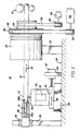
- a weld inspection station is utilized to inspect the integrity of a weld 12 affixing an end plug 14 to the open end of a nuclear fuel cladding tube 16.
- the tube is formed of a suitable metal, such as a zirconium alloy, in lengths typically in excess of ten feet, with an inner diameter on the order of 400 mils and a typical wall thickness of 30 mils.
- the end plug is normally formed of the same metal as the tube.
- the tube is axially propelled, as indicated by arrow 18, end plug end first, into inspection station 10 by suitable means, such as a pinch wheel drive 19. Entry into the inspection station is through the central opening of an air chuck 20 supported by a stand 22 from a table 24.
- An inspection reference position is established by a live centering stop 26 rotatably mounted by bearings 28 carried by a table supported stand 30.
- This stop is formed with an axial bore 26a having a chamferred entry surface 26b against which the conical surface 14a of the end plug abuts to halt tube insertion precisely at the inspection reference position.
- Air chuck 20 is then activated to clamp the tube thereat.
- end plug weld 12 is vertically aligned with the underlying tip of an ultrasonic transducer 32.
- This transducer is incorporated with a water bubbler 34 adapted to provide a continuing supply of couplant fluid for weld-probing ultrasonic energy periodically generated thereby.
- the bubbler is carried by a base 36 which is mounted by a table-supported slide 38 for movement in a direction parallel to the tube axis, as indicated by arrow 40.
- This weld scanning ultrasonic transducer movement is produced by a precision stepping motor 42 mounted to table 24 by a stand 44.
- Air chuck 20 is equipped with a pulley 46 which is engaged by a timing belt 48 driven by a motor 50 via a drive pulley 52.
- a second pulley 54 affixed to pulley 46, drives an angular position encoder 56 via interconnecting timing belt 58 and pulley 60.
- each essentially helical scan line 62 of this pattern is comprised of a plurality axially staggered, short circumferential segments 62a created during concurrent tube rotation and periodic stepping of motor 42.
- each full circumference helical scan line 62 is comprised of eighteen segments 62a, and the pitch of the spiral scan pattern or axial separation between scan lines is two mils.
- a pulser-receiver 64 pulses ultrasonic transducer to generate a burst of ultrasonic weld probing energy in in reponse to a timing pulse over lead 56a generated by encoder 56 at a zero degree reference angular position during each revolution of tube 16. Pulser also pulses the transucer in response to a multiplicity encoder timing pulses issued over lead 56b at uniformly spaced angular increments referenced to this zero degree position during each tube revolution. Encoder pulses generated over lead 56c control stepping motor 42 to index the transducer incrementally over the weld axial length, i.e., from scan segments 62a to scan segment (FIGURE 2).
- the ultrasonic echos sensed by transducer 32 incident to each burst or probing energy are received by pulser-receiver 64 and supplied to an input network 66 where they are variously detected to develop tube and weld thickness data on lead 66a, amplitude data on lead 66b, and depth data on lead 66c to a data acquisition system 68.
- the amplitude data is indicative of the the existence and size of any internal feature, e.g., pore, included in the weld cross section and the depth data is indicative of the depth of the feature measured from the weld outer surface.
- the data acquisition system which may be a Digital Equipment Corporation DPD 11/73, on a data point basis correlated to position of the transducer relative to the weld at the instant of each probing energy burst.
- the transducer may be Panametrics V3425 operated at a frequency of fifty megaHertz with a focal length of 0.5 inches an an aperture in the range of 0.19 to 0.25 inches.
- a data analysis computer 70 analyzes the data to determine if the end plug weld is acceptable from a quality assurance standpoint.
- This computer which may be a Digital Equipment Corporation VAX Station II/GPX, is equipped with various peripherals including, inter alia, a color graphics printer-plotter 70a and color monitor 70b.
- Transducer is pulsed at a rate to establish, for example, 750 data points along each helical scan line 62.
- the circumferential spacing between data points is the same as the spacing between helical scan lines, e.g., two mils.
- the pulser section of pulser-receiver 64 drives transducer 32 with a "main bang" pulse to generate a burst of weld probing energy.
- the receiver section establishes in response to this main bang pulse a window or gate defining a time interval during which echos sensed by the transducer are recognized.
- These echos are in the form of a gate RF signal indicated at 72 in FIGURE 5, which includes a relatively high amplitude ripple 72a indicative of the echo reflected from the outer surface of the end plug weld 12 and a subsequent lower amplitude ripple 72b indicative of the echo reflected from the inner weld surface.
- the echo therefrom is indicated as a still lower amplitude ripple 72c variously positioned in time between ripples 72a, 72b depending on the feature depth.
- this gated RF signal is fed over lead 64a to a splitter 74 which provides duplicates thereof on output lead 74a to a first discriminator 76 and on lead 74b to a second discriminator 78.
- Discriminator 76 is designed to detect outer surface echo ripple 72a and, upon doing so, signals a time-to-digital signal converter over lead 76a to start counting clock pulses.
- Discriminator 78 is designed to detect inner surface echo 72a and to then signal converter 80 over lead 78a to stop counting clock pulses. The accumulated count in this converter is indicative of the thickness of the weld cross section underlying the probed data point and constitutes thickness data fed to data acquisition system 68 over lead 66a. Weld thickness is illustrated graphically t 81 in FIGURE 5.
- ungated RF echo signal 72 on lead 64b from the receiver section of pulser-receiver 64 is delayed by a delay line 82, amplified by an amplifier 84 and supplied to a gated peak detector 86.
- This delayed and amplified signal is indicated at 88 in FIGURE 5, with the delay imposed by delay line 82 illustrated graphically at 87.
- the signal on lead 76a issued by discriminator 76 upon detection of outer surface ripple 72a is delayed by a delay line 90 (graphically illustrated at 89) and then utilized to trigger a gate generator 92 to generated an inspection window (graphically illustrated at 92a).
- the RF signal within this inspection window is further amplified in the gated peak detector, as indicated at 93.
- the signal on line 76a issued by discriminator 76 in response to the outer surface echo to start converter 80 to count clock pulses also starts an identical converter 94 to count the same clock pulses.
- the DC level of the gated peak detector output indicated at 95 tracks the peak amplitude of any amplified feature echo RF signal 93a within inspection window 92a.
- gated peak detector 86 issues a signal on lead 86a to halt the count of clock pulses in converter 94.
- the count, proportional to time interval 97, held in this converter is communicated to the data acquisition system over lead 66c where a count proportional to the delay 87 impose by delay line 82 is substracted out to provide a net count indicative of feature depth.
- the gated peak detector DC output is sitting at a level 95b proportional to the maximum peak amplitude of any feature echo RF ripple 93a detected within the inspection window.
- This maximum peak amplitude is applied via lead 86b to an analog-to-digital converter 98 where it is converted to feature amplitude data and communicated on demand to the data acquisition system over lead 66b.
- the data acquisition system Upon receipt of the complete set of weld thickness, feature amplitude and feature depth data for one data point, the data acquisition system resets converters 80, 94 and 98 to zero to ready input network 66 to detect the RF echo signal for the next data point.
- FIGURE 6 wherein a typcial internal feature in the form of a pore 100 is illustrated. Pores are invariable in shape of spherical voids. Arrows 101-105 represent ultrasonic probing of an end plug weld 12 at five consecutive data points along a helical scan line 62 (FIGURE 2). When an ultrasonic energy probing encounter the metal-gas interface at the pore upper boundary, it is reflected. It will be appreciated that maximum energy reflection back to the transducer occurs for probing 103 which is incident at the top center of the pore boundary. Here the incident angle of the metal-gas interface is most normal to the probing energy.
- the maximum amplitude feature echo sensed by the transducer can be reliable indicator of pore size.
- energy probings 101, 102, 104 and 105 to either side of probing 103 encounter increasing incident angles at the metal-gas interface.
- less probing energy is reflected back to the transducer for probings 102 and 104, and lesser still for probings 101 and 105.
- ultrasonic probing energy does not propagate through voids, such as a pore 100, little energy reflection is observed from the underlying inner surface 12a of the weld.
- weld thickness data at pore data point locations is typically unavailable.
- a weld scanning pattern which may involve 120 or more helical scan lines 62 (FIGURE 2), a set of weld thickness, feature amplitude and feature depth data has been accummulated for each and every data point in data acquisition system 68 (FIGURE 3).
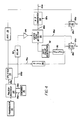
- Computer 70 then begins its data analysis in accordance with a program illustrated in the flow chart of FIGURE 7. Those data points having feature amplitude data exceeding a predetermined minimum threshold are identified as feature-indicating data points (FIDP), as represented by block 110.
- the computer then assemblies those FIDP data points that are continguously located to one another, i.e. touching each other, into exclusive, identifiable data point feature groups (DPFG), as represented by block 112.
- FIDP exclusive, identifiable data point feature groups
- computer 70 finds the maximum feature amplitude data for each feature group DPFG and computes its maximum normalized amplitude (MNA).
- MNA normalized amplitude
- This normalization computation involves correcting each maximum feature amplitude data for temperature variations in the couplant fluid (bubbler 34, FIGURE 1) and the feature depth at the data point of maximum feature amplitude.
- Temperature correction accounts for transducer focus and sensitivity changes due to couplant temperature variations.
- Feature depth correction utilizes calibration factors empirically determined from the ultrasonic examination of standard end plug welds containing features of known sizes and depths.
- the maximum normalized amplitude (MNA) for each identified feature is tested against a quality assurance threshold, and the end plug weld is rejected if this limit is exceeded, i.e., the feature is unacceptable large.
- the computer then separately counts the number of feature-indicating data points FIDP included in each feature (block 118). In FIGURE 6, this count could include the five data points of probings 101-105. From this count and knowing the data point spacing, the diameter X of each of the separate features in each scan line is computed. This diameter is then squared (X2) in each case to provide a measure of the cross sectional area of each feature included in each of the multiple transverse slices of the end plug weld respectively associated with the plural scan lines. Since pores are spherical in shape, squaring their diameters provides a rather accurate indication of their cross sectonal area included in each transverse slice.
- the thickness data for each data point is normalized using an empirically developed calibration factor and checked to find the minimum weld thickness (block 120).
- Data point thickness data which is unavailable due to the presence of features are assigned thickness data comparable to that of the data points just beyond the features.
- the end plug weld is rejected if the minimum weld thickness is less than a quality assurance established minimum limit (block 122).
- the normalized thickness data for the data points of each scan line are added together to produce a total which is proportional to the gross cross sectional area of the included transverse slice.
- the computed gross cross sectional area of each slice is then reduced by the computed feature cross sectional X2 of those features included in the respective slices (block 118) to derive a net weld cross sectional area (A) for each slice (scan line), as represented by block 126. If the minimum net cross sectional area of any slice is less than a predetermined threshold limit, the weld is rejected (block 128).
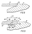
- FIGURE 8 illustrates in cross section the mated relationship of tube 16 and end plug 14 preparatory to welding. The original seam between these parts is indicated at 12b.
- FIGURE 9 illustrates in cross section an acceptable degree of weld penetration in that weld nugget 132 is seen to penetrate the tube open end well inwardly from seam 12b. Since end plug weld 12 is always precisely positioned in the inspection station 10 by line centering stop 26 (FIGURE 1) the position of seam 12b in the ultrasonic scanning pattern is known. Scanning begins over the unweld portion of the tube inwardly from nugget 132, as indicated at 134.
- Block 148 in the flow chart of FIGURE 7 indicates that the thickness data is also analyzed for possible welding process excursions.
- the volume of weld nugget 132 is calculated, and the uniformity of nugget cross sectional area in both transverse and axial planes is examined.
- the uniformities of the nugget edges 132a and 132b around their circumferences are also examined. Information developed from these examinations is utilized to monitor weld geometric characteristics and to alert personnel that welding proccess parameters may require adjustments should these characteristics show a trend away from acceptable standards. Alternatively, this information may be utilized to automatically effect feedback control of the welding process parameters.
- the data analysis may, particularly in the case of rejected welds, be programmed to display the weld examination data on color monitor 70b in the form of a graph with the axially spaced scan lines plotted along one axis and the circumferentially spaced data points of each scan line plotted along the other axis. Thickness data are indicated by variations in color. Included features are displayed as blanked pixels. A hard copy of this graph is generated by printer-plotter 70a. The computer also has all the data necessary to generate graphs for display and printing of the tube and weld thickness for any selected radial or axial slice through the weld.
Landscapes
- Physics & Mathematics (AREA)
- General Physics & Mathematics (AREA)
- Pathology (AREA)
- Life Sciences & Earth Sciences (AREA)
- Chemical & Material Sciences (AREA)
- Analytical Chemistry (AREA)
- Biochemistry (AREA)
- General Health & Medical Sciences (AREA)
- Immunology (AREA)
- Health & Medical Sciences (AREA)
- Engineering & Computer Science (AREA)
- Acoustics & Sound (AREA)
- Signal Processing (AREA)
- Plasma & Fusion (AREA)
- General Engineering & Computer Science (AREA)
- High Energy & Nuclear Physics (AREA)
- Investigating Or Analyzing Materials By The Use Of Ultrasonic Waves (AREA)
- Monitoring And Testing Of Nuclear Reactors (AREA)
Applications Claiming Priority (2)
| Application Number | Priority Date | Filing Date | Title |
|---|---|---|---|
| US250187 | 1988-09-28 | ||
| US07/250,187 US5108693A (en) | 1988-09-28 | 1988-09-28 | Non-destructive dimensional and flaw inspection of thin wall tube weldments |
Publications (3)
| Publication Number | Publication Date |
|---|---|
| EP0361890A2 true EP0361890A2 (de) | 1990-04-04 |
| EP0361890A3 EP0361890A3 (en) | 1990-08-29 |
| EP0361890B1 EP0361890B1 (de) | 1994-12-07 |
Family
ID=22946658
Family Applications (1)
| Application Number | Title | Priority Date | Filing Date |
|---|---|---|---|
| EP89309831A Expired - Lifetime EP0361890B1 (de) | 1988-09-28 | 1989-09-27 | Zerstörungsfrei Dimensions- und Fehlerkontrolle von Schweissungen an dünnwandigen Rohren |
Country Status (6)
| Country | Link |
|---|---|
| US (1) | US5108693A (de) |
| EP (1) | EP0361890B1 (de) |
| JP (1) | JPH0664020B2 (de) |
| CA (1) | CA1320759C (de) |
| DE (1) | DE68919789T2 (de) |
| ES (1) | ES2064454T3 (de) |
Cited By (1)
| Publication number | Priority date | Publication date | Assignee | Title |
|---|---|---|---|---|
| WO1992010746A1 (de) * | 1990-12-15 | 1992-06-25 | Kernforschungszentrum Karlsruhe Gmbh | Verfahren zur laufzeitmessung von ultraschall bei der impuls-reflexionsmethode |
Families Citing this family (17)
| Publication number | Priority date | Publication date | Assignee | Title |
|---|---|---|---|---|
| JPH0466896A (ja) * | 1990-07-09 | 1992-03-03 | Japan Nuclear Fuel Co Ltd<Jnf> | 原子燃料棒溶接部超音波検査装置 |
| US5533401A (en) * | 1994-05-12 | 1996-07-09 | General Electric Company | Multizone ultrasonic inspection method and apparatus |
| US6125705A (en) * | 1998-04-23 | 2000-10-03 | Bechtel Bwxt Idaho, Llc | Apparatus for the concurrent ultrasonic inspection of partially completed welds |
| SE516096C2 (sv) * | 1999-08-11 | 2001-11-19 | Westinghouse Atom Ab | Förfarande och anordning för inspektion av och mätning vid ett föremål |
| FR2805075B1 (fr) * | 2000-02-15 | 2002-05-10 | Franco Belge Combustibles | Procede de controle d'une operation de fermeture etanche par soudage de l'extremite d'un canal de remplissage traversant le bouchon superieur d'un crayon de combustible nucleaire |
| DE10222600A1 (de) * | 2002-05-17 | 2003-12-04 | Agfa Ndt Gmbh | Verfahren zum Festlegen der Grenzwerte von Blenden bei der Ultraschallprüfung von Punktschweissverbindungen |
| US7104131B2 (en) * | 2004-03-17 | 2006-09-12 | Battelle Energy Alliance, Llc | Ultrasonic pulser-receiver |
| US7512207B2 (en) * | 2005-04-12 | 2009-03-31 | General Electric Company | Apparatus for delivering a tool into a submerged bore |
| RU2395802C1 (ru) * | 2009-04-21 | 2010-07-27 | Открытое акционерное общество "Государственный ракетный центр им. академика В.П. Макеева" | Способ ультразвукового контроля стыковых сварных швов |
| RU2557679C1 (ru) * | 2014-01-30 | 2015-07-27 | Акционерное общество "Государственный ракетный центр имени академика В.П. Макеева" (АО "ГРЦ Макеева") | Способ автоматизированного ультразвукового контроля плоских изделий |
| JP6586280B2 (ja) * | 2015-03-26 | 2019-10-02 | 三菱日立パワーシステムズ株式会社 | 超音波探傷子、超音波探傷装置及び超音波探傷方法 |
| JP6618728B2 (ja) * | 2015-07-09 | 2019-12-11 | Ntn株式会社 | 等速自在継手の外側継手部材の製造方法および溶接部の超音波探傷検査方法 |
| JP6685683B2 (ja) * | 2015-09-24 | 2020-04-22 | Ntn株式会社 | 等速自在継手の外側継手部材の製造方法および溶接部の超音波探傷検査方法 |
| GB2581181B8 (en) * | 2019-02-06 | 2021-08-11 | Darkvision Tech Inc | Acoustic surface imaging using time of flight |
| JP2022526837A (ja) | 2019-04-17 | 2022-05-26 | ディーエムシー グローバル インコーポレイテッド | 多層構造の物品における強固な結合と弱い結合の間の結合境界を特定する方法及びシステム |
| DK3815884T3 (da) * | 2019-10-30 | 2024-11-11 | Fischer G Rohrleitungssysteme Ag | Fremgangsmåde til kontrol af en svejsning |
| KR102355438B1 (ko) * | 2019-11-28 | 2022-01-26 | 주식회사 씨자인 | 초음파 센서를 이용한 사물 인식 시스템 및 그 인식 방법 |
Family Cites Families (15)
| Publication number | Priority date | Publication date | Assignee | Title |
|---|---|---|---|---|
| US3169393A (en) * | 1961-04-03 | 1965-02-16 | Automation Ind Inc | Means and techniques for inspecting metal |
| NL302332A (de) * | 1963-01-02 | |||
| US4065960A (en) * | 1976-12-13 | 1978-01-03 | Krautkramer Gmbh | Method and apparatus for monitoring the operation of ultrasonic testing of tubes and bars |
| US4098130A (en) * | 1977-03-11 | 1978-07-04 | General Electric Company | Energy reflection flaw detection system |
| FR2428253A1 (fr) * | 1978-06-05 | 1980-01-04 | Commissariat Energie Atomique | Procede de controle par ultrasons de la soudure entre un tube et un bouchon d'obturation du tube et bouchon adapte a la mise en oeuvre dudit procede |
| US4213345A (en) * | 1978-07-25 | 1980-07-22 | W. C. Lamb | Pipe inspection system and method |
| US4217782A (en) * | 1978-07-25 | 1980-08-19 | W. C. Lamb | Ultrasonic inspection device and method of inspection |
| US4428237A (en) * | 1980-11-13 | 1984-01-31 | Electric Power Research Institute, Inc. | System and method for measuring ultrasonic return signals |
| US4393711A (en) * | 1980-11-13 | 1983-07-19 | Electric Power Research Institute, Inc. | Apparatus and method for ultrasonic detection of flaws in power plant piping systems |
| US4424235A (en) * | 1981-09-14 | 1984-01-03 | Hoffmann-La Roche Inc. | Hydrodynamically balanced controlled release compositions containing L-dopa and a decarboxylase inhibitor |
| US4541064A (en) * | 1982-08-11 | 1985-09-10 | Livingston Waylon A | Process for ultrasonic testing of tubular goods |
| US4554128A (en) * | 1983-03-01 | 1985-11-19 | Westinghouse Electric Corp. | Nuclear fuel rod end plug weld inspection |
| US4660419A (en) * | 1983-10-03 | 1987-04-28 | Trw Inc. | Reference standard for calibration of ultrasonic arrays |
| FR2562669B1 (fr) * | 1984-04-06 | 1986-08-22 | Vallourec | Procede et installation de detection selective de defauts dans une piece a controler |
| US4857260A (en) * | 1988-09-28 | 1989-08-15 | General Electric Company | Apparatus for assembling and welding end plugs to nuclear fuel cladding tubes and inspecting the end plug welds on an automated basis |
-
1988
- 1988-09-28 US US07/250,187 patent/US5108693A/en not_active Expired - Lifetime
-
1989
- 1989-09-20 JP JP1242407A patent/JPH0664020B2/ja not_active Expired - Fee Related
- 1989-09-27 DE DE68919789T patent/DE68919789T2/de not_active Expired - Lifetime
- 1989-09-27 ES ES89309831T patent/ES2064454T3/es not_active Expired - Lifetime
- 1989-09-27 EP EP89309831A patent/EP0361890B1/de not_active Expired - Lifetime
- 1989-09-28 CA CA000614085A patent/CA1320759C/en not_active Expired - Fee Related
Cited By (2)
| Publication number | Priority date | Publication date | Assignee | Title |
|---|---|---|---|---|
| WO1992010746A1 (de) * | 1990-12-15 | 1992-06-25 | Kernforschungszentrum Karlsruhe Gmbh | Verfahren zur laufzeitmessung von ultraschall bei der impuls-reflexionsmethode |
| US5497661A (en) * | 1990-12-15 | 1996-03-12 | Kernforschungszentrum Karlsruhe Gmbh | Method of measuring the delay of ultrasound in the pulse reflection method |
Also Published As
| Publication number | Publication date |
|---|---|
| DE68919789D1 (de) | 1995-01-19 |
| EP0361890A3 (en) | 1990-08-29 |
| US5108693A (en) | 1992-04-28 |
| DE68919789T2 (de) | 1995-07-27 |
| ES2064454T3 (es) | 1995-02-01 |
| JPH02120659A (ja) | 1990-05-08 |
| CA1320759C (en) | 1993-07-27 |
| EP0361890B1 (de) | 1994-12-07 |
| JPH0664020B2 (ja) | 1994-08-22 |
Similar Documents
| Publication | Publication Date | Title |
|---|---|---|
| EP0361890B1 (de) | Zerstörungsfrei Dimensions- und Fehlerkontrolle von Schweissungen an dünnwandigen Rohren | |
| US8265886B2 (en) | Non-destructive testing, in particular for pipes during manufacture or in the finished state | |
| US5063780A (en) | Ultrasonic dimensional and flaw inspection of thin-walled tubular elements | |
| US5063779A (en) | Non-destructive dimensional and flaw inspection of thin wall tube weldments | |
| CA1270940A (en) | Method for classification of point and elongated single defects in workpieces by means of ultrasonics | |
| CN108414623B (zh) | 一种基于超声波扫查成像的电阻点焊质量评价方法 | |
| US4680470A (en) | Method and apparatus for crack detection and characterization | |
| EP4109089B1 (de) | System und verfahren zur puls-echo detektion unterhalb der oberfläche | |
| CN117347492A (zh) | 一种高铬合金钢管道焊缝质量的检测方法 | |
| Uzun et al. | Review of Phased Array Ultrasonic Testing of Weld Joints | |
| CN112326798B (zh) | 起重机t焊缝区域缺陷的超声波检测方法 | |
| DeNale et al. | A comparison of ultrasonics and radiography for weld inspection | |
| JP3916603B2 (ja) | 超音波斜角探傷方法とその装置 | |
| CN115856081B (zh) | 适用于金属包壳的检测装置及检测方法 | |
| Johnson et al. | Weld energy reduction by using concurrent non-destructive evaluation | |
| Murugaiyan | Time of flight diffraction (TOFD), an advanced non-destructive testing technique for inspection of welds for heavy walled pressure vessels | |
| Carpentier et al. | Manual ultrasonic inspection of thin metal welds | |
| Bu et al. | Ultrasonic Phased Array Detection of Crack-Like Defects in Welds Based on Multi-Mode Total Focusing Method | |
| CA3077465C (en) | Method for checking for consistency and quality compliance in an ultrasonic scanning data file | |
| JP2770634B2 (ja) | ジャケット付きタンクの肉厚変化測定方法 | |
| Hillberg et al. | Jules Horowitz Reactor Irradiation Devices: Inspection Methods proposal | |
| CA3077993C (en) | Method for prioritizing data processing of a plurality of ultrasonic scan data files | |
| Sikorski et al. | Fast UT: A New Ultrasonic Inspection Technique | |
| NL2012363C2 (en) | Ultrasonic phased array approach. | |
| JPS6410777B2 (de) |
Legal Events
| Date | Code | Title | Description |
|---|---|---|---|
| PUAI | Public reference made under article 153(3) epc to a published international application that has entered the european phase |
Free format text: ORIGINAL CODE: 0009012 |
|
| AK | Designated contracting states |
Kind code of ref document: A2 Designated state(s): DE ES SE |
|
| PUAL | Search report despatched |
Free format text: ORIGINAL CODE: 0009013 |
|
| AK | Designated contracting states |
Kind code of ref document: A3 Designated state(s): DE ES SE |
|
| 17P | Request for examination filed |
Effective date: 19901210 |
|
| 17Q | First examination report despatched |
Effective date: 19930506 |
|
| GRAA | (expected) grant |
Free format text: ORIGINAL CODE: 0009210 |
|
| AK | Designated contracting states |
Kind code of ref document: B1 Designated state(s): DE ES SE |
|
| REF | Corresponds to: |
Ref document number: 68919789 Country of ref document: DE Date of ref document: 19950119 |
|
| EAL | Se: european patent in force in sweden |
Ref document number: 89309831.9 |
|
| REG | Reference to a national code |
Ref country code: ES Ref legal event code: FG2A Ref document number: 2064454 Country of ref document: ES Kind code of ref document: T3 |
|
| PLBE | No opposition filed within time limit |
Free format text: ORIGINAL CODE: 0009261 |
|
| STAA | Information on the status of an ep patent application or granted ep patent |
Free format text: STATUS: NO OPPOSITION FILED WITHIN TIME LIMIT |
|
| 26N | No opposition filed | ||
| PGFP | Annual fee paid to national office [announced via postgrant information from national office to epo] |
Ref country code: SE Payment date: 20020903 Year of fee payment: 14 |
|
| PGFP | Annual fee paid to national office [announced via postgrant information from national office to epo] |
Ref country code: ES Payment date: 20021009 Year of fee payment: 14 |
|
| PG25 | Lapsed in a contracting state [announced via postgrant information from national office to epo] |
Ref country code: SE Free format text: LAPSE BECAUSE OF NON-PAYMENT OF DUE FEES Effective date: 20030928 |
|
| PG25 | Lapsed in a contracting state [announced via postgrant information from national office to epo] |
Ref country code: ES Free format text: LAPSE BECAUSE OF NON-PAYMENT OF DUE FEES Effective date: 20030929 |
|
| EUG | Se: european patent has lapsed | ||
| REG | Reference to a national code |
Ref country code: ES Ref legal event code: FD2A Effective date: 20030929 |
|
| PGFP | Annual fee paid to national office [announced via postgrant information from national office to epo] |
Ref country code: DE Payment date: 20081031 Year of fee payment: 20 |