EP0361918A2 - Ecran de projection translucent - Google Patents
Ecran de projection translucent Download PDFInfo
- Publication number
- EP0361918A2 EP0361918A2 EP89309881A EP89309881A EP0361918A2 EP 0361918 A2 EP0361918 A2 EP 0361918A2 EP 89309881 A EP89309881 A EP 89309881A EP 89309881 A EP89309881 A EP 89309881A EP 0361918 A2 EP0361918 A2 EP 0361918A2
- Authority
- EP
- European Patent Office
- Prior art keywords
- screen
- lenses
- light
- projectors
- ridge
- Prior art date
- Legal status (The legal status is an assumption and is not a legal conclusion. Google has not performed a legal analysis and makes no representation as to the accuracy of the status listed.)
- Granted
Links
- 239000004922 lacquer Substances 0.000 claims abstract description 10
- VTYYLEPIZMXCLO-UHFFFAOYSA-L Calcium carbonate Chemical compound [Ca+2].[O-]C([O-])=O VTYYLEPIZMXCLO-UHFFFAOYSA-L 0.000 claims description 10
- 230000001788 irregular Effects 0.000 claims description 6
- 229910000019 calcium carbonate Inorganic materials 0.000 claims description 5
- 235000010216 calcium carbonate Nutrition 0.000 claims description 5
- 239000000463 material Substances 0.000 claims description 4
- 239000001023 inorganic pigment Substances 0.000 claims description 2
- 239000012860 organic pigment Substances 0.000 claims description 2
- 230000003287 optical effect Effects 0.000 description 14
- PNEYBMLMFCGWSK-UHFFFAOYSA-N Alumina Chemical compound [O-2].[O-2].[O-2].[Al+3].[Al+3] PNEYBMLMFCGWSK-UHFFFAOYSA-N 0.000 description 6
- 238000000034 method Methods 0.000 description 5
- VYPSYNLAJGMNEJ-UHFFFAOYSA-N Silicium dioxide Chemical compound O=[Si]=O VYPSYNLAJGMNEJ-UHFFFAOYSA-N 0.000 description 4
- 239000003086 colorant Substances 0.000 description 3
- 238000009792 diffusion process Methods 0.000 description 3
- 230000004048 modification Effects 0.000 description 3
- 238000012986 modification Methods 0.000 description 3
- 239000004925 Acrylic resin Substances 0.000 description 2
- 229920000178 Acrylic resin Polymers 0.000 description 2
- TZCXTZWJZNENPQ-UHFFFAOYSA-L barium sulfate Chemical compound [Ba+2].[O-]S([O-])(=O)=O TZCXTZWJZNENPQ-UHFFFAOYSA-L 0.000 description 2
- 230000008859 change Effects 0.000 description 2
- 239000011248 coating agent Substances 0.000 description 2
- 238000000576 coating method Methods 0.000 description 2
- 229910052681 coesite Inorganic materials 0.000 description 2
- 229910052906 cristobalite Inorganic materials 0.000 description 2
- 229910003460 diamond Inorganic materials 0.000 description 2
- 239000010432 diamond Substances 0.000 description 2
- 239000012530 fluid Substances 0.000 description 2
- 230000008569 process Effects 0.000 description 2
- 239000000377 silicon dioxide Substances 0.000 description 2
- 235000012239 silicon dioxide Nutrition 0.000 description 2
- 229910052682 stishovite Inorganic materials 0.000 description 2
- 239000000126 substance Substances 0.000 description 2
- 238000004381 surface treatment Methods 0.000 description 2
- 229910052905 tridymite Inorganic materials 0.000 description 2
- NIXOWILDQLNWCW-UHFFFAOYSA-N acrylic acid group Chemical group C(C=C)(=O)O NIXOWILDQLNWCW-UHFFFAOYSA-N 0.000 description 1
- 230000001154 acute effect Effects 0.000 description 1
- 230000008901 benefit Effects 0.000 description 1
- 230000000694 effects Effects 0.000 description 1
- 239000011521 glass Substances 0.000 description 1
- 230000006872 improvement Effects 0.000 description 1
- 239000001095 magnesium carbonate Substances 0.000 description 1
- 229910000021 magnesium carbonate Inorganic materials 0.000 description 1
- 235000014380 magnesium carbonate Nutrition 0.000 description 1
- ZLNQQNXFFQJAID-UHFFFAOYSA-L magnesium carbonate Chemical compound [Mg+2].[O-]C([O-])=O ZLNQQNXFFQJAID-UHFFFAOYSA-L 0.000 description 1
- 238000004519 manufacturing process Methods 0.000 description 1
- 239000000203 mixture Substances 0.000 description 1
- 229920003229 poly(methyl methacrylate) Polymers 0.000 description 1
- 239000004926 polymethyl methacrylate Substances 0.000 description 1
- 239000013589 supplement Substances 0.000 description 1
- 230000000007 visual effect Effects 0.000 description 1
Images




Classifications
-
- G—PHYSICS
- G03—PHOTOGRAPHY; CINEMATOGRAPHY; ANALOGOUS TECHNIQUES USING WAVES OTHER THAN OPTICAL WAVES; ELECTROGRAPHY; HOLOGRAPHY
- G03B—APPARATUS OR ARRANGEMENTS FOR TAKING PHOTOGRAPHS OR FOR PROJECTING OR VIEWING THEM; APPARATUS OR ARRANGEMENTS EMPLOYING ANALOGOUS TECHNIQUES USING WAVES OTHER THAN OPTICAL WAVES; ACCESSORIES THEREFOR
- G03B21/00—Projectors or projection-type viewers; Accessories therefor
- G03B21/54—Accessories
- G03B21/56—Projection screens
-
- G—PHYSICS
- G03—PHOTOGRAPHY; CINEMATOGRAPHY; ANALOGOUS TECHNIQUES USING WAVES OTHER THAN OPTICAL WAVES; ELECTROGRAPHY; HOLOGRAPHY
- G03B—APPARATUS OR ARRANGEMENTS FOR TAKING PHOTOGRAPHS OR FOR PROJECTING OR VIEWING THEM; APPARATUS OR ARRANGEMENTS EMPLOYING ANALOGOUS TECHNIQUES USING WAVES OTHER THAN OPTICAL WAVES; ACCESSORIES THEREFOR
- G03B21/00—Projectors or projection-type viewers; Accessories therefor
- G03B21/54—Accessories
- G03B21/56—Projection screens
- G03B21/60—Projection screens characterised by the nature of the surface
- G03B21/62—Translucent screens
- G03B21/625—Lenticular translucent screens
Definitions
- the present invention relates to a transparent rear-projection screen of the kind which on its rear side facing projectors is provided with a set of lenses for paralleling the light coming from the projectors and which on its front side is provided with horizontally spaced apart lenses in the form of upright ridges of triangular cross section and convex lenses between the ridge-shaped lenses.
- Rear-projection screens have to a great extent been used for video-projection devices, micro film readers, data machines and flight simulators. Screens of this kind are known from U.S. Patent No. 4,509,822 issued April 9, 1985.
- the three projectors are usually positioned next to each other horizontally, and enlarged pictures produced by the projectors are projected towards the transparent screen. Because the three projectors are placed next to each other, their optical axes form angles with each other. Normally the optical axes form angles with each other from 7° to 12° depending on the size of the picture tubes and the distance from the picture tubes to the transparent screen.
- the lenses on the front side of the rear-projection have been designed so that they are total refracting, that is, the light from the projectors - after having been paralleled, is directed to the flanks of the ridge-shaped lenses in the direction perpendicular to the major plane of the screen and is then refracted out through the top and flanks of the ridge-shaped lenses.
- the brightness characteristic of the green light as viewed towards the front surface of the screen is that there are two maximum values of brightness in regions offset symmetrically in two opposite directions with respect to an axis of zero-degree angle of observation towards the front surface of the screen. For each of the red and blue colour lights from the picture tubes, there are also two maximum values of brightness.
- the three colour picture tubes have their optical axes forming angles with each other, so that the maximum values of brightness of the three colours appear in mutually shifted fashion due to the difference in the angle of incidence of the lights from the picture tubes. This means that when the screen is observed from the front side at various angles to the screen, the brightness of each colour changes so that the colours shadow is produced.
- the object of the present invention is to remove the "colour shadow" problem for an observer watching the picture within approx. ⁇ 30° horizontal range in comparison to normal to the screen, i.e., within the horizontal range where the convex lenses operate.
- the above object is attained by a transparent rear-projection screen of the above stated kind in which each of the ridge-shaped upright lenses has on its flanks light diffusing means.
- the light diffusing means may be irregularities of the surfaces of the flanks, matted surfaces of the flanks, or a half-refracting coating on the flanks.
- Fig. 1 there are illustrated three projectors 1, 2 and 3 which project TV-pictures towards the rear side of a projection screen 4. These projectors emit green, red and blue light, respectively.
- the three projectors are placed next to each other horizontally, so that the middle projector 2, most often the green projector, has its optical axis perpendicular to the screen 4.
- the screen 4 consists of Fresnel means 4a for paralleling light from the projectors 1, 2 and 3 and lens means 4b for refracting the paralleled light.
- the optical axes of the projectors 1 and 3 often form an angle of 6°-l0° with the optical axis of the projector 2.
- the three projectors 1, 2 and 3, as well as projection lenses 5, 6 and 7 mounted in front of them it is possible to form - proportional to the projectors - an enlarged picture on the screen 4.
- the observer standing to the right or to the left of the screen's centre line O-O, the observer will see a red or a blue dominating picture, respectively, depending on whether the observer is closer to the red or the blue projector's optical axis.
- An observer being opposite the centre line of the screen will see the screen red dominating at the right side, if this side has the red projectors optical axis directed to the right with respect to the screen's centre line O-O.
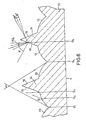
- the rear-projection screen 4 has a body 11 of e.g. an acrylic resin, having a rear side with Fresnel lenses 15 facing the projectors. These lenses 15 function to parallel the light from the projectors and direct the light to a front side of the screen 4 in a direction normal to the major plane of the screen.
- the front side of the screen is provided with a number of horizontally spaced lenses 14 in the form of upright or vertical ridges of a triangular cross section. On the both sides of each ridge-shaped lens 14, there are provided convex lenses 12 and 13.
- the Fresnel lenses 15 correspond to the means 4a shown in Fig. 1 and the lenses 12, 13 and 14 to the lens means 4b in Fig. 1.
- the light beam 17 from the projectors is converted by the Fresnel lenses 15 into a beam 17a normal to the major plane of the screen 4.
- the beam 17a is directed to the side flanks 18 and 19 of the ridge-shaped lens 14 which has an acute angle ⁇ .
- the side flanks 18 and 19 of each ridge-shaped lens 14 are coated with a half-reflecting layer 22 of lacquer of light diffusing nature.
- the lacquer has a refractive index equal to or higher than that of the material of the screen 4.
- the thickness of the layer 22 is from 2 to 3 ⁇ .
- a wax is added to the lacquer in order to achieve a desired light diffusion.
- CaCO3 is further added to the lacquer for achieving a desired light diffusing in the layer 22.
- the light beam 17a is divided into two vector bundles 20 and 21, one bundle 21 passing out through the layer 22 on one flank 19 and the other bundle 2u being produced from light reflected by the flank 19.
- the vector bundle 21 is deflected at an angle ⁇ relative to the normal to the surface of the flank 19 and normally at an angle ⁇ /4 relative to the surface of the flank 19.
- the angle ⁇ must be more than 30°, but less than 43°, preferably 37°, entirely depending on the applied lacquer's index of refraction and its dulling medium mixed.
- the vector bundles 20 and 22 going out of the screen 4 include rays of light having mutually deflected directions, which neutralize the change of colour within an angular range of ⁇ 10° relative to the normal. This phenomenon is based on the light diffusing function of the layer 22 of lacquer, which causes mixing and intersecting of rays of light.
- Fig. 4 shows the path of rays of light from two projectors, red (R) and blue (B) respectively.
- the projectors have in Fig. 4 a mutual angle of 16° between their optical axes.
- the red and the blue rays (R, B) are mixed.
- Fig. 5 shows another embodiment of the present invention in which the flanks 18 and 19 of the lens 14 are caused to have irregular surface shape or a sinusoidal surface 22A.
- the pitch of the waves of the sinusoidal surface however should not exceed three times as much as, and should be greater than the mean value of the longest wavelength of the light. Because such an irregular or sinusoidal surface has a number of normals in different directions relative to the major plane of the flanks 18 and 19, a variety of refracted rays of light 20 and 21 having deviated directions are obtained which neutralizes the change of colours. It will be understood that in Fig. 5 the irregularities are shown exaggerated and are actually minute ones.
- the irregular surface of the flanks 18 and 19 may be a mat surface.
- the mat surface is preferably made with a tool made with an artificial diamond, which, due to its granular structure, will leave an irregular surface identical to the size of the grains on the diamond.
- the minute irregularities of the matted surface will split up or mix refracted rays of light and eliminates dominating preferential direction of the light beam of each colour.
- the surface treatments A and B will give the same result as a coating.
- the screen 4 may include a light refracting medium mixed evenly therein or in one of the sides of the screen.
- the medium is an organic or inorganic pigment which serves to eliminate the colour shadow.
- Fig. 6 a division of the path of rays of green light through the upright lenses 12, 13 and 14 is shown.
- the ray G3 will not be deflected, because the surface, where the ray leaves the acrylic screen 4, is at right angle to the normal to the surface.
- the rays G1, G2 and G4 will undergo a deflection in accordance with index of refraction for the concerned screen material. If radius of curvature of the lenses 12, 13 is increased further, these lenses will involve total reflection.
- the path of rays in the lens 14 has previously been described, and it is evident in Fig. 6 that the lenses 12, 13 and 14 will supplement each other in such a manner that the viewing angle will be approx. 150°.
- Fig. 7, 8 and 9 show practical examples of rear-projection screens according to the present invention.
- a 3 mm thick plate of PMMA with 20 g SiO2 per m2 and with a grain size of 5-35 ⁇ m was cast.
- the distance D between the tops of the lenses 14 was 0.80 mm.
- the radius R of curvature of the lenses 12 and 13 was 0.30 mm, the angle ⁇ was 38°.
- the distance d between the flanks 18 and 19, where these meet radius of curvature of the lenses 12 and 13, was 0.26 mm.
- the angle ⁇ 1 - between the radius and the tangent for the lenses 12 and 13, where these meet the lens 14 - was 90°.
- the screen was coated with a lacquer, index of refraction 1, 50, and 25 g wax as well as 15 g CaCO3 per liter lacquer was added.
- the screen showed the following parameters: Peak gain: 5.6 1/2 horizontal peak gain: 38° 1/2 vertical peak gain: 7.5°.
- Peak gain means the direct transparent light measured as normal to the surface in comparison to a known reference (MgCO3).
- the screen showed good efficiency so that the picture was made visible over a big visual angle, considerably exceeding ⁇ 75°. Further the screen showed an extreme colour unity.
- Peak gain 5.8 1/2 horizontal peak gain: 36° 1/2 vertical peak gain: 8°.
- a diffusing medium e.g. be SiO2, CaCO3, BaSO4 as well as fine powdered glass with an index of refraction 0.05-0.07 larger or smaller than the basic material, which could be an acrylic resin (Polymethyl Metacrylate) with an index of refraction of 1.49.
- the significant modifications in this design is the modification of the angle ⁇ 1 from 90° to 80°. This modification will subdue the direct transparent light, i.e. light within the measuring angular range of ⁇ 8°, so that the screen will now have a lower peak gain, but a more even distribution of light.
- Peak gain 4.2 1/2 horizontal peak gain: 36° 1/2 vertical peak gain: 8°.
Landscapes
- Physics & Mathematics (AREA)
- General Physics & Mathematics (AREA)
- Overhead Projectors And Projection Screens (AREA)
- Video Image Reproduction Devices For Color Tv Systems (AREA)
Applications Claiming Priority (2)
| Application Number | Priority Date | Filing Date | Title |
|---|---|---|---|
| DK5413/88 | 1988-09-28 | ||
| DK541388A DK160593C (da) | 1988-09-28 | 1988-09-28 | Baglysprojektionsskaerm |
Publications (3)
| Publication Number | Publication Date |
|---|---|
| EP0361918A2 true EP0361918A2 (fr) | 1990-04-04 |
| EP0361918A3 EP0361918A3 (en) | 1990-07-18 |
| EP0361918B1 EP0361918B1 (fr) | 1994-01-19 |
Family
ID=8142238
Family Applications (1)
| Application Number | Title | Priority Date | Filing Date |
|---|---|---|---|
| EP89309881A Expired - Lifetime EP0361918B1 (fr) | 1988-09-28 | 1989-09-28 | Ecran de projection translucent |
Country Status (7)
| Country | Link |
|---|---|
| US (1) | US4979800A (fr) |
| EP (1) | EP0361918B1 (fr) |
| JP (1) | JP2837192B2 (fr) |
| KR (1) | KR970009132B1 (fr) |
| CA (1) | CA1324906C (fr) |
| DE (1) | DE68912487T2 (fr) |
| DK (1) | DK160593C (fr) |
Cited By (2)
| Publication number | Priority date | Publication date | Assignee | Title |
|---|---|---|---|---|
| WO1999001794A1 (fr) * | 1997-07-04 | 1999-01-14 | Scan Vision Screen Aps | Ecran de retroprojection |
| WO2001002882A1 (fr) * | 1999-07-02 | 2001-01-11 | Thomson Licensing S.A. | Feuille de lentille lenticulaire pour ecran de projection |
Families Citing this family (2)
| Publication number | Priority date | Publication date | Assignee | Title |
|---|---|---|---|---|
| US5932342A (en) * | 1996-11-14 | 1999-08-03 | Nashua Corporation | Optical diffusers obtained by fluid phase mixing of incompatible materials |
| US6424786B1 (en) | 1996-12-02 | 2002-07-23 | Honeywell International Inc. | Illumination assembly |
Family Cites Families (7)
| Publication number | Priority date | Publication date | Assignee | Title |
|---|---|---|---|---|
| DE2411557A1 (de) * | 1974-03-11 | 1975-09-25 | Mechanische Weberei Gmbh | Lichtbildprojektionswand |
| NL8004273A (nl) * | 1979-10-10 | 1981-04-14 | Bos C | Doorzichtscherm en werkwijze ter vervaardiging daarvan. |
| US4340275A (en) * | 1980-06-09 | 1982-07-20 | General Electric Company | Rear projection screen with patterned lenticular prismatic structure |
| US4418986A (en) * | 1981-04-07 | 1983-12-06 | Mitsubishi Rayon Co., Ltd. | Rear projection screen |
| JPS58176628A (ja) * | 1982-04-09 | 1983-10-17 | Mitsubishi Rayon Co Ltd | 背面投影スクリ−ン |
| JPS59111138A (ja) * | 1982-12-15 | 1984-06-27 | Matsushita Electric Ind Co Ltd | 透過型スクリ−ン |
| DK156188C (da) * | 1983-05-10 | 1989-11-27 | Scan Screen Production A S | Transparent baglysprojektionsskaerm |
-
1988
- 1988-09-28 DK DK541388A patent/DK160593C/da not_active IP Right Cessation
-
1989
- 1989-05-16 US US07/352,329 patent/US4979800A/en not_active Expired - Lifetime
- 1989-09-27 KR KR89013883A patent/KR970009132B1/ko not_active Expired - Fee Related
- 1989-09-28 JP JP1253702A patent/JP2837192B2/ja not_active Expired - Fee Related
- 1989-09-28 DE DE89309881T patent/DE68912487T2/de not_active Expired - Fee Related
- 1989-09-28 CA CA000614015A patent/CA1324906C/fr not_active Expired - Fee Related
- 1989-09-28 EP EP89309881A patent/EP0361918B1/fr not_active Expired - Lifetime
Cited By (4)
| Publication number | Priority date | Publication date | Assignee | Title |
|---|---|---|---|---|
| WO1999001794A1 (fr) * | 1997-07-04 | 1999-01-14 | Scan Vision Screen Aps | Ecran de retroprojection |
| US6304378B1 (en) | 1997-07-04 | 2001-10-16 | Scan Vision Screen Aps | Rear projection screen assembly having a projection screen with reflecting rib lenses |
| WO2001002882A1 (fr) * | 1999-07-02 | 2001-01-11 | Thomson Licensing S.A. | Feuille de lentille lenticulaire pour ecran de projection |
| US6545813B1 (en) * | 1999-07-02 | 2003-04-08 | Thomson Licensing S.A. | Lenticular lens sheet for projection screen |
Also Published As
| Publication number | Publication date |
|---|---|
| EP0361918A3 (en) | 1990-07-18 |
| DE68912487D1 (de) | 1994-03-03 |
| CA1324906C (fr) | 1993-12-07 |
| EP0361918B1 (fr) | 1994-01-19 |
| DE68912487T2 (de) | 1994-05-11 |
| DK160593C (da) | 1991-09-09 |
| JPH02118561A (ja) | 1990-05-02 |
| JP2837192B2 (ja) | 1998-12-14 |
| KR900005222A (ko) | 1990-04-13 |
| DK541388A (da) | 1990-03-29 |
| US4979800A (en) | 1990-12-25 |
| KR970009132B1 (en) | 1997-06-05 |
| DK541388D0 (da) | 1988-09-28 |
| DK160593B (da) | 1991-03-25 |
Similar Documents
| Publication | Publication Date | Title |
|---|---|---|
| CA1285161C (fr) | Ecran de type pour projection arriere | |
| US4993806A (en) | Rear-projection screen | |
| EP0372827B1 (fr) | Ecran de projection par l'arrière | |
| US4468092A (en) | Rear projection screen | |
| CA1164702A (fr) | Refracteur optique diffuseur de lumiere | |
| CA1240866A (fr) | Ecran de projection par transparence | |
| KR940006725B1 (ko) | 배면 투사 스크린 | |
| KR100248248B1 (ko) | 광학용시트,및 그것을 사용한 투과형스크린 | |
| CA1321719C (fr) | Ecran translucide | |
| EP0511721A2 (fr) | Ecran de projection par réflection avec un réseau de lentilles pour concentrer la lumière réfléchie | |
| US4509822A (en) | Transparent rear projection screen | |
| JP2993718B2 (ja) | 背面投写スクリーン | |
| US4919515A (en) | Screen for a rear projection type television set | |
| US4550977A (en) | Rear projection screen | |
| EP0361918A2 (fr) | Ecran de projection translucent | |
| JPS63165838A (ja) | 透過型スクリ−ン | |
| JPS5969748A (ja) | 透過型投影スクリ−ン | |
| JPS63265235A (ja) | 透過型投影スクリ−ン | |
| CN1004728B (zh) | 背面投影屏幕 | |
| JPS62210440A (ja) | 透過型投影スクリ−ン用レンズシ−ト | |
| JPH01195435A (ja) | 透過型スクリーン | |
| JPH04226444A (ja) | 背面投写スクリーン装置 | |
| JPS60239719A (ja) | 背面投影スクリ−ン | |
| JPS6385726A (ja) | 透過型スクリ−ン | |
| JPS61198140A (ja) | 透過式スクリ−ン |
Legal Events
| Date | Code | Title | Description |
|---|---|---|---|
| PUAI | Public reference made under article 153(3) epc to a published international application that has entered the european phase |
Free format text: ORIGINAL CODE: 0009012 |
|
| AK | Designated contracting states |
Kind code of ref document: A2 Designated state(s): DE FR IT NL |
|
| PUAL | Search report despatched |
Free format text: ORIGINAL CODE: 0009013 |
|
| AK | Designated contracting states |
Kind code of ref document: A3 Designated state(s): DE FR IT NL |
|
| 17P | Request for examination filed |
Effective date: 19900920 |
|
| 17Q | First examination report despatched |
Effective date: 19920917 |
|
| GRAA | (expected) grant |
Free format text: ORIGINAL CODE: 0009210 |
|
| AK | Designated contracting states |
Kind code of ref document: B1 Designated state(s): DE FR IT NL |
|
| ITF | It: translation for a ep patent filed | ||
| REF | Corresponds to: |
Ref document number: 68912487 Country of ref document: DE Date of ref document: 19940303 |
|
| ET | Fr: translation filed | ||
| ITTA | It: last paid annual fee | ||
| PLBI | Opposition filed |
Free format text: ORIGINAL CODE: 0009260 |
|
| 26 | Opposition filed |
Opponent name: PHILIPS ELECTRONICS N.V. Effective date: 19941017 |
|
| NLR1 | Nl: opposition has been filed with the epo |
Opponent name: PHILIPS ELECTRONICS N.V. |
|
| PLBO | Opposition rejected |
Free format text: ORIGINAL CODE: EPIDOS REJO |
|
| APAC | Appeal dossier modified |
Free format text: ORIGINAL CODE: EPIDOS NOAPO |
|
| APAE | Appeal reference modified |
Free format text: ORIGINAL CODE: EPIDOS REFNO |
|
| APAC | Appeal dossier modified |
Free format text: ORIGINAL CODE: EPIDOS NOAPO |
|
| PLBN | Opposition rejected |
Free format text: ORIGINAL CODE: 0009273 |
|
| STAA | Information on the status of an ep patent application or granted ep patent |
Free format text: STATUS: OPPOSITION REJECTED |
|
| 27O | Opposition rejected |
Effective date: 19980309 |
|
| NLR2 | Nl: decision of opposition | ||
| APAH | Appeal reference modified |
Free format text: ORIGINAL CODE: EPIDOSCREFNO |
|
| PGFP | Annual fee paid to national office [announced via postgrant information from national office to epo] |
Ref country code: FR Payment date: 20060814 Year of fee payment: 18 |
|
| PGFP | Annual fee paid to national office [announced via postgrant information from national office to epo] |
Ref country code: NL Payment date: 20060819 Year of fee payment: 18 |
|
| PGFP | Annual fee paid to national office [announced via postgrant information from national office to epo] |
Ref country code: DE Payment date: 20060828 Year of fee payment: 18 |
|
| PGFP | Annual fee paid to national office [announced via postgrant information from national office to epo] |
Ref country code: IT Payment date: 20060930 Year of fee payment: 18 |
|
| PG25 | Lapsed in a contracting state [announced via postgrant information from national office to epo] |
Ref country code: NL Free format text: LAPSE BECAUSE OF NON-PAYMENT OF DUE FEES Effective date: 20080401 |
|
| NLV4 | Nl: lapsed or anulled due to non-payment of the annual fee |
Effective date: 20080401 |
|
| PG25 | Lapsed in a contracting state [announced via postgrant information from national office to epo] |
Ref country code: DE Free format text: LAPSE BECAUSE OF NON-PAYMENT OF DUE FEES Effective date: 20080401 |
|
| PLAB | Opposition data, opponent's data or that of the opponent's representative modified |
Free format text: ORIGINAL CODE: 0009299OPPO |
|
| REG | Reference to a national code |
Ref country code: FR Ref legal event code: ST Effective date: 20080531 |
|
| PG25 | Lapsed in a contracting state [announced via postgrant information from national office to epo] |
Ref country code: FR Free format text: LAPSE BECAUSE OF NON-PAYMENT OF DUE FEES Effective date: 20071001 |
|
| PG25 | Lapsed in a contracting state [announced via postgrant information from national office to epo] |
Ref country code: IT Free format text: LAPSE BECAUSE OF NON-PAYMENT OF DUE FEES Effective date: 20070928 |