EP0361922A1 - Support d'appui pour imprimante à impact - Google Patents
Support d'appui pour imprimante à impact Download PDFInfo
- Publication number
- EP0361922A1 EP0361922A1 EP89309892A EP89309892A EP0361922A1 EP 0361922 A1 EP0361922 A1 EP 0361922A1 EP 89309892 A EP89309892 A EP 89309892A EP 89309892 A EP89309892 A EP 89309892A EP 0361922 A1 EP0361922 A1 EP 0361922A1
- Authority
- EP
- European Patent Office
- Prior art keywords
- shaft
- platen
- force
- printer
- impact
- Prior art date
- Legal status (The legal status is an assumption and is not a legal conclusion. Google has not performed a legal analysis and makes no representation as to the accuracy of the status listed.)
- Granted
Links
- 230000033001 locomotion Effects 0.000 claims abstract description 14
- 238000007639 printing Methods 0.000 claims abstract description 14
- 230000003116 impacting effect Effects 0.000 abstract description 6
- 230000000717 retained effect Effects 0.000 abstract 1
- 230000007246 mechanism Effects 0.000 description 6
- 238000005266 casting Methods 0.000 description 3
- 230000008878 coupling Effects 0.000 description 3
- 238000010168 coupling process Methods 0.000 description 3
- 238000005859 coupling reaction Methods 0.000 description 3
- 238000006073 displacement reaction Methods 0.000 description 3
- 239000002184 metal Substances 0.000 description 3
- 230000009467 reduction Effects 0.000 description 3
- 230000008901 benefit Effects 0.000 description 2
- 238000012937 correction Methods 0.000 description 2
- 239000013078 crystal Substances 0.000 description 2
- 238000013461 design Methods 0.000 description 2
- 230000003068 static effect Effects 0.000 description 2
- 229910000831 Steel Inorganic materials 0.000 description 1
- 239000011324 bead Substances 0.000 description 1
- 230000006835 compression Effects 0.000 description 1
- 238000007906 compression Methods 0.000 description 1
- 238000010276 construction Methods 0.000 description 1
- 230000001186 cumulative effect Effects 0.000 description 1
- 230000003247 decreasing effect Effects 0.000 description 1
- 230000000694 effects Effects 0.000 description 1
- 238000005516 engineering process Methods 0.000 description 1
- 231100001261 hazardous Toxicity 0.000 description 1
- 230000036541 health Effects 0.000 description 1
- 230000006872 improvement Effects 0.000 description 1
- 230000001939 inductive effect Effects 0.000 description 1
- 230000000977 initiatory effect Effects 0.000 description 1
- 239000000463 material Substances 0.000 description 1
- 238000005259 measurement Methods 0.000 description 1
- 238000000034 method Methods 0.000 description 1
- 230000005012 migration Effects 0.000 description 1
- 238000013508 migration Methods 0.000 description 1
- 230000002035 prolonged effect Effects 0.000 description 1
- 238000009877 rendering Methods 0.000 description 1
- 238000012552 review Methods 0.000 description 1
- 230000011664 signaling Effects 0.000 description 1
- 239000010959 steel Substances 0.000 description 1
- 238000012546 transfer Methods 0.000 description 1
Images

Classifications
-
- B—PERFORMING OPERATIONS; TRANSPORTING
- B41—PRINTING; LINING MACHINES; TYPEWRITERS; STAMPS
- B41J—TYPEWRITERS; SELECTIVE PRINTING MECHANISMS, i.e. MECHANISMS PRINTING OTHERWISE THAN FROM A FORME; CORRECTION OF TYPOGRAPHICAL ERRORS
- B41J11/00—Devices or arrangements of selective printing mechanisms, e.g. ink-jet printers or thermal printers, for supporting or handling copy material in sheet or web form
- B41J11/24—Detents, brakes, or couplings for feed rollers or platens
-
- B—PERFORMING OPERATIONS; TRANSPORTING
- B41—PRINTING; LINING MACHINES; TYPEWRITERS; STAMPS
- B41J—TYPEWRITERS; SELECTIVE PRINTING MECHANISMS, i.e. MECHANISMS PRINTING OTHERWISE THAN FROM A FORME; CORRECTION OF TYPOGRAPHICAL ERRORS
- B41J11/00—Devices or arrangements of selective printing mechanisms, e.g. ink-jet printers or thermal printers, for supporting or handling copy material in sheet or web form
- B41J11/02—Platens
- B41J11/04—Roller platens
Definitions
- This invention relates to a serial impact printer and, more particularly, to a platen support arrangement capable of withstanding rapidly repeating, long duration, high impact loads without generating extraneous noise.
- the office has, for many years, been a stressful environment due, in part, to the large number of objectionable noise generators, such as typewriters, high speed impact printers, paper shredders, and other office machinery. Where several such devices are placed together in a single room, the cumulative noise pollution may even be hazardous to the health and well being of its occupants. The situation is well recognized and has been addressed by governmental bodies who have set standards for maximum acceptable noise levels in office environments. Attempts have been made by the technical community to reduce the noise pollution. Some of these methods include enclosing impact printers in sound attenuating covers, designing impact printers in which the impact noise is reduced, and designing quieter printers based on non-impact technologies such as ink jet and thermal transfer.
- Noise measurements are often referenced as dBA values.
- the "A" scale by which the sound values have been identified, represents humanly perceived levels of loudness as opposed to absolute values of sound intensity.
- dB or dBA
- impact printers generate impact noise in the range of 65 to just over 80 dBA, which is deemed to be intrusive. When reduced to the high 50s dBA, the noise is construed to be objectionable or annoying. It would be highly desirable to reduce the impact noise to a dBA value in the vicinity of 50 dBA.
- the IBM Selectric ball unit typewriters generate about 78 dBA
- the Xerox Memorywriter typewriters generate about 68 dBA.
- the typewriter of the present invention has been typically measured at slightly less than 52 dBA. This represents a dramatic improvement on the order of about 100 times less noisy than present day offices, a notable achievement toward a less stressful office environment.
- the total dwell time is typically in the vicinity of 100 microseconds.
- the mean time available between character impacts is about 30 milliseconds.
- the impact noise reduction achieved by the printing mechanism of the present typewriter is made possible by significantly stretching the impact dwell time to a substantially larger fraction of the printing cycle than is typical in conventional printers. For instance, if the dwell time were stretched from 100 microseconds to 6 to 10 milliseconds, this would represent a sixty-to one hundred-fold increase, or stretch, in pulse width relative to the conventional.
- the resonant frequency is proportionally decreased and an attendant reduction in noise output can be achieved.
- a massive increase in hammer mass is required.
- a character impacting member having a high effective mass, is driven with a first force, from a starting position to the rear of a character element and then continues forward, together with the character imprinting element, which picks up the marking (or correcting) ribbon, across a throat gap into incipient contact with the platen/paper combination.
- a second force of a magnitude sufficient to release the marking material and deform the platen, is applied as soon as the control microprocessor receives a signal that contact has been made with the platen.
- the second force having a magnitude of about 18 Kg and a duration of about 10 milliseconds, would overload conventional platen mounting arrangements which usually comprise seats formed in the sheet metal side walls, probably causing deformation of the side walls and rendering the printer useless. Furthermore, the conventional seats would not restrain the substantial rebound of the platen which would vibrate and generate noise.
- the present invention may be carried out, in one form, by providing a serial impact printer comprising a platen for supporting an image receptor, the platen including a central support shaft and a cylindrical impact absorbing sleeve secured thereto, a print element having character imprinting portions disposed thereon, a print element selector for moving said print element to position a selected character imprinting portion at a printing position, a marking ribbon positionable between the print element and the platen, and means for delivering a force to the character imprinting portion so as to drive it against the platen.
- the force delivering means has an effective mass of at least 0.23 Kg and deforms said platen for a contact period of at least 1 millisecond.
- the ends of the platen shaft are captured by a mechanism including first means for withstanding, without distortion, the impact printing force, in a first direction, and second means for retaining the ends of the shaft in contact with the first means with a force sufficient to overcome rebound movement of the ends of the shaft in a second direction substantially opposite to said first direction.
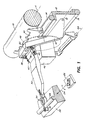
- FIG. 1 Salient features of the quiet impact printer, in which the present invention is incorporated, are shown in Figure 1. These include a platen 10 suitably mounted on a frame (not shown) for rotation about its axis 11 to advance and retract a record carrier, comprising a single sheet or a multi-part form, on which characters may be imprinted.
- a carriage support beam 12 integral with a body casting (not shown), fitted with rod stock rails 14, spans the printer from side-to-side beneath and parallel to the platen for rigidly and smoothly supporting a carriage for traversing movement parallel to the axis of the platen.
- a horseshoe-shaped interposer 16 Secured upon the carriage, for traversing movement therewith, is a horseshoe-shaped interposer 16 mounted for arcuate movement about pivot axis 18 and carrying a print tip 20 at its apex.
- a rockable bail bar 22 extends substantially parallel to the axis of platen 10 and is constrained to limited angular movement toward and away from the platen about its axis of rotation 24.
- Prime mover 26 in the form of a reciprocating voice coil motor, a rotary motor, or any other suitable driver, is connected to the bail bar for imparting the rocking movement thereto.
- a bead or rail 28 on the bail bar receives one end of push rod 30, via a pair of capturing rollers 32 and 34, for moving it toward and away from the platen as the bail bar is rocked.
- the non-collapsible push rod is a generic form of this element which is collapsible in its commercial form for allowing the print tip 20 to be drawn back away from the platen in order to allow the operator easy access to a printwheel.
- a bearing surface (not shown) on the opposite end of the push rod is biased into engagement with a seat on the rear wall of the print tip 20 by means of tension springs 38 extending between pins 40 on the push rod and suitable anchors on the interposer 16.
- the drive force of the prime mover 26 is multiplied by the bail bar 22 and is translated to the print tip 20 by the push rod 30 which may pivot about its bearing surface 36, so as to enable it to follow the arcuate path of the print tip, prescribed by the pivoting interposer 16.
- the print tip delivers the approximately 18 Kg impact force, having a duration of about 10 milliseconds, to the platen at an oblique angle in the range of about 15° to 40°.
- Pivot frame 42 is also mounted upon the carriage for pivoting movement toward and away from the platen in an arcuate path about pivot axis 44.
- a printwheel drive motor 46 having a drive shaft terminating in a coupling member (not shown), is secured to the pivot frame for movement therewith. When the operator drops a printwheel 48 into the printer, it is captured between a retaining member and the coupling member and moves together with the pivot frame.
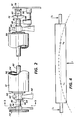
- Platen 10 extends substantially completely between printer side walls 50 and 52, although it is not supported thereon, as is done in conventional printers.
- the platen utilized in our quiet printer is more rigid than conventional platens in order that it may withstand the high impact forces delivered by the print tip 20. It comprises a central tubular steel body 54 surrounded by a resilient sleeve 56, end caps 58 secured in the body, a platen shaft 60 passing through and secured in the end caps, and bearings 62 and 64 mounted upon the shaft adjacent the end caps and held in place by retainer washers 66 and 68.
- Bearing 62 is formed with flanges 69.
- One end 70 of the platen shaft is bullet-shaped and the other end supports a drive coupling gear 72 whose hub 74 is secured to the shaft.
- the bullet-shaped platen end 70 is axially biased away from side wall 52 by button 76 supported upon side wall mounted stud 78 and biased by compression spring 80.
- a body casting which includes the carriage support beam 12, underlying the platen, has a pair of rigid upright posts 82, one on either end of the platen, each formed with a wedge-shaped saddle 84 for receiving bearings 62 and 64.
- Each of the platen bearings is urged against its respective saddle by a biasing mechanism as illustrated in Figures 3 and 3a (portions thereof are also shown in Figure 2).
- Each biasing mechanism includes a platen shaft biasing roller 86 pinned for rotation at the upper end of a generally U-shaped sheet metal pivoting plate 88, which in turn is mounted for rotation about stud 90 secured to side wall 52.
- Heavy-duty tension spring 92 is anchored to the side wall at one end and is secured to the pivoting plate at its other end, so as to urge the biasing roller against the platen shaft 60.
- a cam follower stud 94 acted upon by the camming surface 96 of pivotable release lever 98, mounted for rotation about pivot pin 100.
- Raising the actuating surface 102 frees the cam follower stud from the cam seat and allows the tension spring 92 to once again urge the pivoting plate in a counterclockwise direction about stud 90, driving the platen shaft biasing roller 86 against the platen shaft 60.
- the platen follows it and deforms in the opposite direction until contact is released and then the platen will rebound back in the direction of initial force F.
- the platen ends have a tendency to move out of the axial plane toward the front of the printer each time the platen flexes in the direction of force F.
- the bullet end 70 of shaft 60 snaps into a recess (not shown) in the apex of spring biased button 76 for positioning the platen in the correct axial position.
- the button pushes the platen shaft in the direction of arrow C it urges the left end cap 58 against the outer surface of flange of bearing 62 surface of the flange against the side wall of post 82 for eliminating noise generating axial play between the bearings and the platen shaft.
- the spring biased button 76 provides a positive load to the platen in one direction for preventing axial migration thereof, which undermines accurate correction. We have provided the flange 69 on bearing 62 to act as a stop to limit axial movement.
Landscapes
- Handling Of Sheets (AREA)
Applications Claiming Priority (2)
| Application Number | Priority Date | Filing Date | Title |
|---|---|---|---|
| US07/250,799 US4936697A (en) | 1988-09-28 | 1988-09-28 | Impact printer platen support |
| US250799 | 1988-09-28 |
Publications (2)
| Publication Number | Publication Date |
|---|---|
| EP0361922A1 true EP0361922A1 (fr) | 1990-04-04 |
| EP0361922B1 EP0361922B1 (fr) | 1993-10-27 |
Family
ID=22949200
Family Applications (1)
| Application Number | Title | Priority Date | Filing Date |
|---|---|---|---|
| EP89309892A Expired - Lifetime EP0361922B1 (fr) | 1988-09-28 | 1989-09-28 | Support d'appui pour imprimante à impact |
Country Status (4)
| Country | Link |
|---|---|
| US (1) | US4936697A (fr) |
| EP (1) | EP0361922B1 (fr) |
| JP (1) | JPH02169275A (fr) |
| DE (1) | DE68910261T2 (fr) |
Families Citing this family (4)
| Publication number | Priority date | Publication date | Assignee | Title |
|---|---|---|---|---|
| US6561641B1 (en) | 2000-02-11 | 2003-05-13 | Lexmark International, Inc. | Precision writing line control platen for high resolution ink jet printing |
| JP3432218B2 (ja) * | 2000-10-31 | 2003-08-04 | キヤノン株式会社 | プロセスカートリッジ、負荷発生部材及び電子写真画像形成装置 |
| JP2007331112A (ja) | 2006-06-12 | 2007-12-27 | Seiko Epson Corp | サーマルプリンタ |
| DE102013209703B4 (de) * | 2013-05-24 | 2017-03-30 | Greiner Tool.Tec Gmbh | Kalibriervorrichtung, Kalibrierverfahren und Verfahren zum Herstellen einer Kalibriervorrichtung |
Citations (3)
| Publication number | Priority date | Publication date | Assignee | Title |
|---|---|---|---|---|
| DE2437454B2 (de) * | 1974-08-03 | 1976-12-23 | Philips Patentverwaltung Gmbh, 2000 Hamburg | Druckwiderlager fuer druckwerke |
| US4681469A (en) * | 1985-07-02 | 1987-07-21 | Xerox Corporation | Quiet impact printer |
| EP0249419A1 (fr) * | 1986-06-10 | 1987-12-16 | Bridgestone Corporation | Cylindre de machine à écrire |
Family Cites Families (4)
| Publication number | Priority date | Publication date | Assignee | Title |
|---|---|---|---|---|
| US3154184A (en) * | 1962-06-25 | 1964-10-27 | Underwood Corp | Platen adjusting means for typewriters |
| US3342299A (en) * | 1965-12-01 | 1967-09-19 | Scm Corp | Platen ratchet assembly |
| JPS59222369A (ja) * | 1983-05-31 | 1984-12-14 | Sharp Corp | プラテン軸の簡易脱着機構 |
| US4668112A (en) * | 1985-07-02 | 1987-05-26 | Xerox Corporation | Quiet impact printer |
-
1988
- 1988-09-28 US US07/250,799 patent/US4936697A/en not_active Expired - Lifetime
-
1989
- 1989-08-25 JP JP1220111A patent/JPH02169275A/ja active Pending
- 1989-09-28 EP EP89309892A patent/EP0361922B1/fr not_active Expired - Lifetime
- 1989-09-28 DE DE68910261T patent/DE68910261T2/de not_active Expired - Fee Related
Patent Citations (3)
| Publication number | Priority date | Publication date | Assignee | Title |
|---|---|---|---|---|
| DE2437454B2 (de) * | 1974-08-03 | 1976-12-23 | Philips Patentverwaltung Gmbh, 2000 Hamburg | Druckwiderlager fuer druckwerke |
| US4681469A (en) * | 1985-07-02 | 1987-07-21 | Xerox Corporation | Quiet impact printer |
| EP0249419A1 (fr) * | 1986-06-10 | 1987-12-16 | Bridgestone Corporation | Cylindre de machine à écrire |
Also Published As
| Publication number | Publication date |
|---|---|
| JPH02169275A (ja) | 1990-06-29 |
| EP0361922B1 (fr) | 1993-10-27 |
| US4936697A (en) | 1990-06-26 |
| DE68910261D1 (de) | 1993-12-02 |
| DE68910261T2 (de) | 1994-05-19 |
Similar Documents
| Publication | Publication Date | Title |
|---|---|---|
| US3848722A (en) | Print disc assembly for a printer | |
| EP0361922B1 (fr) | Support d'appui pour imprimante à impact | |
| US4218149A (en) | Wire printer | |
| EP0207780A1 (fr) | Imprimante à impact | |
| EP0210000B1 (fr) | Imprimante à impact | |
| US4744684A (en) | Impact-type recording apparatus | |
| EP0209291A1 (fr) | Imprimante à impact | |
| EP0028539B1 (fr) | Ensemble de marteau d'impression | |
| US5199804A (en) | Quiet impact printer mechanism | |
| US4874265A (en) | Impact mechanism for impact printer | |
| US4859096A (en) | Impact mechanism for impact printer | |
| US4867584A (en) | Impact mechanism for impact printer | |
| US4893950A (en) | Apparatus and method for controlling the positioning of marking elements in a serial impact printer | |
| US4327639A (en) | Print hammer assembly with multi-location impacts | |
| EP0453115B1 (fr) | Imprimantes par impact | |
| US4324497A (en) | Print hammer assembly with amplified multi-location impacts | |
| US4134336A (en) | Half-herringbone support for restricting sideways vibration of comb hammers | |
| US3996852A (en) | Line printer | |
| EP0453142B1 (fr) | Dispositif d'avance pour ruban dans une imprimante par impact silencieux et à prix réduit | |
| US5174671A (en) | Printing mechanism with print hammer having noise dampener | |
| US5183344A (en) | Quiet impact printer mechanism | |
| JP2730277B2 (ja) | ドットインパクトプリンタの印字ヘッド | |
| JPS59156770A (ja) | インパクト型プリンタ | |
| JPH029943B2 (fr) | ||
| JPS62189163A (ja) | シリアルインパクトプリンタ用印字ホイ−ル |
Legal Events
| Date | Code | Title | Description |
|---|---|---|---|
| PUAI | Public reference made under article 153(3) epc to a published international application that has entered the european phase |
Free format text: ORIGINAL CODE: 0009012 |
|
| AK | Designated contracting states |
Kind code of ref document: A1 Designated state(s): DE FR GB IT |
|
| 17P | Request for examination filed |
Effective date: 19901004 |
|
| 17Q | First examination report despatched |
Effective date: 19920410 |
|
| GRAA | (expected) grant |
Free format text: ORIGINAL CODE: 0009210 |
|
| AK | Designated contracting states |
Kind code of ref document: B1 Designated state(s): DE FR GB IT |
|
| REF | Corresponds to: |
Ref document number: 68910261 Country of ref document: DE Date of ref document: 19931202 |
|
| ET | Fr: translation filed | ||
| ITF | It: translation for a ep patent filed | ||
| PLBE | No opposition filed within time limit |
Free format text: ORIGINAL CODE: 0009261 |
|
| STAA | Information on the status of an ep patent application or granted ep patent |
Free format text: STATUS: NO OPPOSITION FILED WITHIN TIME LIMIT |
|
| 26N | No opposition filed | ||
| PGFP | Annual fee paid to national office [announced via postgrant information from national office to epo] |
Ref country code: FR Payment date: 19970909 Year of fee payment: 9 |
|
| PGFP | Annual fee paid to national office [announced via postgrant information from national office to epo] |
Ref country code: GB Payment date: 19970919 Year of fee payment: 9 |
|
| PGFP | Annual fee paid to national office [announced via postgrant information from national office to epo] |
Ref country code: DE Payment date: 19971010 Year of fee payment: 9 |
|
| PG25 | Lapsed in a contracting state [announced via postgrant information from national office to epo] |
Ref country code: GB Free format text: LAPSE BECAUSE OF NON-PAYMENT OF DUE FEES Effective date: 19980928 |
|
| GBPC | Gb: european patent ceased through non-payment of renewal fee |
Effective date: 19980928 |
|
| PG25 | Lapsed in a contracting state [announced via postgrant information from national office to epo] |
Ref country code: FR Free format text: LAPSE BECAUSE OF NON-PAYMENT OF DUE FEES Effective date: 19990531 |
|
| PG25 | Lapsed in a contracting state [announced via postgrant information from national office to epo] |
Ref country code: DE Free format text: LAPSE BECAUSE OF NON-PAYMENT OF DUE FEES Effective date: 19990701 |
|
| REG | Reference to a national code |
Ref country code: FR Ref legal event code: ST |
|
| PG25 | Lapsed in a contracting state [announced via postgrant information from national office to epo] |
Ref country code: IT Free format text: LAPSE BECAUSE OF NON-PAYMENT OF DUE FEES;WARNING: LAPSES OF ITALIAN PATENTS WITH EFFECTIVE DATE BEFORE 2007 MAY HAVE OCCURRED AT ANY TIME BEFORE 2007. THE CORRECT EFFECTIVE DATE MAY BE DIFFERENT FROM THE ONE RECORDED. Effective date: 20050928 |