EP0361943B1 - Système de transmission automatique pour véhicules - Google Patents
Système de transmission automatique pour véhicules Download PDFInfo
- Publication number
- EP0361943B1 EP0361943B1 EP89309937A EP89309937A EP0361943B1 EP 0361943 B1 EP0361943 B1 EP 0361943B1 EP 89309937 A EP89309937 A EP 89309937A EP 89309937 A EP89309937 A EP 89309937A EP 0361943 B1 EP0361943 B1 EP 0361943B1
- Authority
- EP
- European Patent Office
- Prior art keywords
- vehicle
- gear
- gear position
- acceleration
- signal
- Prior art date
- Legal status (The legal status is an assumption and is not a legal conclusion. Google has not performed a legal analysis and makes no representation as to the accuracy of the status listed.)
- Expired - Lifetime
Links
- 230000005540 biological transmission Effects 0.000 title claims description 44
- 230000001133 acceleration Effects 0.000 claims description 33
- 238000001514 detection method Methods 0.000 claims description 3
- 239000008186 active pharmaceutical agent Substances 0.000 description 7
- 239000003795 chemical substances by application Substances 0.000 description 6
- 230000004044 response Effects 0.000 description 6
- 230000001276 controlling effect Effects 0.000 description 5
- 238000002485 combustion reaction Methods 0.000 description 3
- 230000006870 function Effects 0.000 description 2
- 230000003247 decreasing effect Effects 0.000 description 1
- 230000000994 depressogenic effect Effects 0.000 description 1
- 230000000694 effects Effects 0.000 description 1
- 239000000446 fuel Substances 0.000 description 1
- 230000007935 neutral effect Effects 0.000 description 1
- 230000001105 regulatory effect Effects 0.000 description 1
- 230000001960 triggered effect Effects 0.000 description 1
Images

Classifications
-
- F—MECHANICAL ENGINEERING; LIGHTING; HEATING; WEAPONS; BLASTING
- F16—ENGINEERING ELEMENTS AND UNITS; GENERAL MEASURES FOR PRODUCING AND MAINTAINING EFFECTIVE FUNCTIONING OF MACHINES OR INSTALLATIONS; THERMAL INSULATION IN GENERAL
- F16H—GEARING
- F16H61/00—Control functions within control units of change-speed- or reversing-gearings for conveying rotary motion ; Control of exclusively fluid gearing, friction gearing, gearings with endless flexible members or other particular types of gearing
- F16H61/16—Inhibiting or initiating shift during unfavourable conditions , e.g. preventing forward-reverse shift at high vehicle speed, preventing engine overspeed
-
- B—PERFORMING OPERATIONS; TRANSPORTING
- B60—VEHICLES IN GENERAL
- B60W—CONJOINT CONTROL OF VEHICLE SUB-UNITS OF DIFFERENT TYPE OR DIFFERENT FUNCTION; CONTROL SYSTEMS SPECIALLY ADAPTED FOR HYBRID VEHICLES; ROAD VEHICLE DRIVE CONTROL SYSTEMS FOR PURPOSES NOT RELATED TO THE CONTROL OF A PARTICULAR SUB-UNIT
- B60W10/00—Conjoint control of vehicle sub-units of different type or different function
- B60W10/02—Conjoint control of vehicle sub-units of different type or different function including control of driveline clutches
-
- B—PERFORMING OPERATIONS; TRANSPORTING
- B60—VEHICLES IN GENERAL
- B60W—CONJOINT CONTROL OF VEHICLE SUB-UNITS OF DIFFERENT TYPE OR DIFFERENT FUNCTION; CONTROL SYSTEMS SPECIALLY ADAPTED FOR HYBRID VEHICLES; ROAD VEHICLE DRIVE CONTROL SYSTEMS FOR PURPOSES NOT RELATED TO THE CONTROL OF A PARTICULAR SUB-UNIT
- B60W10/00—Conjoint control of vehicle sub-units of different type or different function
- B60W10/04—Conjoint control of vehicle sub-units of different type or different function including control of propulsion units
- B60W10/06—Conjoint control of vehicle sub-units of different type or different function including control of propulsion units including control of combustion engines
-
- B—PERFORMING OPERATIONS; TRANSPORTING
- B60—VEHICLES IN GENERAL
- B60W—CONJOINT CONTROL OF VEHICLE SUB-UNITS OF DIFFERENT TYPE OR DIFFERENT FUNCTION; CONTROL SYSTEMS SPECIALLY ADAPTED FOR HYBRID VEHICLES; ROAD VEHICLE DRIVE CONTROL SYSTEMS FOR PURPOSES NOT RELATED TO THE CONTROL OF A PARTICULAR SUB-UNIT
- B60W10/00—Conjoint control of vehicle sub-units of different type or different function
- B60W10/10—Conjoint control of vehicle sub-units of different type or different function including control of change-speed gearings
- B60W10/11—Stepped gearings
-
- B—PERFORMING OPERATIONS; TRANSPORTING
- B60—VEHICLES IN GENERAL
- B60W—CONJOINT CONTROL OF VEHICLE SUB-UNITS OF DIFFERENT TYPE OR DIFFERENT FUNCTION; CONTROL SYSTEMS SPECIALLY ADAPTED FOR HYBRID VEHICLES; ROAD VEHICLE DRIVE CONTROL SYSTEMS FOR PURPOSES NOT RELATED TO THE CONTROL OF A PARTICULAR SUB-UNIT
- B60W30/00—Purposes of road vehicle drive control systems not related to the control of a particular sub-unit, e.g. of systems using conjoint control of vehicle sub-units
- B60W30/18—Propelling the vehicle
-
- B—PERFORMING OPERATIONS; TRANSPORTING
- B60—VEHICLES IN GENERAL
- B60W—CONJOINT CONTROL OF VEHICLE SUB-UNITS OF DIFFERENT TYPE OR DIFFERENT FUNCTION; CONTROL SYSTEMS SPECIALLY ADAPTED FOR HYBRID VEHICLES; ROAD VEHICLE DRIVE CONTROL SYSTEMS FOR PURPOSES NOT RELATED TO THE CONTROL OF A PARTICULAR SUB-UNIT
- B60W2520/00—Input parameters relating to overall vehicle dynamics
- B60W2520/10—Longitudinal speed
-
- B—PERFORMING OPERATIONS; TRANSPORTING
- B60—VEHICLES IN GENERAL
- B60W—CONJOINT CONTROL OF VEHICLE SUB-UNITS OF DIFFERENT TYPE OR DIFFERENT FUNCTION; CONTROL SYSTEMS SPECIALLY ADAPTED FOR HYBRID VEHICLES; ROAD VEHICLE DRIVE CONTROL SYSTEMS FOR PURPOSES NOT RELATED TO THE CONTROL OF A PARTICULAR SUB-UNIT
- B60W2540/00—Input parameters relating to occupants
- B60W2540/10—Accelerator pedal position
-
- B—PERFORMING OPERATIONS; TRANSPORTING
- B60—VEHICLES IN GENERAL
- B60W—CONJOINT CONTROL OF VEHICLE SUB-UNITS OF DIFFERENT TYPE OR DIFFERENT FUNCTION; CONTROL SYSTEMS SPECIALLY ADAPTED FOR HYBRID VEHICLES; ROAD VEHICLE DRIVE CONTROL SYSTEMS FOR PURPOSES NOT RELATED TO THE CONTROL OF A PARTICULAR SUB-UNIT
- B60W2710/00—Output or target parameters relating to a particular sub-units
- B60W2710/10—Change speed gearings
- B60W2710/1005—Transmission ratio engaged
-
- F—MECHANICAL ENGINEERING; LIGHTING; HEATING; WEAPONS; BLASTING
- F16—ENGINEERING ELEMENTS AND UNITS; GENERAL MEASURES FOR PRODUCING AND MAINTAINING EFFECTIVE FUNCTIONING OF MACHINES OR INSTALLATIONS; THERMAL INSULATION IN GENERAL
- F16H—GEARING
- F16H61/00—Control functions within control units of change-speed- or reversing-gearings for conveying rotary motion ; Control of exclusively fluid gearing, friction gearing, gearings with endless flexible members or other particular types of gearing
- F16H61/16—Inhibiting or initiating shift during unfavourable conditions , e.g. preventing forward-reverse shift at high vehicle speed, preventing engine overspeed
- F16H2061/163—Holding the gear for delaying gear shifts under unfavorable conditions, e.g. during cornering
-
- F—MECHANICAL ENGINEERING; LIGHTING; HEATING; WEAPONS; BLASTING
- F16—ENGINEERING ELEMENTS AND UNITS; GENERAL MEASURES FOR PRODUCING AND MAINTAINING EFFECTIVE FUNCTIONING OF MACHINES OR INSTALLATIONS; THERMAL INSULATION IN GENERAL
- F16H—GEARING
- F16H59/00—Control inputs to control units of change-speed- or reversing-gearings for conveying rotary motion
- F16H59/14—Inputs being a function of torque or torque demand
- F16H59/141—Inputs being a function of torque or torque demand of rate of change of torque or torque demand
-
- F—MECHANICAL ENGINEERING; LIGHTING; HEATING; WEAPONS; BLASTING
- F16—ENGINEERING ELEMENTS AND UNITS; GENERAL MEASURES FOR PRODUCING AND MAINTAINING EFFECTIVE FUNCTIONING OF MACHINES OR INSTALLATIONS; THERMAL INSULATION IN GENERAL
- F16H—GEARING
- F16H59/00—Control inputs to control units of change-speed- or reversing-gearings for conveying rotary motion
- F16H59/48—Inputs being a function of acceleration
Definitions
- the present invention relates to an automatic transmission system for vehicles, and more particularly to a system for controlling a vehicle transmission apparatus including a friction type clutch and a gear type transmission in accordance with the operation condition of the associated vehicle to perform an automatic gear-shift operation.
- US-A-4,635,508 discloses a conventional automatic transmission in which gear shifting is controlled in accordance with generated map data.
- a rate of change detecting circuit produces an output signal corresponding to the rate of change of the vehicle speed.
- This signal is monitored by a fault detecting circuit which detects whether the level of the signal is abnormally high or low. Triggering of the fault detection circuit is indicative of a short circuit or open circuit, which could cause a sudden change to an incorrect gear. To prevent this, the gear presently engaged is held for a predetermined period of time, when the fault detection circuit is triggered. If the fault persists after the predetermined period, the transmission is shifted to a safe intermediate gear. Otherwise, the present gear is maintained.
- EP-A-0108572 discloses an automotive transmission in which gear shifting is controlled in accordance with map data generated in response to a detected vehicle speed and the degree of depression of the vehicle accelerator pedal.
- the rate of change of movement of the accelerator pedal is detected by a pedal speed sensor which generates a signal to interrupt gear shifting operation when the speed of movement is above a predetermined level.
- An object of the present invention is to provide an improved automatic transmission system for vehicles, which is able to eliminate the above-described disadvantages of the prior art.
- an automatic transmission system for vehicles in which the operations of a gear type transmission and a clutch associated with a vehicle are controlled to perform an automatic gear-shifting operation, said system comprising: a first means for producing an acceleration signal showing the amount of operation of an accelerator member; a second means for producing a vehicle speed signal showing a speed of the vehicle; a determining means responsive to at least the acceleration signal and the vehicle speed signal for determining a target gear position suitable for the operation condition of the vehicle in accordance with map data for gear-shift control; an actuating means responsive to an electric signal for manipulating the gear type transmission and the clutch; an acceleration discriminating means responsive to the vehicle speed signal for discriminating whether or not the vehicle is in an accelerating state; a manipulation discriminating means responsive to the acceleration signal for discriminating whether or not the accelerator member is moved in a direction so as to decelerate the vehicle; and a control means responsive to said determining means, said acceleration discriminating means and said manipulation discriminating means for providing said actuating means with necessary control signals for carrying out a
- FIG. 1 an embodiment of an automatic transmission system for vehicles according to the present invention is illustrated in schematic form.
- Reference numeral 1 generally designates an automatic transmission system for a vehicle (not shown) powered by an internal combustion engine 2 and the automatic transmission system 1 comprises a friction clutch 4 mounted on an engine flywheel 2a and a gear type synchromesh transmission 5.
- the friction clutch 4 is a well-known dry-type single-disc clutch having a clutch release lever 4a and a clutch release bearing 4b.
- a clutch actuator 6 having a piston rod 6a connected to the clutch release lever 4a for actuating the clutch release lever 4a.
- the clutch actuator 6 is provided with a stroke sensor 7 for detecting the position of a pressure plate 4c of the clutch 4 and a clutch signal CL indicating the position of the pressure plate 4c is produced by the stroke sensor 7.
- the clutch 4 is connected by a connecting rod 8 with the transmission 5, and the rotational output of the transmission 5 is transmitted through a propeller shaft 9 to a wheel driving mechanism 3 of the vehicle.
- the transmission 5 is actuated by a gear shifting actuator 10 associated therewith, and the gear position set in the transmission 5 is detected by a gear position sensor 11 associated with the transmission 5 to produce a gear position signal GP showing the actual gear position set in the gear transmission 5.
- the vehicle has a selector 12 with a selecting lever 12a that is manipulated by the driver to select one position from among a plurality of positions which may include, e.g., an "N" position (neutral), a "1" position (1st gear), a “2" position (2nd gear), a “D” position (automatic gear changing position), and an "R” position (reverse gear). That is, the driver manipulates the selecting lever 12a in order to select a desired control mode for the transmission 5.
- the selecting lever 12a is coupled with a selected position sensor 13 for producing a selected position signal SP showing the position of the selecting lever 12a.
- An acceleration sensor 14 is associated with an accelerator pedal 15 and produces an acceleration signal A showing the amount of operation of the accelerator pedal 15.
- Reference numeral 16 indicates a known vehicle speed sensor mounted on the propeller shaft 9 for producing a vehicle speed signal VS showing the running speed of the vehicle powered by the engine 2.
- the clutch signal CL, the gear position signal GP, the selected position signal SP, the acceleration signal A and the vehicle speed signal VS, which represent operating parameters of the vehicle, are applied to a gear-shifting control unit 17 including a central processing unit (CPU) 18, read-only memory (ROM) 19, random access memory (RAM) 20 and I/O interface 21, which are interconnected by a bus 22 to form a microcomputer.
- the input signals CL, GP, SP, A and VS are converted into digital form in the I/O interface 21 to obtain clutch data DL, gear position data DG, selected position data DS, acceleration data DA and vehicle speed data DV, respectively.
- the shift control signal SF is applied to the gear shifting actuator 10 for controlling the gear shifting actuator 10 so as to shift the gear of the transmission 5 into the determined gear position, while the clutch control signal CS is applied to a clutch control unit 23 for producing a clutch driving signal CD in response to the clutch control signal CS for commanding the engagement or disengagement of the clutch 4.
- the clutch driving signal CD drives the clutch actuator 6 so as to engage or disengage the clutch 4.
- the level of the engine control signal ES changes to high from low at the time of the start of the control operation for gear-changing in the gear-shifting control unit 17, and the level of the signal ES changes to low from high at the time of the termination of the control operation for gear-changing in the gear-shifting control unit 17.
- the engine control signal ES is supplied to an engine control unit 25 which receives the acceleration signal A, the clutch signal CL, and an engine speed signal NE output by a known speed sensor 26 associated with the internal combustion engine 2 and indicating the rotational speed of the internal combustion engine 2.
- the engine control unit 25 functions to regulate the engine speed based on the manipulation of the accelerator pedal 15. Namely, the engine control unit 25 is responsive to the acceleration signal A to produce an engine speed control signal EC, which is applied to a throttle actuator 27 for controlling the fuel supply to the engine 2. Thus, the throttle actuator 27 is actuated by the engine speed control signal EC in accordance with the amount of operation of the accelerator pedal 15 and the engine speed can be regulated in accordance with the manipulation of the accelerator pedal 15. The above-described operation is performed in the engine control unit 25 only when the level of the engine control signal ES is low.
- the engine control unit 25 When a high level engine control signal ES is applied to the engine control unit 25, the engine control unit 25 functions to maintain the engine speed at its idling speed in response to the engine speed signal NE. Accordingly the high level engine control signal ES is supplied to the engine control unit 25 when the clutch 4 is in the disengaged state during the gear shift operation, whereby it is possible to suppress excessive increase in engine speed while the clutch is disengaged for shifting the gears.
- the shift control signal SF and the clutch control signal CS can be produced as a set of control signals from the gear-shifting control unit 17 for automatically shifting the gear position of the transmission 5 to the suitable position for the operation condition of the vehicle when requested, and the transmission 5 and the clutch 4 are controlled in the usual manner by means of the gear shifting actuator 10 and the clutch actuator 6 in response to the signals SF and CS, respectively. Furthermore, it is discriminated whether or not the vehicle is now accelerating, and the control operation for shifting up the transmission 5 is inhibited during the time the vehicle is being accelerated.
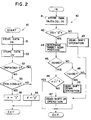
- reference numeral 30 designates a first control program which is executed at regular intervals, for example, at every 200 (ms), and reference numeral 40 designates a second control program which is repeatedly executed as appropriate.
- step 31 the acceleration data DA showing the amount of operation of the accelerator pedal 15 at that time is stored in the RAM 20.
- the operation moves to step 32 wherein the vehicle speed data DV showing the vehicle speed at that time is stored in the RAM 20.
- step 33 in order to discriminate whether or not the amount of operation of the accelerator pedal 15 is changed so as to decrease the amount of depression, in other words, whether or not the depression of the accelerator pedal 15 is reduced, acceleration data DA(n) obtained in step 31 in this program cycle is compared with the acceleration data DA(n-1) which was obtained in the preceding program cycle and is stored in the RAM 20.
- DA(n) is smaller than DA(n-1) when the accelerator pedal 15 is manipulated so as to decelerate the vehicle, so that the determination in step 33 becomes YES.
- the operation moves to step 34 wherein a flag F is cleared, and the execution of the first control program 30 is completed.
- step 33 becomes NO.
- the operation moves to step 35 wherein discrimination is made as to whether or not the vehicle speed is being increased, in other words, whether or not the vehicle is being accelerated.
- This discrimination is made by comparing vehicle speed data DV(n) obtained in step 32 executed in this program cycle and vehicle speed data DV(n-1) which was obtained in step 32 executed in the preceding program cycle, and is stored in the RAM 20.
- step 35 the determination in step 35 becomes YES and the operation moves to step 36 wherein the flag F is set.
- the execution of the first control program 30 is completed.
- step 35 the determination in step 35 becomes NO and the operation moves to step 34 wherein the flag F is cleared.
- the flag F is set only when the vehicle speed is increasing in the case where the depression of the accelerator pedal 15 is not reduced, whereby the gear-shift up operation is inhibited at gear-shift controlling according to the second control program 40.
- step 41 is executed at first, wherein the acceleration data DA, the vehicle speed data DV, the gear position data DG showing the gear shift position of the transmission 5 at that time and the selected position data DS showing the position selected by the selecting lever 12a of the selector 12 at that time are stored in the RAM 20. As described above, these data are obtained by converting the corresponding signals into digital form in the I/O 21.
- step 42 discrimination is made as to whether or not the position selected in the selector 12 is "D" position on the basis of the selected position data DS.
- step 43 an automatic gear-shift control operation is carried out in accordance with data DS in such a way that the transmission 5 is shifted to the position corresponding to the selected position represented by the selected position data DS.
- This automatic gear-shift control operation is carried out by means of the actuators 6 and 11 in accordance with the control signals SF and CS produced from the gear-shifting control unit 17 in the known usual manner.
- the execution of the second control program 40 is completed.
- step 42 becomes YES when the "D" position is selected by the selecting lever 12a, and the operation moves to step 44 wherein a suitable gear position for the operation condition of the vehicle at that time is determined as a target gear position.
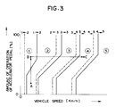
- map data for gear shift control which corresponds to the gear-shaft characteristic shown in Fig. 3, are stored in advance in ROM 19 of the gear-shifting control unit 17.
- the vehicle speed is plotted on the abscissas and the amount of operation of the accelerator pedal 15 is plotted on of ordinate.
- the solid lines indicate the conditions for shift-up operation, and the broken lines indicate the conditions for shift-down operation.
- the target gear position TG is determined in accordance with the stored map data corresponding to the gear-shift characteristic shown in Fig. 3 on the basis of the acceleration data DA and the vehicle speed data DV stored in step 41.
- step 45 the target gear position TG determined in step 44 is compared in step 45 with an actual gear position AG represented by gear position data DG stored in step 41.
- the determination is step 45 becomes YES and the operation moves to step 46 wherein a discrimination is made as to whether or not the flag F is in a set condition.
- the flag F is in its set condition of, e.g. "1"
- the execution of the second control program 40 is completed without carrying out the shift-up operation even if a higher gear position than the actual gear position AG is indicated as the target gear position TG.
- step 46 When the flag F is in a cleared condition of, e.g. "0", the determination in step 46 becomes NO and the operation moves to step 47 wherein the necessary control operation for shifting up the transmission 5 to the target gear position is carried out in accordance with the shift control signal SF and the clutch control signal CS.
- a set of control signals SF and CS for carrying out the necessary gear-shift up operation are produced from the gear-shifting control unit 17 in a known usual manner.
- the transmission 5 is automatically shifted to the target gear position determined in step 44.
- the execution of the second control program 40 is terminated.
- step 45 When the determination in step 45 becomes NO, the operation moves to step 48 wherein the target gear position TG is compared with the actual gear position AG to discriminate whether or not a shift-down operation is required.
- the determination in step 48 becomes YES when the target gear position TG shows a lower position than the actual gear position AG.
- step 48 When the determination in step 48 is YES, the operation moves to step 49 wherein the necessary control operation for shifting down to the target gear position determined in step 44 is carried out in accordance with the control signals SF and CL in the usual manner, and the execution of the second control program 40 is completed. That is, the control operation for shifting down is carried out regardless of the condition of the flag F.
- step 48 In the case where the target gear position TG is equal to the actual gear position AG, the determination in step 48 becomes NO and the execution of the second control program 40 is completed without the performance of the operation for shifting the transmission 5.
- the automatic transmission system 1 will operate as follows when the operating point A moves to the operating point B on the graph of Fig. 3 in response to the depression of the accelerator pedal 15. Just after the depression of the accelerator pedal 15, the vehicle speed increases little by little and the increase in the vehicle speed is continued until the running load of the vehicle becomes equal to the engine output of the vehicle. Thus, when the operation condition of the vehicle has reached the operating point C at which the running load becomes equal to the engine output of the vehicle, the vehicle will run at a constant speed thereafter.
- the target gear position determined in step 44 is changed from the second gear position to the third gear position, and is further changed from the third gear position to the fourth gear position during shift of the operating point from A to C.
- the determination in step 33 remains NO and that in step 35 remains YES during this period because the vehicle speed is increasing and the accelerator pedal 15 is not released, the flag F is set just after the accelerator pedal 15 is depressed and the set condition of the flag F is continued. Therefore, the control operation for shifting up is not carried out irrespective of the fact that a higher gear position than the actual gear position is determined as the target gear position.
- step 35 of the first control program 30 becomes NO to clear the flag F in step 34.
- the necessary operation is carried out for automatically shifting up the transmission 5 to the fourth gear position.
- the driver is able to estimate the time of the operation for shifting up beforehand on the basis of the change in the vehicle speed, and is able to decide the time of the shift-up only by manipulation of the acceleration pedal 15.
Landscapes
- Engineering & Computer Science (AREA)
- Mechanical Engineering (AREA)
- Chemical & Material Sciences (AREA)
- Combustion & Propulsion (AREA)
- Transportation (AREA)
- General Engineering & Computer Science (AREA)
- Automation & Control Theory (AREA)
- Control Of Transmission Device (AREA)
- Control Of Driving Devices And Active Controlling Of Vehicle (AREA)
Claims (3)
- Système de transmission automatique (1) pour véhicules dans lequel l'actionnement d'une transmission du type à étages (5) et d'un embrayage (4) associés au véhicule est commandé pour effectuer une opération de changement de vitesse automatique, ledit système comprenant :
un premier moyen (14) permettant de produire un signal d'accélération (A) indiquant le degré d'actionnement d'un élément accélérateur (15) ;
un second moyen (16) permettant de produire un signal de vitesse de véhicule (VS) indiquant une vitesse du véhicule ;
un moyen de détermination répondant au moins au signal d'accélération (A) et au signal de vitesse de véhicule (VS), permettant de déterminer une position de rapport cible, adaptée aux conditions de fonctionnement du véhicule en fonction des données de la carte de commande de changement de vitesse ;
un moyen d'actionnement (10) répondant à un signal électrique, permettant d'actionner la transmission de type à étages (5) et l'embrayage (4) ;
un moyen de discrimination d'accélération répondant au signal de vitesse de véhicule (VS), permettant de détecter si le véhicule se trouve ou non en phase d'accélération ;
un moyen de discrimination d'actionnement répondant au signal d'accélération (A), permettant de détecter si l'élément accélérateur (15) est déplacé ou non dans une direction tendant à faire décélérer le véhicule ; et
un moyen de commande (17) répondant audit moyen de détermination, audit moyen de discrimination d'accélération et audit moyen de discrimination d'actionnement, permettant de fournir auxdits moyens d'actionnement les signaux de commande nécessaires pour engager une vitesse supérieure uniquement lorsque la position de rapport cible, déterminée par ledit moyen de détermination, est supérieure à la position de rapport effective et lorsque ledit moyen de discrimination d'accélération détecte que le véhicule ne se trouve pas en phase d'accélération, dans le cas où l'élément accélérateur (15) n'est pas déplacé dans une direction tendant à faire décélérer le véhicule. - Système selon la revendication 1, caractérisé en ce que le moyen de discrimination d'accélération répond au signal de vitesse de véhicule (VS) et détecte, en fonction des variations de vitesse du véhicule avec le temps, si le véhicule se trouve ou non en phase d'accélération.
- Système selon la revendication 1 ou 2, caractérisé en ce que le moyen de commande (17) comprend un moyen de détection (11) permettant de détecter une position de rapport effective (GP) de la transmission (5), un moyen de comparaison permettant de comparer le résultat de la détection par le moyen de détection (11) avec la position de rapport cible déterminée par le moyen de détermination, et des moyens répondant au moyen de comparaison, au moyen de discrimination d'accélération et au moyen de discrimination d'actionnement, permettant de fournir au moyen d'actionnement (10) les signaux de commande nécessaires pour engager la vitesse supérieure cible uniquement lorsque le véhicule ne se trouve pas en phase d'accélération, lorsque l'élément accélérateur (15) n'est pas déplacé dans une direction tendant à faire décélérer le véhicule et lorsque la position de rapport cible est supérieure à la position de rapport effective (GP).
Applications Claiming Priority (2)
| Application Number | Priority Date | Filing Date | Title |
|---|---|---|---|
| JP244275/88 | 1988-09-30 | ||
| JP63244275A JPH0293163A (ja) | 1988-09-30 | 1988-09-30 | 車輌用自動変速装置 |
Publications (3)
| Publication Number | Publication Date |
|---|---|
| EP0361943A2 EP0361943A2 (fr) | 1990-04-04 |
| EP0361943A3 EP0361943A3 (fr) | 1991-03-20 |
| EP0361943B1 true EP0361943B1 (fr) | 1994-08-24 |
Family
ID=17116326
Family Applications (1)
| Application Number | Title | Priority Date | Filing Date |
|---|---|---|---|
| EP89309937A Expired - Lifetime EP0361943B1 (fr) | 1988-09-30 | 1989-09-29 | Système de transmission automatique pour véhicules |
Country Status (4)
| Country | Link |
|---|---|
| US (1) | US4977992A (fr) |
| EP (1) | EP0361943B1 (fr) |
| JP (1) | JPH0293163A (fr) |
| DE (1) | DE68917668T2 (fr) |
Cited By (1)
| Publication number | Priority date | Publication date | Assignee | Title |
|---|---|---|---|---|
| DE10001350B4 (de) * | 1999-01-14 | 2006-12-28 | Aisin Ai Co., Ltd., Nishio | Steuerverfahren zum Steuern eines automatisch betätigten Getriebes |
Families Citing this family (19)
| Publication number | Priority date | Publication date | Assignee | Title |
|---|---|---|---|---|
| DE69019172T2 (de) * | 1989-01-13 | 1995-10-12 | Iveco Fiat | Kraftfahrzeug-Antriebssteuerungssystem. |
| JPH02253050A (ja) * | 1989-03-27 | 1990-10-11 | Diesel Kiki Co Ltd | 車輌用自動変速装置の制御方法 |
| JPH0660681B2 (ja) * | 1989-06-26 | 1994-08-10 | マツダ株式会社 | 自動変速機の変速制御装置 |
| JPH0361726A (ja) * | 1989-07-28 | 1991-03-18 | Zexel Corp | 車輛用変速装置の制御方法 |
| JP2568923B2 (ja) * | 1989-10-16 | 1997-01-08 | 本田技研工業株式会社 | 無段変速機の制御方法 |
| US5335174A (en) * | 1990-04-04 | 1994-08-02 | Zexel Corporation | Correcting method for data used for control operation of vehicular clutch |
| KR0182775B1 (ko) * | 1990-04-18 | 1999-04-01 | 미다 가쓰시게 | 자동차의 구동력 제어장치 및 제어방법 |
| US5496227A (en) * | 1990-04-18 | 1996-03-05 | Hitachi, Ltd. | Torque control method and apparatus for internal combustion engine and motor vehicles employing the same |
| US5241476A (en) * | 1990-05-08 | 1993-08-31 | Chrysler Corporation | Acceleration prediction responsive adaptive upshift control |
| JPH0446266A (ja) * | 1990-06-14 | 1992-02-17 | Zexel Corp | 車輛用変速機の制御方法 |
| JP2823946B2 (ja) * | 1990-07-16 | 1998-11-11 | 株式会社ゼクセル | 自動変速装置 |
| US5279328A (en) * | 1993-01-19 | 1994-01-18 | Fluoroware, Inc. | Weir valve with adjustable bypass |
| GB9602731D0 (en) * | 1996-02-10 | 1996-04-10 | Ap Kongsberg Holdings Ltd | Transmission control systems |
| EP0867327B1 (fr) | 1997-03-29 | 2002-12-11 | Volkswagen Aktiengesellschaft | Système de contrôle pour boíte de vitesses automatisée avec interruption de l'entraínement |
| JP3490250B2 (ja) * | 1997-05-14 | 2004-01-26 | ジヤトコ株式会社 | 自動変速機のセレクト制御装置 |
| US6935204B2 (en) * | 2003-10-31 | 2005-08-30 | Caterpillar Inc | Automated manual transmission and shift method |
| CN100429432C (zh) * | 2005-06-21 | 2008-10-29 | 比亚迪股份有限公司 | Amt车辆的档位控制系统及进行档位控制的方法 |
| DE102012212936A1 (de) * | 2012-07-24 | 2014-01-30 | Zf Friedrichshafen Ag | Steuergerät, Getriebe, Antriebsstrang, Verfahren zum Ansteuern eines Getriebes und Programm |
| JP6738958B2 (ja) * | 2017-03-15 | 2020-08-12 | 日立オートモティブシステムズ株式会社 | 車両の変速機制御装置 |
Family Cites Families (11)
| Publication number | Priority date | Publication date | Assignee | Title |
|---|---|---|---|---|
| JPS55132451A (en) * | 1979-04-03 | 1980-10-15 | Nissan Motor Co Ltd | Speed change control device for automatic speed changer |
| JPS57146944A (en) * | 1981-03-04 | 1982-09-10 | Toyota Motor Corp | Speed change controller of automatic speed changer |
| JPS5981230A (ja) * | 1982-10-30 | 1984-05-10 | Isuzu Motors Ltd | 電子制御式トランスミツシヨンの変速制御方式 |
| JPS59151655A (ja) * | 1983-02-16 | 1984-08-30 | Mitsubishi Electric Corp | 車両用自動変速機の制御装置 |
| JPS601449A (ja) * | 1983-06-16 | 1985-01-07 | Mitsubishi Electric Corp | 車輛用自動変速機の制御装置 |
| US4591038A (en) * | 1983-06-16 | 1986-05-27 | Fujitsu Limited | Automatic clutch control system |
| JPS6011758A (ja) * | 1983-06-30 | 1985-01-22 | Isuzu Motors Ltd | 自動変速機の変速制御法 |
| JPS61192954A (ja) * | 1985-02-21 | 1986-08-27 | Diesel Kiki Co Ltd | 車輛用自動変速装置 |
| DE3621674A1 (de) * | 1985-07-05 | 1987-01-08 | Volkswagen Ag | Getriebeschalteinrichtung |
| JPS63111350A (ja) * | 1986-10-29 | 1988-05-16 | Toyota Motor Corp | 車両用自動変速装置のシフト制御方法 |
| JPS63167162A (ja) * | 1986-12-27 | 1988-07-11 | Isuzu Motors Ltd | 電子制御自動変速機の制御装置 |
-
1988
- 1988-09-30 JP JP63244275A patent/JPH0293163A/ja active Pending
-
1989
- 1989-09-26 US US07/412,682 patent/US4977992A/en not_active Expired - Fee Related
- 1989-09-29 DE DE68917668T patent/DE68917668T2/de not_active Expired - Fee Related
- 1989-09-29 EP EP89309937A patent/EP0361943B1/fr not_active Expired - Lifetime
Cited By (1)
| Publication number | Priority date | Publication date | Assignee | Title |
|---|---|---|---|---|
| DE10001350B4 (de) * | 1999-01-14 | 2006-12-28 | Aisin Ai Co., Ltd., Nishio | Steuerverfahren zum Steuern eines automatisch betätigten Getriebes |
Also Published As
| Publication number | Publication date |
|---|---|
| EP0361943A3 (fr) | 1991-03-20 |
| EP0361943A2 (fr) | 1990-04-04 |
| US4977992A (en) | 1990-12-18 |
| DE68917668D1 (de) | 1994-09-29 |
| DE68917668T2 (de) | 1994-12-15 |
| JPH0293163A (ja) | 1990-04-03 |
Similar Documents
| Publication | Publication Date | Title |
|---|---|---|
| US4977992A (en) | Automatic transmission system for vehicles | |
| US4848529A (en) | Automatic transmission system | |
| EP0696341B1 (fr) | Systeme de commande d'embrayage | |
| EP1342930B1 (fr) | Dispositif et méthode de commande d'embrayage de véhicule | |
| US5065849A (en) | Method for correcting data used for a clutch control operation | |
| US4852006A (en) | Amt off-highway downshift logic | |
| EP0352551B1 (fr) | Logique pour passer à des rapports supérieurs | |
| US5875410A (en) | Dynamic best gear selection for automated transmission system | |
| US5050714A (en) | System and method for controlling vehicle drive-off | |
| EP0273735B1 (fr) | Système de commande électronique pour transmission automatique | |
| US5024305A (en) | Method for controlling vehicle transmission systems | |
| US6066071A (en) | Automated transmission downshift control | |
| US4825993A (en) | Automatic transmission system for vehicles | |
| US4838397A (en) | Apparatus for controlling vehicle having an automatic transmission system | |
| JP2004527713A (ja) | 車両の自動変速機用シフト装置 | |
| EP0466036B1 (fr) | Ensemble de propulsion automatisé pour véhicule utilitaire | |
| EP0390396B1 (fr) | Méthode pour commander des systèmes de transmission automatiques de véhicules | |
| EP0390423B1 (fr) | Méthode pour commander un moteur à combustion interne pour véhicule avec système de transmission automatique | |
| EP1070880B1 (fr) | Commande adaptative de passages descendant des rapports d'une boíte de vitesses automatisée | |
| EP1013497B1 (fr) | Contrôle des phases de rétrogradage dans une transmission automatique | |
| US6231474B1 (en) | Automated transmission downshift control | |
| KR102244528B1 (ko) | 변속점 이동을 통한 변속 제어 방법 및 장치 | |
| KR100300299B1 (ko) | 적합한플-어웨이선택장치및방법 | |
| CN114135661A (zh) | 自动变速器强制降挡功能控制方法 | |
| GB2338277A (en) | Clutch control system. |
Legal Events
| Date | Code | Title | Description |
|---|---|---|---|
| PUAI | Public reference made under article 153(3) epc to a published international application that has entered the european phase |
Free format text: ORIGINAL CODE: 0009012 |
|
| 17P | Request for examination filed |
Effective date: 19891013 |
|
| AK | Designated contracting states |
Kind code of ref document: A2 Designated state(s): DE GB |
|
| PUAL | Search report despatched |
Free format text: ORIGINAL CODE: 0009013 |
|
| AK | Designated contracting states |
Kind code of ref document: A3 Designated state(s): DE GB |
|
| 17Q | First examination report despatched |
Effective date: 19930114 |
|
| GRAA | (expected) grant |
Free format text: ORIGINAL CODE: 0009210 |
|
| AK | Designated contracting states |
Kind code of ref document: B1 Designated state(s): DE GB |
|
| REF | Corresponds to: |
Ref document number: 68917668 Country of ref document: DE Date of ref document: 19940929 |
|
| PLBE | No opposition filed within time limit |
Free format text: ORIGINAL CODE: 0009261 |
|
| STAA | Information on the status of an ep patent application or granted ep patent |
Free format text: STATUS: NO OPPOSITION FILED WITHIN TIME LIMIT |
|
| 26N | No opposition filed | ||
| PGFP | Annual fee paid to national office [announced via postgrant information from national office to epo] |
Ref country code: GB Payment date: 19981001 Year of fee payment: 10 |
|
| PGFP | Annual fee paid to national office [announced via postgrant information from national office to epo] |
Ref country code: DE Payment date: 19981005 Year of fee payment: 10 |
|
| PG25 | Lapsed in a contracting state [announced via postgrant information from national office to epo] |
Ref country code: GB Free format text: LAPSE BECAUSE OF NON-PAYMENT OF DUE FEES Effective date: 19990929 |
|
| GBPC | Gb: european patent ceased through non-payment of renewal fee |
Effective date: 19990929 |
|
| PG25 | Lapsed in a contracting state [announced via postgrant information from national office to epo] |
Ref country code: DE Free format text: LAPSE BECAUSE OF NON-PAYMENT OF DUE FEES Effective date: 20000701 |