EP0361945A2 - Mesure de vitesse doppler - Google Patents
Mesure de vitesse doppler Download PDFInfo
- Publication number
- EP0361945A2 EP0361945A2 EP89309941A EP89309941A EP0361945A2 EP 0361945 A2 EP0361945 A2 EP 0361945A2 EP 89309941 A EP89309941 A EP 89309941A EP 89309941 A EP89309941 A EP 89309941A EP 0361945 A2 EP0361945 A2 EP 0361945A2
- Authority
- EP
- European Patent Office
- Prior art keywords
- base value
- phase signal
- detected
- phase
- doppler velocity
- Prior art date
- Legal status (The legal status is an assumption and is not a legal conclusion. Google has not performed a legal analysis and makes no representation as to the accuracy of the status listed.)
- Withdrawn
Links
Images
Classifications
-
- G—PHYSICS
- G01—MEASURING; TESTING
- G01S—RADIO DIRECTION-FINDING; RADIO NAVIGATION; DETERMINING DISTANCE OR VELOCITY BY USE OF RADIO WAVES; LOCATING OR PRESENCE-DETECTING BY USE OF THE REFLECTION OR RERADIATION OF RADIO WAVES; ANALOGOUS ARRANGEMENTS USING OTHER WAVES
- G01S15/00—Systems using the reflection or reradiation of acoustic waves, e.g. sonar systems
- G01S15/02—Systems using the reflection or reradiation of acoustic waves, e.g. sonar systems using reflection of acoustic waves
- G01S15/50—Systems of measurement, based on relative movement of the target
- G01S15/58—Velocity or trajectory determination systems; Sense-of-movement determination systems
- G01S15/582—Velocity or trajectory determination systems; Sense-of-movement determination systems using transmission of interrupted pulse-modulated waves and based upon the Doppler effect resulting from movement of targets
- G01S15/584—Velocity or trajectory determination systems; Sense-of-movement determination systems using transmission of interrupted pulse-modulated waves and based upon the Doppler effect resulting from movement of targets with measures taken for suppressing velocity ambiguities, i.e. anti-aliasing
Definitions
- the present invention relates to a method and a device for measuring Doppler velocity in which a base value is estimated on the basis of previously input phase signals and a detected phase signal is compared with the base value whereby Doppler velocity data is detected.
- aliasing A well recognised phenomenon, called “aliasing", wherein blood flow appears to have a different velocity or direction than it actually has, occurs when blood flow exceeds a maximum velocity decided with given ultrasonic wave carrier frequency and pulse repetition frequency.
- the aliasing results from the fact that Doppler frequency is larger than 1/2 of pulse frequency. Accordingly, there is desired a new approach in which the aliasing effect does not appear in the detected signals.
- the detected Doppler frequency shift, fd is that which would have been produced by a Doppler system transmitting and demodulating at the difference frequency ⁇ fo (equal to f1-f2). Since ⁇ fo can be made much smaller than f1 or f2, fd will be proportionally smaller than fd1 or fd2.
- a method for measuring Doppler velocity is characterised by estimating a base value from two phase signals detected at two different times and obtaining Doppler velocity data due to a difference between the base value and a new detected phase signal.
- a device for measuring Doppler velocity is characterised by a phase signal outputting means for successively outputting detected phase signals by successively emitting and receiving ultrasonic wave, a memory for successively memorising the phase signals from the phase signal outputting means, a base value estimating means for estimating a base value from at least two phase signals read out of the memory, and a comparing means for comparing a new phase signal output from the phase signal outputting means with the base value from the base value estimating means after the base value has been estimated in the base value estimating means, whereby Doppler velocity data is detected by the difference between the new phase signal and the base value.
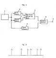
- a phase signal outputting means 1 successively outputs phase signals.
- the phase signals are obtained by emitting ultrasonic wave signals in fluid. That is, when pulses having a frequency are output from a transmitter, ultrasonic wave signals are emitted from a piezoelectric vibrator to the fluid and the echo signals of the ultrasonic wave are detected with the piezoelectric vibrator.
- the processed signals have frequencies changed by the velocity of the fluid and are called Doppler signals.
- the first phase signal output from the phase signal outputting means is memorised in a first memory 2 and the next phase signal is memorised in a second memory 3.
- a base value signal is estimated in the base value estimating means 4 on the basis of the phase signals read out of the first memory 2 and the second memory 3 and is output from the base value estimating means 4.
- the first phase signal is eliminated from the first memory 2 and the third phase signal is memorised in the first memory 2 and is latched in a latch circuit 5.
- the third phase signal latched in the latch circuit 5 is compared with the base value signal from the base value estimating means 4 in the compare circuit 6.
- the difference signal between the third phase signal and the base value signal is output from an output terminal 7 as Doppler velocity data.
- the next base value signal is estimated in the base value estimating means 4 on the basis of the second phase signal and the third phase signal.
- the fourth phase signal is memorised in the second memory 3 and is latched in the latch circuit 5, the next base value signal from the base value estimating means 4 is compared with the fourth phase signal from the latch circuit 5 and the difference signal between the next base value signal and the fourth phase signal is output from the output terminal 7 as Doppler velocity data.
- the first phase signal P1 is memorised in the first memory 2
- the second phase signal P2 is memorised in the second memory 3 and the base value I1 is estimated on the basis of the first and second phase signals.
- the first phase signal P1 is eliminated from the first memory 2
- the third phase signal P3 is memorised in the first memory 2 and is latched in the latch circuit 5, and the base value I1 and the third phase signal P3 are compared with each other in the compare circuit 6.
- the next base value I2 is estimated in the base value estimating means 4 on the basis of the second phase signal P2 and the third phase signal P3.
- the base value is estimated on the basis of the two phase signals respectively memorised in the memories 2 and 3 and the Doppler velocity signal is detected by comparing the next phase signal with the base value so that a large change of the Doppler velocity data is detectable.
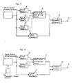
- a phase signal outputting means 1 a first memory 2, a second memory 3, a base value estimating means 4, a latch circuit 5 and a compare circuit 6.
- a third memory 8 is connected between the phase signal outputting means 1 and the base value estimating means 4.
- a base value is estimated on the basis of three phase signals memorised in the first, second and third memories 2, 3 and 8 and is compared with the next phase signal, whereby Doppler velocity data is detected.
- phase signal outputting means 1 a first memory 2, a second memory 3, a base value estimating means 4, a latch circuit 5 and a compare circuit 6.
- a frequency change circuit 9 is connected to the phase signal outputting means 1.
- the phase signals from the phase signal outputting means 1 are memorised in the first and second memories 2 and 3, and the base value is estimated on the basis of these phase signals.
- the Doppler frequency of the ultrasonic wave signal transmitted and received in the phase signal outputting means is made large by the frequency change circuit 9, the phase signal of the large Doppler frequency is latched in the latch circuit 5 and this phase signal is compared with the base value in the compare circuit 6. Accordingly, the difference signal between the signals becomes large. Thereby, in low blood velocity, the Doppler velocity data can be detected as a large phase signal.
- the distance between the phase signal P2 and the base value signal I1 is set by the integer times (one time in general) of the distance between the phase signals P1 and P2, the precision of the estimated signals is improved.
- the difference between the estimated base value and the input phase signal is clearly distinguished and large velocity data is reliably obtained, even though the present invention is simple in construction and is operated in real time.
Landscapes
- Physics & Mathematics (AREA)
- Engineering & Computer Science (AREA)
- Radar, Positioning & Navigation (AREA)
- Remote Sensing (AREA)
- Acoustics & Sound (AREA)
- Computer Networks & Wireless Communication (AREA)
- General Physics & Mathematics (AREA)
- Ultra Sonic Daignosis Equipment (AREA)
- Radar Systems Or Details Thereof (AREA)
- Measurement Of Velocity Or Position Using Acoustic Or Ultrasonic Waves (AREA)
Applications Claiming Priority (1)
| Application Number | Priority Date | Filing Date | Title |
|---|---|---|---|
| JP63248796A JPH0341385A (ja) | 1988-09-30 | 1988-09-30 | 基準推定ドプラ速度測定方法及び装置 |
Publications (2)
| Publication Number | Publication Date |
|---|---|
| EP0361945A2 true EP0361945A2 (fr) | 1990-04-04 |
| EP0361945A3 EP0361945A3 (fr) | 1991-04-24 |
Family
ID=17183525
Family Applications (1)
| Application Number | Title | Priority Date | Filing Date |
|---|---|---|---|
| EP19890309941 Withdrawn EP0361945A3 (fr) | 1988-09-30 | 1989-09-29 | Mesure de vitesse doppler |
Country Status (3)
| Country | Link |
|---|---|
| US (1) | US5216639A (fr) |
| EP (1) | EP0361945A3 (fr) |
| JP (1) | JPH0341385A (fr) |
Families Citing this family (3)
| Publication number | Priority date | Publication date | Assignee | Title |
|---|---|---|---|---|
| US5570094A (en) * | 1995-10-10 | 1996-10-29 | Armstrong; Brian S. R. | Three dimensional tracking by array doppler radar |
| US6614719B1 (en) * | 2002-04-23 | 2003-09-02 | Mattel, Inc. | Ultrasonic doppler effect speed measurement |
| US9912415B2 (en) * | 2013-11-12 | 2018-03-06 | Qualcomm Incorporated | Fast service discovery and pairing using ultrasonic communication |
Family Cites Families (11)
| Publication number | Priority date | Publication date | Assignee | Title |
|---|---|---|---|---|
| US3798590A (en) * | 1968-09-12 | 1974-03-19 | Us Navy | Signal processing apparatus including doppler dispersion correction means |
| CA1135827A (fr) * | 1978-12-04 | 1982-11-16 | Rainer Fehr | Methode de mesure de vitesses de debit en mesurant la difference de phase entre signaux doppler |
| JPS58188433A (ja) * | 1982-04-28 | 1983-11-02 | アロカ株式会社 | 超音波診断装置 |
| US4556067A (en) * | 1984-01-10 | 1985-12-03 | D. E. Hokanson, Inc. | Bandwidth indicator for Doppler blood flowmeters |
| FR2562675B1 (fr) * | 1984-04-06 | 1989-10-13 | Cgr Ultrasonic | Procede de levee d'ambiguite de la mesure par effet doppler de la vitesse d'un mobile |
| US4607642A (en) * | 1984-04-19 | 1986-08-26 | Advanced Technology Laboratories | Unaliased quadrature audio synthesizer |
| US4534357A (en) * | 1984-04-19 | 1985-08-13 | Advanced Technology Laboratories, Inc. | Multiple demodulation frequency Doppler |
| CA1246732A (fr) * | 1984-06-23 | 1988-12-13 | Aloka Co., Ltd. | Convertisseur de frequence pour signaux doppler |
| US4759375A (en) * | 1985-12-26 | 1988-07-26 | Aloka Co., Ltd. | Ultrasonic doppler diagnostic apparatus |
| JPS63179275A (ja) * | 1987-01-21 | 1988-07-23 | Aloka Co Ltd | ドプラ信号変換装置 |
| JP2553635B2 (ja) * | 1988-06-15 | 1996-11-13 | 松下電器産業株式会社 | 超音波ドップラ血流計 |
-
1988
- 1988-09-30 JP JP63248796A patent/JPH0341385A/ja active Pending
-
1989
- 1989-09-29 EP EP19890309941 patent/EP0361945A3/fr not_active Withdrawn
-
1990
- 1990-03-30 US US07/773,573 patent/US5216639A/en not_active Expired - Lifetime
Also Published As
| Publication number | Publication date |
|---|---|
| JPH0341385A (ja) | 1991-02-21 |
| US5216639A (en) | 1993-06-01 |
| EP0361945A3 (fr) | 1991-04-24 |
Similar Documents
| Publication | Publication Date | Title |
|---|---|---|
| US6278397B1 (en) | Quiet radar method and apparatus | |
| US5115242A (en) | In-furnace slag level measuring apparatus | |
| US4534357A (en) | Multiple demodulation frequency Doppler | |
| GB2280564A (en) | Noise reduction in pulse radar | |
| AU6640790A (en) | Velocity measurement system | |
| US7064704B2 (en) | Apparatus for radar | |
| EP0322017B1 (fr) | Dispositif radar utilisant différents types d'impulsions | |
| US3898653A (en) | Automotive radar sensor | |
| JPH063442A (ja) | レーダー装置及び方法 | |
| EP0063496B1 (fr) | Télémètre radar émettant des signaux codés | |
| EP0361945A2 (fr) | Mesure de vitesse doppler | |
| US3863198A (en) | Doppler sonar utilizing period measurement with thresholded receivers | |
| US6525686B2 (en) | Receiving/transmitting apparatus and radar equipment | |
| JP2007500857A (ja) | 静止状態で高度計を自己試験するためにドップラー信号をシミュレートするための方法および装置 | |
| CA1246732A (fr) | Convertisseur de frequence pour signaux doppler | |
| US3987443A (en) | Radar | |
| EP0016597A1 (fr) | Système de radar à impulsions | |
| US5008862A (en) | Object detecting switch device | |
| EP0474867B1 (fr) | Procede de traitement d'un signal doppler | |
| JP3182448B2 (ja) | 可変周期相関型探知装置ならびに可変周期相関型信号検出装置 | |
| RU2036429C1 (ru) | Устройство для измерения параметров морских волн | |
| JPS63206679A (ja) | スタガトリガ式パルスレ−ダ装置 | |
| Aly et al. | New implementation of the correlation function of the PN code for application in automotive radars | |
| JPH08160121A (ja) | マルチprf法を用いた測距装置および測距方法 | |
| RU2033628C1 (ru) | Способ устранения слепых скоростей в когерентных импульсных радиолокационных станциях |
Legal Events
| Date | Code | Title | Description |
|---|---|---|---|
| PUAI | Public reference made under article 153(3) epc to a published international application that has entered the european phase |
Free format text: ORIGINAL CODE: 0009012 |
|
| AK | Designated contracting states |
Kind code of ref document: A2 Designated state(s): AT BE CH DE ES FR GB GR IT LI LU NL SE |
|
| RBV | Designated contracting states (corrected) |
Designated state(s): DE FR GB SE |
|
| PUAL | Search report despatched |
Free format text: ORIGINAL CODE: 0009013 |
|
| AK | Designated contracting states |
Kind code of ref document: A3 Designated state(s): AT BE CH DE ES FR GB GR IT LI LU NL SE |
|
| 17P | Request for examination filed |
Effective date: 19911018 |
|
| 17Q | First examination report despatched |
Effective date: 19931227 |
|
| STAA | Information on the status of an ep patent application or granted ep patent |
Free format text: STATUS: THE APPLICATION IS DEEMED TO BE WITHDRAWN |
|
| 18D | Application deemed to be withdrawn |
Effective date: 19951206 |