EP0361987A1 - Vorrichtung zur Abbildung einer Reliefoberfläche, insbesondere eines Fingerabdruckes - Google Patents
Vorrichtung zur Abbildung einer Reliefoberfläche, insbesondere eines Fingerabdruckes Download PDFInfo
- Publication number
- EP0361987A1 EP0361987A1 EP89400587A EP89400587A EP0361987A1 EP 0361987 A1 EP0361987 A1 EP 0361987A1 EP 89400587 A EP89400587 A EP 89400587A EP 89400587 A EP89400587 A EP 89400587A EP 0361987 A1 EP0361987 A1 EP 0361987A1
- Authority
- EP
- European Patent Office
- Prior art keywords
- optical
- source
- image
- bearing surface
- plane
- Prior art date
- Legal status (The legal status is an assumption and is not a legal conclusion. Google has not performed a legal analysis and makes no representation as to the accuracy of the status listed.)
- Withdrawn
Links
Images

Classifications
-
- A—HUMAN NECESSITIES
- A61—MEDICAL OR VETERINARY SCIENCE; HYGIENE
- A61B—DIAGNOSIS; SURGERY; IDENTIFICATION
- A61B5/00—Measuring for diagnostic purposes; Identification of persons
- A61B5/117—Identification of persons
- A61B5/1171—Identification of persons based on the shapes or appearances of their bodies or parts thereof
- A61B5/1172—Identification of persons based on the shapes or appearances of their bodies or parts thereof using fingerprinting
-
- G—PHYSICS
- G06—COMPUTING OR CALCULATING; COUNTING
- G06V—IMAGE OR VIDEO RECOGNITION OR UNDERSTANDING
- G06V40/00—Recognition of biometric, human-related or animal-related patterns in image or video data
- G06V40/10—Human or animal bodies, e.g. vehicle occupants or pedestrians; Body parts, e.g. hands
- G06V40/12—Fingerprints or palmprints
- G06V40/13—Sensors therefor
- G06V40/1324—Sensors therefor by using geometrical optics, e.g. using prisms
-
- G—PHYSICS
- G07—CHECKING-DEVICES
- G07C—TIME OR ATTENDANCE REGISTERS; REGISTERING OR INDICATING THE WORKING OF MACHINES; GENERATING RANDOM NUMBERS; VOTING OR LOTTERY APPARATUS; ARRANGEMENTS, SYSTEMS OR APPARATUS FOR CHECKING NOT PROVIDED FOR ELSEWHERE
- G07C9/00—Individual registration on entry or exit
- G07C9/20—Individual registration on entry or exit involving the use of a pass
- G07C9/22—Individual registration on entry or exit involving the use of a pass in combination with an identity check of the pass holder
- G07C9/25—Individual registration on entry or exit involving the use of a pass in combination with an identity check of the pass holder using biometric data, e.g. fingerprints, iris scans or voice recognition
- G07C9/257—Individual registration on entry or exit involving the use of a pass in combination with an identity check of the pass holder using biometric data, e.g. fingerprints, iris scans or voice recognition electronically
Definitions
- the invention relates to the formation of an image of a raised surface in contact with a bearing surface of a homogeneous transparent medium.
- This image includes different coloring areas representing the hollows and protrusions of the relief surface.
- projection represents the parts of the raised surface in contact with the bearing surface
- hollow represents the parts of this raised surface not in contact with the surface support
- the invention is particularly suitable for fingerprints although it can be applied to any relief surface for which it is desired to differentiate the hollows from the projections.
- a particularly interesting application of the invention is the authentication of fingerprints.
- Current fingerprint authentication systems include an optical device for forming an image of the fingerprint to be authenticated, associated with a computer processing device for the image thus formed. This computing device captures the formed image, processes it and codes it to compare it with a similarly coded reference fingerprint. If there is a coincidence between the image formed and the reference, there is authentication.
- a medium particularly well suited for recording these references is a memory card.
- a potential user inserts his memory card into the authentication system and places his finger on an optical sensor of the optical device. The system then compares the data present in the card with that which it extracts from the image formed by the optical device. As the memory space in a card is reduced, the system must be able to store therein comprehensive information on the unambiguous footprint. Consequently, the software used will only have real efficiency thanks to the excellent quality of the image formed.
- Current optical devices generally include a light source generating a light beam, followed by a converging lens intended to produce an incident beam.
- This incident beam penetrates inside a homogeneous transparent medium to come to be reflected on a bearing surface on which the raised surface is in contact.
- This bearing surface is inclined relative to the direction of incidence so as to completely reflect the parts of the incident beam which strike the bearing surface at the level of the recesses, the parts of the incident beam which strike the bearing surface at level of the projections being partly absorbed into the skin.
- the reflected beam leaves the transparent medium and passes through a converging lens intended for the development of the image of the relief surface.
- the reflected beam is at an angle identical to the angle of incidence so that the plane of formation of the image obtained is not parallel to the cross section of this beam, but inclined by the angle of impact.
- a camera for example provided with a charge coupled device matrix (CCD)
- CCD charge coupled device matrix
- the camera reproduces an image which appears to be compressed laterally. So the frequency of peaks, for example, increased according to one direction. If the fingerprint to be compared has rotated with respect to the reference fingerprint, the compression means that, even after correcting the rotation, the two images nevertheless coming from the same finger will always appear different, hence possible errors in authentication .
- transparent embossing media or those in the form of a tile can be used.
- the bearing surface is not flat but it follows the curvature of the finger.
- the image plane being on a curved surface, it is not possible to focus statically; it is therefore necessary to use a mechanical scanning method which makes the system difficult to synchronize and too slow.
- transparent media having a substantially flat bearing surface require powerful lighting when the source used is not coherent.
- conventional filament lamps are used which are not point sources but extensive and poorly directed sources. This gives a non-uniform illumination with strong variations in contrast in the image obtained.
- the present invention provides an improvement in the image obtained in devices using transparent media having a substantially planar support surface.
- An object of the invention is to correct the lateral compression effect caused by the inclination of the support surface and to straighten the image plane in a direction tending to make it parallel to the cross section of the reflected beam which achieved.
- Another object of the invention is to improve the sharpness and the contrast of the image obtained.
- Another object of the invention is to use a light source economical requiring no special precautions for use and not causing large variations in contrast in the image.
- Another object of the invention is to limit the aberrations of sphericity caused by the device so as to further improve the sharpness and the contrast of the image obtained.
- the subject of the invention is therefore a device for forming an image of a raised surface, in particular a fingerprint, comprising: - a light source generating a light source beam, - a first optical assembly producing an incident beam from said source beam, a homogeneous transparent medium having an input diopter through which the incident beam penetrates inside said medium in a main direction of incidence, a substantially flat bearing surface on which the raised surface is in contact, this surface support being inclined relative to the main direction of incidence so as to totally reflect part of the incident beam, the reflected beam leaving the medium in a main direction of reflection via an exit diopter and comprising a pattern corresponding to said relief surface, with an anamorphosis caused by the inclination of the bearing surface, - a second optical assembly receiving the reflected beam and suitable for forming said image, characterized in that the light source has a narrow spectrum - in that the first optical device comprises means of convergence capable of making the source beam converge at a point constituting an auxiliary source substantially punctual and - in that the second optical device
- the plane containing the main directions of incidence and reflection is substantially perpendicular to the bearing surface and the correction means advantageously comprise a convergent cylindrical lens whose longitudinal geometric axis is substantially orthogonal to said optical plane.
- the focal distance of the cylindrical lens is greater than the maximum distance separating its optical center from the bearing surface and the correction means preferably further comprise a converging spherical lens placed downstream of the cylindrical lens.
- the correction means can comprise a spatial filter placed at the level of the convergence segment of the cylindrical lens.
- the convergence means comprise a first converging spherical lens capable of making the source beam converge at the point constituting the auxiliary source, this first converging spherical lens being followed by a second converging spherical lens located at a distance from the auxiliary source at least equal to its focal distance.
- the light source is a light-emitting diode.
- the transparent homogeneous medium is a prism of right-angled triangular cross section, the two perpendicular secant sides of which constitute the input and output diopter respectively and the side joining the two perpendicular secant sides constitutes the surface d 'support, the input and output diopters being respectively substantially parallel to the cross sections of the incident and reflected beams passing through them.
- the first and second optical assemblies respectively comprise first and second means for returning the incident and reflected beams passing through them.
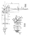
- a device 1 generally comprises a light source S generating a light source beam FS.
- a first optical assembly 2 produces an incident beam FI from the source beam FS.
- This incident beam FI penetrates inside a homogeneous transparent medium 3 having a bearing surface on which the fingerprint ED of a finger D is in contact.
- the beam incident FI is reflected on this bearing surface according to a reflected beam FR which enters a second optical device 4 which forms an image ED2 of the fingerprint ED.
- This ED2 image is received on a receiver 5.
- FIG. 2 a first embodiment of the device according to the invention.
- the arrangement of the various constituent elements of this device, represented in this FIG. 2, is that used by the applicant for the development of the invention.
- the numerical values provided below are of course only for information. They are also provided with an average relative uncertainty of around 5%. It goes without saying that this first embodiment of the device makes it possible to illustrate the general principle of the invention.
- the light source S is a light-emitting diode of the type manufactured by the Japanese company STANLEY. This light emitting diode has an opening angle of 9 degrees and emits a wave whose wavelength is between about 0.62 and about 0.71 microns. This light source therefore has a narrow spectrum.
- a light emitting diode is particularly advantageous in this application compared to laser diodes for example. Indeed the latter are sensitive to sudden variations in the voltage of their power supply which can destroy them and it is therefore necessary to conceive a stabilized power supply for the use of such laser diodes. In addition, their output power depends on the temperature and their lifetime decreases exponentially with increasing temperature. It is therefore necessary to further provide a temperature stabilization system. These precautions for use have led the Applicant to prefer the use of a light-emitting diode which is easy to use, very resistant and consumes little.
- the first optical device 2 comprises a first converging spherical lens 20 with a diameter of 2.4 cm, the optical center of which is located 9 cm from the light source S and the focal distance of which is 2 cm.
- the first optical device 2 also comprises a second converging spherical lens 21, with a diameter of 4 cm, located 8.5 cm from the first converging lens 20. Its focal distance is 5 cm.
- the source beam FS arriving on the first converging lens 20 converges at a point A constituting a substantially point auxiliary source. This auxiliary source A is located 2.6 cm from the optical center of the first spherical lens 20.
- the distance separating the auxiliary source A from the optical center of the second spherical lens 21 is greater than the focal distance of the latter.
- the reasons for this arrangement will be explained below.
- the optical device 2 therefore produces at the output of the second spherical lens 21 the incident beam FI.
- the light source S and the respective optical centers of the first and second converging lenses are aligned along a first optical axis 01.
- the transparent homogeneous medium 3 is a prism of right-angled triangular cross section whose two intersecting perpendicular sides respectively constitute an input diopter 30 and an output diopter 32.
- the side joining the two perpendicular sides 30 and 32 constitutes the bearing surface 31 on which the ED fingerprint is in contact.
- the optical axis 01 is substantially perpendicular to the plane dioptre 30 and the bearing surface 31 is inclined at an angle of 45 degrees relative to this optical axis 01.
- the point of competition 0 of the optical axis 01 and the bearing surface 31 is located at 4 cm from the optical center of the second converging spherical lens 21.
- This prism is made of glass with an optical index equal to approximately 1.5.
- the bearing surface 31 of the prism is large enough to be able to support the finger D.
- the second optical device 4 Downstream of this prism is the second optical device 4.
- This second optical device comprises a Convergent cylindrical lens 40, located 3.5 cm from point 0, the longitudinal geometric axis of which is substantially orthogonal to the optical plane.
- This cylindrical lens will therefore act only on an object situated in a plane parallel to the optical plane, and will have no effect on an object situated in a plane perpendicular to this optical plane.
- the cylindrical lens 40 has a focal distance of 8 cm, greater than the maximum distance separating its optical axis from the relief surface, and provides a virtual image ED1.
- the second optical device 4 also comprises downstream of this cylindrical lens 40, a converging spherical lens 41 whose optical center is located 10 cm from the cylindrical lens 40.
- This spherical lens has a focal distance of 4 cm, and a diameter of 3.15 cm.
- the optical center of this spherical lens is of course located on the optical axis 02 which also intersects the optical axis of the cylindrical lens 40.
- This spatial filter consists of a slit-shaped mask of adjustable width which can go up to 3 mm and a height of 1 cm. The height being of course a dimension taken in the plane perpendicular to the optical plane. The plane of this slot is located 4.3 cm from the optical center of the converging spherical lens 41.
- the image ED2 of the fingerprint ED formed by this second optical device is in a plane whose point of intersection with the optical axis 02 is approximately 5.5 cm from the optical center of the converging spherical lens 41.
- the trace of the plane of the image ED2 on the optical plane is inclined by an angle a .
- a CCD matrix 50 forming part of a conventional CCD receiver.
- the dimensions of this CCD matrix are approximately 8.8 mm x 6.6 mm.
- the light-emitting diode S therefore sends the source beam FS on the first converging spherical lens 20.
- the light-emitting diode is not a coherent source, but, by compared to filament lamps, the light beam emitted is very directive and of limited spectrum.
- the spherical lens 20 makes the source beam converge at a point A which thus constitutes a substantially point source from which the incident beam FI comes. As point A is located at a distance greater than the focal distance of the spherical lens 21, the incident beam FI is slightly convergent at the output of the first optical device 2.
- the light source has the advantage of being economical and of not requiring the precautions for use explained above for the laser diodes, it has another advantage compared to the laser diodes.
- the source beam of the latter is divergent and asymmetrical. There is also an elliptical section, depending on the models used, this divergence can vary between 10 x 25 degrees and 30 x 40 degrees. It is therefore necessary to use wide aperture lenses to create a substantially point source which can be disadvantageous in particular for the bulk.
- the fingerprint ED has a succession of recesses CED and projections SED.
- the projections SED are in contact with the bearing surface 31 while the recesses are not.
- a glass-air interface is therefore obtained, whereas at the level of the projections of this fingerprint, a glass-skin interface is obtained.
- the inclination of the bearing face 31, the angle of incidence of the incident beam FI and the refraction index of the prism are such that a part FI1 of the incident beam FI arriving on the bearing surface at level d '' a glass-air interface is totally reflected in a reflected beam chi FR1.
- a part FI2 of the incident beam FI arriving on the bearing face in contact with a glass-skin interface is partly, or even totally, absorbed into the skin, thus creating a reflected beam FR2 having much less light intensity than the FR1 beam.
- All of these beams FR1 and FR2 comprise an EDO pattern corresponding to the fingerprint ED and obtained by reflection of the incident beam on the bearing surface. This EDO pattern has an anamorphosis due to the inclination of the support surface.
- All of the beams FR1 and FR2 after passing through the optical device 4, not shown in FIG. 3, will form the image ED2 which will be a succession of dark areas, corresponding to the projections of the fingerprint, and clear, corresponding in the hollow of the fingerprint.
- the EDO pattern corresponding to the ED fingerprint has an anamorphosis, that is to say compression in the optical plane.
- the purpose of the cylindrical lens 40 is therefore to correct this anamorphosis and to produce an ED1 image in which the correct proportions are restored.
- the spherical lens 41 makes it possible in combination with the cylindrical lens 40 to carry out on the one hand the development of the image ED2 and so that the latter is real and compatible with the dimensions of the CCD matrix 50 and on the other hand to straighten the plane of the image ED2 in a direction tending to make it practically parallel to the cross section of the reflected beam which reaches it.
- an angle a equal to about 3.5 degrees.
- the function of the spatial filter 42 introduced between the cylindrical lens and the spherical lens makes it possible to limit the aberrations of sphericity of the beam and allows a gain in sharpness and in contrast of the image ED2.
- the cylindrical lens 40 and the spherical lens 41 constitute correction means capable of compensating for the anamorphosis of the used EDO pattern. born by the inclination of the bearing surface 31 and adapted to straighten the image plane as explained above. Given the geometry used, relatively short focal lengths have been chosen for the cylindrical 40 and spherical 41 lenses. This straightening of the plane of the image upon focusing therefore makes it possible to reduce the tilt a of the receiver 5 and d 'increase the image quality, note that this quality is further improved with a slightly oily fingerprint.
- the spherical lens 20 and the spherical lens 21 of the first optical device 2 constitute means of convergence suitable firstly for making the incident beam converge at point A so as to create a substantially point source and secondly suitable for creating a the incident beam advantageously slightly convergent.
- FIG. 4 we see that there is shown a second embodiment of the device according to the invention for housing it in a compact housing.
- elements analogous or having functions analogous to those represented in FIG. 2 have references, either increased by 100, or assigned with a ', with respect to those they had in FIG. 2. Only the differences between these two figures will be described.
- the first optical device further comprises a total reflection prism 22 interposed between the light source S ′ and the lens 120 as well as another total reflection prism 23 interposed between the lenses 120 and 121.
- the second optical device 4 comprises in the same way, moreover, a total reflection prism 43 interposed between the cylindrical lens 140 and the spatial filter 142.
- the prisms 22 and 23 constitute first return means and the prism 43 constitutes second return means.
- the invention may include variants including the following: -
- the Applicant has observed that the use of such a laser source creates a greater contrast than that caused by the light-emitting diode.
- the Applicant therefore prefers to use the light-emitting diode which gives a lower contrast while being largely sufficient since the background noise of the light source is limited, and which does not require the precautions of job described above.
- the light source can be made up of a laser source if the constraints of use are not considered to be penalizing, - lenses of different focal lengths can be chosen, their mutual arrangement then having to be modified; - the receiver is not limited to a CCD matrix.
Landscapes
- Engineering & Computer Science (AREA)
- Physics & Mathematics (AREA)
- Health & Medical Sciences (AREA)
- Life Sciences & Earth Sciences (AREA)
- Human Computer Interaction (AREA)
- General Physics & Mathematics (AREA)
- Medical Informatics (AREA)
- Animal Behavior & Ethology (AREA)
- Biomedical Technology (AREA)
- Heart & Thoracic Surgery (AREA)
- Biophysics (AREA)
- Molecular Biology (AREA)
- Surgery (AREA)
- Pathology (AREA)
- General Health & Medical Sciences (AREA)
- Public Health (AREA)
- Veterinary Medicine (AREA)
- Optics & Photonics (AREA)
- Multimedia (AREA)
- Theoretical Computer Science (AREA)
- Image Input (AREA)
Applications Claiming Priority (2)
| Application Number | Priority Date | Filing Date | Title |
|---|---|---|---|
| FR8802803 | 1988-03-04 | ||
| FR8802803A FR2628221B1 (fr) | 1988-03-04 | 1988-03-04 | Dispositif de formation d'une image d'une surface en relief, notamment une empreinte digitale |
Publications (1)
| Publication Number | Publication Date |
|---|---|
| EP0361987A1 true EP0361987A1 (de) | 1990-04-04 |
Family
ID=9363931
Family Applications (1)
| Application Number | Title | Priority Date | Filing Date |
|---|---|---|---|
| EP89400587A Withdrawn EP0361987A1 (de) | 1988-03-04 | 1989-03-02 | Vorrichtung zur Abbildung einer Reliefoberfläche, insbesondere eines Fingerabdruckes |
Country Status (2)
| Country | Link |
|---|---|
| EP (1) | EP0361987A1 (de) |
| FR (1) | FR2628221B1 (de) |
Cited By (5)
| Publication number | Priority date | Publication date | Assignee | Title |
|---|---|---|---|---|
| EP0472769A1 (de) * | 1990-08-30 | 1992-03-04 | Maurer Identifikationssysteme Gmbh | Identifikationseinrichtung für Daumen- oder Fingerabdrücke |
| GB2276732A (en) * | 1993-03-31 | 1994-10-05 | Central Research Lab Ltd | Fingerprint imaging |
| WO2001022032A1 (en) * | 1999-09-23 | 2001-03-29 | Lawrence Mullaney | Measuring relief imaged printing plates |
| WO2001031563A1 (en) * | 1999-10-28 | 2001-05-03 | Guardware Systems Informatikai Kft. | Objective lens system |
| WO2020151159A1 (zh) * | 2019-01-22 | 2020-07-30 | 深圳市汇顶科技股份有限公司 | 指纹识别的装置和电子设备 |
Citations (3)
| Publication number | Priority date | Publication date | Assignee | Title |
|---|---|---|---|---|
| EP0045915A1 (de) * | 1980-08-11 | 1982-02-17 | Siemens Aktiengesellschaft | Fingerabdrucksensor zum Erzeugen eines dem topografischen Relief eines zu untersuchenden Fingers entsprechenden Ausgangssignals |
| EP0045913A1 (de) * | 1980-08-11 | 1982-02-17 | Siemens Aktiengesellschaft | Fingerabdrucksensor zum Erzeugen eines dem topografischen Relief eines zu untersuchenden Fingers entsprechenden elektrischen Signals |
| DE3421220A1 (de) * | 1984-06-07 | 1985-12-12 | Guenther Mull | Vorrichtung zur abbildung von schiefwinklig zur abbildungsebene angeordneten gegenstaenden |
-
1988
- 1988-03-04 FR FR8802803A patent/FR2628221B1/fr not_active Expired - Lifetime
-
1989
- 1989-03-02 EP EP89400587A patent/EP0361987A1/de not_active Withdrawn
Patent Citations (3)
| Publication number | Priority date | Publication date | Assignee | Title |
|---|---|---|---|---|
| EP0045915A1 (de) * | 1980-08-11 | 1982-02-17 | Siemens Aktiengesellschaft | Fingerabdrucksensor zum Erzeugen eines dem topografischen Relief eines zu untersuchenden Fingers entsprechenden Ausgangssignals |
| EP0045913A1 (de) * | 1980-08-11 | 1982-02-17 | Siemens Aktiengesellschaft | Fingerabdrucksensor zum Erzeugen eines dem topografischen Relief eines zu untersuchenden Fingers entsprechenden elektrischen Signals |
| DE3421220A1 (de) * | 1984-06-07 | 1985-12-12 | Guenther Mull | Vorrichtung zur abbildung von schiefwinklig zur abbildungsebene angeordneten gegenstaenden |
Cited By (7)
| Publication number | Priority date | Publication date | Assignee | Title |
|---|---|---|---|---|
| EP0472769A1 (de) * | 1990-08-30 | 1992-03-04 | Maurer Identifikationssysteme Gmbh | Identifikationseinrichtung für Daumen- oder Fingerabdrücke |
| GB2276732A (en) * | 1993-03-31 | 1994-10-05 | Central Research Lab Ltd | Fingerprint imaging |
| GB2276732B (en) * | 1993-03-31 | 1995-12-13 | Central Research Lab Ltd | Fingerprint imaging |
| WO2001022032A1 (en) * | 1999-09-23 | 2001-03-29 | Lawrence Mullaney | Measuring relief imaged printing plates |
| WO2001031563A1 (en) * | 1999-10-28 | 2001-05-03 | Guardware Systems Informatikai Kft. | Objective lens system |
| US6934089B1 (en) | 1999-10-28 | 2005-08-23 | Guardware Systems Informatikai Kft. | Objective lens system |
| WO2020151159A1 (zh) * | 2019-01-22 | 2020-07-30 | 深圳市汇顶科技股份有限公司 | 指纹识别的装置和电子设备 |
Also Published As
| Publication number | Publication date |
|---|---|
| FR2628221B1 (fr) | 1990-08-10 |
| FR2628221A1 (fr) | 1989-09-08 |
Similar Documents
| Publication | Publication Date | Title |
|---|---|---|
| EP0644411B1 (de) | Verfahren und Gerät zur absoluten Messung der geometrischen oder optischen Struktur eines optischen Bestandteiles | |
| US6038043A (en) | Method for recording a holographic optical element | |
| CH620535A5 (de) | ||
| EP0290347A2 (de) | Hochleistungsleuchte, insbesondere für Kraftfahrzeuge | |
| FR2642530A1 (fr) | Mecanisme de focalisation et tete optique | |
| FR2558971A1 (fr) | Appareil de formation d'images d'empreintes digitales | |
| WO2005006241A2 (fr) | Dispositif d'imagerie optique, destine notamment a la reconnaissance d'empreintes digitales. | |
| EP2443588B1 (de) | Bildgebungsvorrichtung mit prismenelement | |
| EP0022682B1 (de) | Optischer Lesekopf mit Halbleiter-Laserquelle und eine mit optischer Reflexion arbeitende Lesevorrichtung zum Lesen eines Informationsträgers, die einen solchen optischen Lesekopf enthält | |
| EP0361987A1 (de) | Vorrichtung zur Abbildung einer Reliefoberfläche, insbesondere eines Fingerabdruckes | |
| FR2677466A1 (fr) | Dispositif de detection de mise au point. | |
| EP0610640B1 (de) | Tragbarer Strichmarkierungsleser mit erweiterter Schärfentiefe | |
| EP0978085A1 (de) | Optoelektronisches bilderfassungsgerät, insbesondere für strichkodes | |
| EP3614305A1 (de) | Authentifizierung durch optischen index | |
| EP4139657A1 (de) | Vorrichtung zur lichtverteilung mittels beugungsgittern | |
| WO2005038698A1 (fr) | Dispositif optique de formation d'une image d'empreintes digitales | |
| EP3916441A1 (de) | Lichtverteilungsvorrichtung auf basis eines planaren wellenleiters | |
| EP0375492A1 (de) | Optische Vorrichtung für das Beobachten eines ausgedehnten Objektes | |
| EP4105897B1 (de) | Vorrichtung zur biometrischen erfassung | |
| EP1077641A1 (de) | Optischer sensor fuer kompakten digitalen fingerabdruck | |
| EP1665122B1 (de) | Optische einrichtung zur bildung eines fingerabdruckbildes | |
| JPH03244092A (ja) | 指紋画像入力装置 | |
| FR2678394A1 (fr) | Dispositif de detection de mise au point. | |
| EP2927577B1 (de) | Beleuchtungsoptik für biometrische messvorrichtung | |
| FR2768526A1 (fr) | Dispositif electro-optique, pour la lecture de caracteres sur un support, en particulier un code a barres |
Legal Events
| Date | Code | Title | Description |
|---|---|---|---|
| PUAI | Public reference made under article 153(3) epc to a published international application that has entered the european phase |
Free format text: ORIGINAL CODE: 0009012 |
|
| AK | Designated contracting states |
Kind code of ref document: A1 Designated state(s): DE GB IT |
|
| 17P | Request for examination filed |
Effective date: 19900705 |
|
| 17Q | First examination report despatched |
Effective date: 19920803 |
|
| STAA | Information on the status of an ep patent application or granted ep patent |
Free format text: STATUS: THE APPLICATION IS DEEMED TO BE WITHDRAWN |
|
| 18D | Application deemed to be withdrawn |
Effective date: 19921215 |