EP0362034A1 - Dispositif pour positionner des bandes sur une vitre ou panneau similaire - Google Patents
Dispositif pour positionner des bandes sur une vitre ou panneau similaire Download PDFInfo
- Publication number
- EP0362034A1 EP0362034A1 EP89402602A EP89402602A EP0362034A1 EP 0362034 A1 EP0362034 A1 EP 0362034A1 EP 89402602 A EP89402602 A EP 89402602A EP 89402602 A EP89402602 A EP 89402602A EP 0362034 A1 EP0362034 A1 EP 0362034A1
- Authority
- EP
- European Patent Office
- Prior art keywords
- strip
- tool
- roller
- base member
- corner
- Prior art date
- Legal status (The legal status is an assumption and is not a legal conclusion. Google has not performed a legal analysis and makes no representation as to the accuracy of the status listed.)
- Withdrawn
Links
Images




Classifications
-
- B—PERFORMING OPERATIONS; TRANSPORTING
- B29—WORKING OF PLASTICS; WORKING OF SUBSTANCES IN A PLASTIC STATE IN GENERAL
- B29C—SHAPING OR JOINING OF PLASTICS; SHAPING OF MATERIAL IN A PLASTIC STATE, NOT OTHERWISE PROVIDED FOR; AFTER-TREATMENT OF THE SHAPED PRODUCTS, e.g. REPAIRING
- B29C63/00—Lining or sheathing, i.e. applying preformed layers or sheathings of plastics; Apparatus therefor
- B29C63/0026—Lining or sheathing, i.e. applying preformed layers or sheathings of plastics; Apparatus therefor an edge face with strip material, e.g. a panel edge
- B29C63/003—Lining or sheathing, i.e. applying preformed layers or sheathings of plastics; Apparatus therefor an edge face with strip material, e.g. a panel edge continuously
-
- B—PERFORMING OPERATIONS; TRANSPORTING
- B29—WORKING OF PLASTICS; WORKING OF SUBSTANCES IN A PLASTIC STATE IN GENERAL
- B29C—SHAPING OR JOINING OF PLASTICS; SHAPING OF MATERIAL IN A PLASTIC STATE, NOT OTHERWISE PROVIDED FOR; AFTER-TREATMENT OF THE SHAPED PRODUCTS, e.g. REPAIRING
- B29C63/00—Lining or sheathing, i.e. applying preformed layers or sheathings of plastics; Apparatus therefor
- B29C63/0026—Lining or sheathing, i.e. applying preformed layers or sheathings of plastics; Apparatus therefor an edge face with strip material, e.g. a panel edge
-
- E—FIXED CONSTRUCTIONS
- E06—DOORS, WINDOWS, SHUTTERS, OR ROLLER BLINDS IN GENERAL; LADDERS
- E06B—FIXED OR MOVABLE CLOSURES FOR OPENINGS IN BUILDINGS, VEHICLES, FENCES OR LIKE ENCLOSURES IN GENERAL, e.g. DOORS, WINDOWS, BLINDS, GATES
- E06B3/00—Window sashes, door leaves, or like elements for closing wall or like openings; Layout of fixed or moving closures, e.g. windows in wall or like openings; Features of rigidly-mounted outer frames relating to the mounting of wing frames
- E06B3/66—Units comprising two or more parallel glass or like panes permanently secured together
- E06B3/673—Assembling the units
- E06B3/67326—Assembling spacer elements with the panes
- E06B3/6733—Assembling spacer elements with the panes by applying, e.g. extruding, a ribbon of hardenable material on or between the panes
-
- E—FIXED CONSTRUCTIONS
- E06—DOORS, WINDOWS, SHUTTERS, OR ROLLER BLINDS IN GENERAL; LADDERS
- E06B—FIXED OR MOVABLE CLOSURES FOR OPENINGS IN BUILDINGS, VEHICLES, FENCES OR LIKE ENCLOSURES IN GENERAL, e.g. DOORS, WINDOWS, BLINDS, GATES
- E06B3/00—Window sashes, door leaves, or like elements for closing wall or like openings; Layout of fixed or moving closures, e.g. windows in wall or like openings; Features of rigidly-mounted outer frames relating to the mounting of wing frames
- E06B3/66—Units comprising two or more parallel glass or like panes permanently secured together
- E06B3/673—Assembling the units
- E06B3/67365—Transporting or handling panes, spacer frames or units during assembly
- E06B2003/67378—Apparatus travelling around the periphery of the pane or the unit
-
- Y—GENERAL TAGGING OF NEW TECHNOLOGICAL DEVELOPMENTS; GENERAL TAGGING OF CROSS-SECTIONAL TECHNOLOGIES SPANNING OVER SEVERAL SECTIONS OF THE IPC; TECHNICAL SUBJECTS COVERED BY FORMER USPC CROSS-REFERENCE ART COLLECTIONS [XRACs] AND DIGESTS
- Y10—TECHNICAL SUBJECTS COVERED BY FORMER USPC
- Y10T—TECHNICAL SUBJECTS COVERED BY FORMER US CLASSIFICATION
- Y10T156/00—Adhesive bonding and miscellaneous chemical manufacture
- Y10T156/17—Surface bonding means and/or assemblymeans with work feeding or handling means
- Y10T156/1788—Work traversing type and/or means applying work to wall or static structure
-
- Y—GENERAL TAGGING OF NEW TECHNOLOGICAL DEVELOPMENTS; GENERAL TAGGING OF CROSS-SECTIONAL TECHNOLOGIES SPANNING OVER SEVERAL SECTIONS OF THE IPC; TECHNICAL SUBJECTS COVERED BY FORMER USPC CROSS-REFERENCE ART COLLECTIONS [XRACs] AND DIGESTS
- Y10—TECHNICAL SUBJECTS COVERED BY FORMER USPC
- Y10T—TECHNICAL SUBJECTS COVERED BY FORMER US CLASSIFICATION
- Y10T156/00—Adhesive bonding and miscellaneous chemical manufacture
- Y10T156/18—Surface bonding means and/or assembly means with handle or handgrip
-
- Y—GENERAL TAGGING OF NEW TECHNOLOGICAL DEVELOPMENTS; GENERAL TAGGING OF CROSS-SECTIONAL TECHNOLOGIES SPANNING OVER SEVERAL SECTIONS OF THE IPC; TECHNICAL SUBJECTS COVERED BY FORMER USPC CROSS-REFERENCE ART COLLECTIONS [XRACs] AND DIGESTS
- Y10—TECHNICAL SUBJECTS COVERED BY FORMER USPC
- Y10T—TECHNICAL SUBJECTS COVERED BY FORMER US CLASSIFICATION
- Y10T29/00—Metal working
- Y10T29/53—Means to assemble or disassemble
- Y10T29/53657—Means to assemble or disassemble to apply or remove a resilient article [e.g., tube, sleeve, etc.]
Definitions
- the present invention relates to an apparatus for laying an adhesive strip along the peripheral edges of a glass sheet or other member positioned on a work table with a view to forming a double-glazed insulated glass panel.
- One conventional method of making a double-glazed insulated glass panel consists of manually applying an adhesive strip along the peripheral edges of a glass sheet and then positioning a second glass thereupon to form the panel.
- Swiggle Strip is an extruded butyl-based material of a thermo-plastic compound which contains a corrugated aluminum spacer and molecular sieve desiccant.
- the corrugation which extends in a plane perpendicular to that of the glass sheets, lends strength to the spacer to withstand forces which the glass sheets would receive during fabrication, shipping, glazing and servicing.
- the application of an extruded butyl-based strip allows a continuous strip to be applied along all the sides of the panels uninterruptedly, including the corners.
- the manual application of a continuous strip to the glass sheet requires considerable ability on the part of the installer, especially at the corners.
- a tool for applying a strip of material to a surface of a glass sheet or other member adjacent to the periphery thereof, wherein the glass sheet is adapted to be supported on a support surface comprises means for slidably supporting a base member of the tool on a support surface; guide means for guiding the base member along a peripheral edge of the glass pane or member; a body supported on the base member, and at least one roller means associated with the tool for guiding a strip of material around corners of the glass sheet or other member.
- an apparatus which comprises, in its broadest aspect, a handle; first support means at one end of the handle, including means for contacting the work table on which a glass sheet is positioned; a housing mounted at the opposite end of the handle; second support means mounted to the housing, including means for contacting the work table; and strip receiving and applying means operatively associated with the housing, including roller means contacting one side of the strip to be laid; roller means contacting the strip along the top edge thereof and applying pressure thereon as it is being laid on the glass sheet; and means adapted to cooperate with the roller means for applying the strip at corners of the glass sheet.
- adjusting means are provided for varying the roller means for differentsizes of strips or varying tolerances between the side of the glass sheet and the strip.
- a pivoted latch member is engaged with the corner of the member when a corner is reached, and acts as a pivot or hinge for movement of the base member around the corner, without removing the tool from the working surface, the strip being bent and applied at the corner. The tool is then used to continue application of the strip along another length of the edge.
- the device most desirably uses means for positioning the strip which has a downward sliding action as well as a forward one.
- the means for positioning the strip comprise at least one roller, having an axis extending upward, with a slight inclined and forward position in the direction of the movement of the tool in combination with means for positioning the strip.
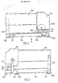
- FIG. 1 there is shown a glass sheet 10 placed on a work table 12 so that an adhesive strip 14 may be laid along the peripheral edges thereof.
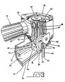
- the apparatus of the present invention comprises a horizontally extending handle 18 displaying a cylindrical body having at one end thereof an inlet port 20 for connection to an air supply (not shown) through appropriate conduit 22.
- This end of the handle 18 is supported by a vertically extending element 24, equipped at the lower end thereof with a roller 26 adapted to roll along the work table 12.
- a manually operable lever 28 allows access of air from the supply source to a housing 30 mounted to the opposite end of the handle 18.
- Housing 30 is supported on the work table 12 by a vertically extending element 32 that has a base portion 34 and a roller 36 for rolling on and thereby contacting the work table 12. Relative positioning of the housing 30 on the element 32 is accomplished by means of a nut 38 adapted to slide in a vertical slot 40.
- rollers 42, 44, 46 are mounted to housing 30 and together combine for the application of the adhesive 14 along the peripheral edges of the glass sheet 10.
- Rollers 42 and 46 have parallel vertically extending axes which are rotatably driven by the air supplied through the handle 18 while roller 44, the axis of which extends perpendicular to the axes of rollers 42 and 46, is freely rotatable.
- Roller 42 is mounted on a shaft 48 which is connected to a drive gear arrangement 50, 52, while roller 46 is driven by means of second gear arrangement 54, 56, receiving torque from shaft 48.
- Shaft 60 transmits this torque to the roller 46.
- the shaft (not shown) of the roller 44 is supported by a side member 62 of the housing 30.
- the height of roller 44 may be adjusted by means of plate 64 having fastening means 66 slidably mounted in slots 68.
- a base plate 70 is secured by means of screws 72 to the base portion 34 of the housing.
- the base plate 70 has a pair of side faces 74 and 76 which are adapted to contact the side edge of a glass sheet.
- the base portion 34 as well as the base plate 70 each have a central opening through which extends the roller 42.
- the bottom wall 78 of the roller 42 extends in a plane which extends slightly above the bottom wall of the base plate 70; the space between the bottom walls corresponds substantially to the thickness of the glass sheet 10 with a small tolerance, so that the bottom wall 78 is slightly above the top face of the glass sheet 10.
- the height of roller 42 is adjusted by means of a chuck collet 80 mounted to the shaft 48.
- the bottom wall 82 of roller 46 extends in the same plane as that of the bottom wall 78 of roller 42.
- roller 42 is the main drive roller while roller 44 serves to apply a pressure on the strip 14 to secure it to the glass sheet.
- Roller 46 named the cornering roller, is used principally when, during the application of the adhesive strip 14, a corner of the glass sheet is reached.
- the main drive roller 42 is rendered idle during the cornering operation. Referring to Figure 4, the idling is achieved by means of element 84 which blocks rotation of shaft 48.
- the assembled glass panel 86 is shown consisting of a pair of glass sheets 10 and 10′ with the adhesive strip 14 extending between the peripheral edges thereof and securing same together.
- a preferred adhesive strip is the one known under the trademark "Swiggle” Strip", which is formed of an extruded butyl-based strip, and contains a corrugated aluminum spacer 88 to withstand the forces applied perpendicularly to the planes of the glass sheets 10 and 10′.
- the three rollers 42, 44 and 46 are made of plastic material, while the base plate 70 (including its side faces 74 and 76) is preferably made of nylon.
- a tool comprises a base member 110 which is supported from a support surface by rollers 111.
- a body 114 mounted on the base member 110 by supports 112 and 113 is a body 114 adapted to be gripped by the hand of an operator.
- rollers 116 and 117 At the forward end of the body is a housing 115 and extending from the bottom of the housing, being rotatably supported therein, are two rollers 116 and 117, the rollers 116 and 117 rotating about axes which are generally vertical, although, as described later, some departure from the vertical can be provided. Rollers 116 and 117 are spaced apart laterally, in a direction normal to the length of the base member 10, to define an area where a strip of material travels. Positioned between the rollers 116 and 117 is a further, thin roller 118, rotatably mounted in the housing 115 for rotation about a generally horizontal axis extending transversely.
- rollers 120 Mounted on the bottom surface of the base member 10 are rollers 120. These rollers rotate about vertical axes and position the tool relative to the edge of the article onto which the strip is to be applied, for example, a sheet of glass 125. This can be seen in Figure 9a, in which a sheet of glass 125 is shown, supported on a support member 126.
- the rollers 120 position the tool, and thus, the rollers 16 and 117, relative to the edge 127 of the glass or other member 125.
- the rollers 120 can be positioned so that a strip is positioned on the member 125 with its outer surface aligned with the edge 127, or preferably positioned a small distance inward or outward from the edge 127.
- the strip may be applied so as to overlie the edge where it is desired to use the strip in conjunction with a further component or device for sealing the edge of a window.
- the position of the rollers 116 and 117 relative to the rollers 120 can be determined so as to position the strip as desired relative to the edge 127.
- Rollers 116 and 117 are usually positioned apart very slightly more than the width of a strip, and they may be positioned less than the thickness of the strip to provide a compression force to the strip.
- the roller 118 is positioned from the top surface 130 of the member 125 such that it presses down slightly on the strip to ensure adhesion to the member 125.
- a strip is shown in dotted outline at 131 in Figure 9a.
- the strip is initially positioned with its end on the glass pane or other member 125.
- the front of the tool is applied to the edge 127 of the glass 125 and moved along the edge 127 of the member 125, the rollers 116 and 117 engaging over the end of the strip, and then continuing to guiding the strip relative to the edge 127, a roller 118 pressing the strip into firm contact therewith.
- rollers 116 and 117 inclined at a very small angle, as viewed from the side. This is illustrated in Figure 10.
- the front end of the tool would be to the right, so that the rollers 116 and 117 have a forward and inclined position. This assists in pushing the strip down into contact with the surface of the article.
- This inclination is conveniently obtained by inclining the body 114, as indicated in dotted outline in Figure 6. This also helps to overcome any tendency of the tool to lift at the front.
- a member which locates the tool relative to a corner is provided. This is illustrated particularly in Figures 11 and 12, and also in Figure 13.
- a corner location member 135 is shown in its withdrawn or normal position.
- the member 135 comprises two flanges 136 and 137 at right angles, the member being pivotally mounted at 138, on the base member 110, at a rear inner corner of the flange 136 but this may be varied as desired.
- the member 135 is biased to the withdrawn position by a spring 145.
- a spring 145 At the front edge of flange 136, there extends an arm 139 which extends first forwardly, and then sideways, finishing in a hooked formation 140.
- the member 135 and its flange 137 are as shown in Figure 11, with the hooked formation 140 withdrawn out of contact with the glass or other member 125.
- the member 137 Figure 13
- the hooked formation 140 passes the corner, extending outwardly, and the hooked formation 140 is then out of contact with the edge 127 of the glass 125.
- the tool is then pivoted around the corner, the roller 116 acting as a pivot point and being held in a band of the strip.
- the hooked formation 140 and the front roller 120 which have initially passed the corner and are out of contact with the edge 127 of the glass 125, are moved around into contact with the next edge 127 of the glass 125.
- the flange 137 is then released, allowing member 135 and hooked formation 140 to retract.
- the next two rollers 120 move out of contact with the glass edge 127 to which the strip has been applied, and become aligned with the next edge, moving into contact with the next edge of the glass 125.
- a slight backward movement of the tool causes the hooked formation 140 to engage with the glass 125, as shown in Figure 12.
- Pressure is then briefly exerted on the body 114 of the tool in order to ensure that the strip is firmly applied at the corner of the glass or other member 125.
- the strip is pulled lightly, preferably at an angle relative to the next edge 127 of the glass 125, then generally aligned with the next edge 127.
- the glass 125 is moved around to bring the next edge length to the front so that the tool may subsequently progress along the next edge 127.
- While the tool has been described as being used for polygonal shaped panes, or other members, it can also be used to apply strip to curved edges or peripheries. For effective positioning of the strip, it would be useful to stretch the strip slightly as it is applied. If the strip is not stretched, the outer surface will be under tension as it will take a longer path than the inner surface, and gradually this will cause the strip to move inwards slightly. This can be overcome by an initial stretching, as by providing a suitably inclined roller.
- edge 127 of the pane of glass or other member 125 need not be at right angles to the surface of the member. If, for any reason, the glass edge 127 is bevelled, then the rollers 120 may, if desired, have a peripheral profile to match.
- the tool is also equally applicable to members 125 having rounded edges 127.
- a power drive can be provided for one or more of the rollers 111, rollers 120, or a combination thereof. Power drive can also be applied to the rollers 116, 117 and 118.
- a tool as described above can readily apply a strip at the peripheral edge of such a member.
- Strip can also be applied to surfaces which are inclined relative to the support surfaces.
- the strip would be formed with a contact surface which is inclined to match the inclination of the surface to which it is to be applied.
- the relative length of the rollers 116 and 117 would be different, and roller 117 may have to be of a smaller diameter.
Landscapes
- Engineering & Computer Science (AREA)
- Manufacturing & Machinery (AREA)
- Civil Engineering (AREA)
- Structural Engineering (AREA)
- Joining Of Glass To Other Materials (AREA)
- Adhesives Or Adhesive Processes (AREA)
Applications Claiming Priority (2)
| Application Number | Priority Date | Filing Date | Title |
|---|---|---|---|
| CA578349 | 1988-09-23 | ||
| CA000578349A CA1325410C (fr) | 1988-09-23 | 1988-09-23 | Outil pour la pose de bande adhesive en peripherie de panneau de vitrage |
Publications (1)
| Publication Number | Publication Date |
|---|---|
| EP0362034A1 true EP0362034A1 (fr) | 1990-04-04 |
Family
ID=4138782
Family Applications (1)
| Application Number | Title | Priority Date | Filing Date |
|---|---|---|---|
| EP89402602A Withdrawn EP0362034A1 (fr) | 1988-09-23 | 1989-09-22 | Dispositif pour positionner des bandes sur une vitre ou panneau similaire |
Country Status (3)
| Country | Link |
|---|---|
| US (2) | US5013377A (fr) |
| EP (1) | EP0362034A1 (fr) |
| CA (1) | CA1325410C (fr) |
Cited By (6)
| Publication number | Priority date | Publication date | Assignee | Title |
|---|---|---|---|---|
| WO1998055725A1 (fr) * | 1997-06-02 | 1998-12-10 | Luc Lafond | Outil a main pour appliquer des bandes, comportant un dispositif a former les coins |
| CN1313268C (zh) * | 2002-10-25 | 2007-05-02 | Afg工业公司 | 用于在玻璃或类似材料上布置密封胶隔条的手动施加工具 |
| USD735010S1 (en) | 2013-07-08 | 2015-07-28 | 3M Innovative Properties Company | Window film attachment applicator tool |
| USD735009S1 (en) | 2013-07-08 | 2015-07-28 | 3M Innovative Properties Company | Cutting plate for a window film attachment applicator tool |
| USD762438S1 (en) | 2013-07-08 | 2016-08-02 | 3M Innovative Properties Company | Window film attachment applicator tool |
| IT201900019810A1 (it) * | 2019-10-25 | 2021-04-25 | Antonio Perri | Dispositivo per applicazione di nastro |
Families Citing this family (31)
| Publication number | Priority date | Publication date | Assignee | Title |
|---|---|---|---|---|
| US5975181A (en) * | 1991-06-03 | 1999-11-02 | Lafond; Luc | Strip applying hand tool with corner forming apparatus |
| US6030475A (en) * | 1995-10-23 | 2000-02-29 | Billco Manufacturing Inc. | System for and method of applying a sealant strip to sheet material |
| US5779830A (en) * | 1995-10-24 | 1998-07-14 | Truseal Technologies, Inc. | Flexible tape applicator and method of operation |
| CA2200024C (fr) * | 1997-03-14 | 2001-05-22 | Stephen Field | Fabrication d'unites de verre isolant |
| US6360804B1 (en) | 1997-03-14 | 2002-03-26 | Edgetech I.G. Inc. | Hand tool for adhesive strip application |
| US6193584B1 (en) | 1999-05-27 | 2001-02-27 | Read-Rite Corporation | Apparatus and method of device stripe height control |
| EP1138468A4 (fr) * | 1999-08-13 | 2002-04-10 | Asahi Glass Co Ltd | Procede et dispositif de fabrication d'une vitre avec cadre de resine |
| US6581341B1 (en) | 2000-10-20 | 2003-06-24 | Truseal Technologies | Continuous flexible spacer assembly having sealant support member |
| US7493739B2 (en) * | 2000-10-20 | 2009-02-24 | Truseal Technologies, Inc. | Continuous flexible spacer assembly having sealant support member |
| PL209386B1 (pl) | 2000-11-08 | 2011-08-31 | Agc Flat Glass North America | Ciągły giętki zespół dystansowy z żebrowanej rury |
| US7270859B2 (en) * | 2003-05-28 | 2007-09-18 | H.B. Fuller Licensing & Financing Inc. | Insulating glass assembly including a polymeric spacing structure |
| US7712503B2 (en) * | 2005-09-12 | 2010-05-11 | Billco Manufacturing Incorporated | Automatic flexible spacer or sealant applicator for a glass work piece and method of applying flexible spacer or sealant to a glass workpiece |
| US20090320406A1 (en) * | 2008-06-27 | 2009-12-31 | 3M Innovative Properties Company | Applicator tool |
| US8365495B1 (en) | 2008-11-20 | 2013-02-05 | Emseal Joint Systems Ltd. | Fire and water resistant expansion joint system |
| US10316661B2 (en) | 2008-11-20 | 2019-06-11 | Emseal Joint Systems, Ltd. | Water and/or fire resistant tunnel expansion joint systems |
| US9637915B1 (en) | 2008-11-20 | 2017-05-02 | Emseal Joint Systems Ltd. | Factory fabricated precompressed water and/or fire resistant expansion joint system transition |
| US9670666B1 (en) | 2008-11-20 | 2017-06-06 | Emseal Joint Sytstems Ltd. | Fire and water resistant expansion joint system |
| US11180995B2 (en) | 2008-11-20 | 2021-11-23 | Emseal Joint Systems, Ltd. | Water and/or fire resistant tunnel expansion joint systems |
| US9739050B1 (en) | 2011-10-14 | 2017-08-22 | Emseal Joint Systems Ltd. | Flexible expansion joint seal system |
| US9631362B2 (en) | 2008-11-20 | 2017-04-25 | Emseal Joint Systems Ltd. | Precompressed water and/or fire resistant tunnel expansion joint systems, and transitions |
| US10851542B2 (en) | 2008-11-20 | 2020-12-01 | Emseal Joint Systems Ltd. | Fire and water resistant, integrated wall and roof expansion joint seal system |
| US8341908B1 (en) | 2009-03-24 | 2013-01-01 | Emseal Joint Systems Ltd. | Fire and water resistant expansion and seismic joint system |
| US8813450B1 (en) | 2009-03-24 | 2014-08-26 | Emseal Joint Systems Ltd. | Fire and water resistant expansion and seismic joint system |
| US9068297B2 (en) | 2012-11-16 | 2015-06-30 | Emseal Joint Systems Ltd. | Expansion joint system |
| US9234381B2 (en) | 2013-01-07 | 2016-01-12 | WexEnergy LLC | Supplemental window for fenestration |
| US9663983B2 (en) | 2013-01-07 | 2017-05-30 | WexEnergy LLC | Frameless supplemental window for fenestration incorporating infiltration blockers |
| US9845636B2 (en) | 2013-01-07 | 2017-12-19 | WexEnergy LLC | Frameless supplemental window for fenestration |
| US10196850B2 (en) | 2013-01-07 | 2019-02-05 | WexEnergy LLC | Frameless supplemental window for fenestration |
| US10883303B2 (en) | 2013-01-07 | 2021-01-05 | WexEnergy LLC | Frameless supplemental window for fenestration |
| US9691163B2 (en) | 2013-01-07 | 2017-06-27 | Wexenergy Innovations Llc | System and method of measuring distances related to an object utilizing ancillary objects |
| AU2018278119B2 (en) | 2017-05-30 | 2023-04-27 | WexEnergy LLC | Frameless supplemental window for fenestration |
Citations (2)
| Publication number | Priority date | Publication date | Assignee | Title |
|---|---|---|---|---|
| DE8600068U1 (de) * | 1986-01-03 | 1986-02-13 | Ratiotechnik Rationalisierungstechnik und Automation GmbH u. Co KG, 3300 Braunschweig | Gerät zur Montage eines flexiblen Abstandhalters auf einer Glasscheibe |
| EP0293302A1 (fr) * | 1987-05-26 | 1988-11-30 | Tremco Ltd. | Outil pour l'application d'une bande d'espacement d'un vitrage isolant |
Family Cites Families (43)
| Publication number | Priority date | Publication date | Assignee | Title |
|---|---|---|---|---|
| US24937A (en) * | 1859-08-02 | Improvement in sewing-machines | ||
| US3037898A (en) * | 1957-05-17 | 1962-06-05 | Wabor A G Fa | Manufacture of floor coverings |
| US2916079A (en) * | 1957-12-18 | 1959-12-08 | Ernest H Schiefer | Portable hand tape folder |
| USRE24937E (en) * | 1959-04-30 | 1961-02-21 | Method for fabricating a carpet unit | |
| US3391805A (en) * | 1964-05-26 | 1968-07-09 | Sun Entpr Ltd | Apparatus for assembling glass sheets during manufacture of double glazed windows |
| US3677865A (en) * | 1970-05-01 | 1972-07-18 | Walter Wagner | Side delivery tape applicator |
| US3730815A (en) * | 1970-08-10 | 1973-05-01 | L Terzian | Tape applicator |
| US3733237A (en) * | 1971-10-20 | 1973-05-15 | Ppg Industries Inc | Apparatus for making hermetically sealed glazing units |
| US3951727A (en) * | 1972-07-06 | 1976-04-20 | Greenberg William B | Delaminating method and apparatus |
| US3879255A (en) * | 1972-10-18 | 1975-04-22 | Norton Co | Sealant hand applicator |
| FR2211413B1 (fr) * | 1972-12-21 | 1977-02-25 | Saint Gobain | |
| US3886013A (en) * | 1973-08-01 | 1975-05-27 | Ppg Industries Inc | Pivoted arm device for assembly of multiple glazed units |
| FR2288069A1 (fr) * | 1974-10-15 | 1976-05-14 | Saint Gobain | Dispositif pour l'enduction des quatre aretes d'un vitrage multiple avec un mastic plastique |
| FR2294314A1 (fr) * | 1974-12-11 | 1976-07-09 | Saint Gobain | Intercalaire pour vitrages multiples |
| DE2501096B2 (de) * | 1975-01-13 | 1976-10-28 | Vennemann, Horst, 7180 Crailsheim | Randleiste zur herstellung von isolierglasscheiben, mehrscheiben-isolierglas sowie verfahren zu seiner herstellung |
| US4127434A (en) * | 1976-11-08 | 1978-11-28 | Corban Industries, Inc. | Dry wall taping machine having pneumatic assisted operation |
| NL7801875A (nl) * | 1977-02-24 | 1978-08-28 | Yoshida Kogyo Kk | Inrichting voor het aanbrengen van een pakking. |
| DE2722262B2 (de) * | 1977-05-17 | 1979-07-19 | Kurt 7218 Trossingen Held | Verfahren und Vorrichtung zur kontinuierlichen Herstellung von Laminaten |
| US4174246A (en) * | 1977-07-25 | 1979-11-13 | Natico, Inc. | Hand taping device |
| US4145171A (en) * | 1978-02-27 | 1979-03-20 | Pyles Industries, Inc. | Apparatus for sealing multi-pane window units |
| SU753585A1 (ru) * | 1978-10-19 | 1980-08-07 | Дальневосточный Филиал Всесоюзного Проектно-Технологического Института Тяжелого Машиностроения | Устройство дл установки эластичного профил |
| IT1100741B (it) * | 1978-12-18 | 1985-09-28 | Bovone Luigi Elettromeccanica | Apparecchio per la produzione automatica di vetrate isolanti |
| US4431691A (en) * | 1979-01-29 | 1984-02-14 | Tremco, Incorporated | Dimensionally stable sealant and spacer strip and composite structures comprising the same |
| DE2905841C2 (de) * | 1979-02-15 | 1984-04-19 | Josef Käuferle KG Stahlbau, 8890 Aichach | Verfahren und Anlage zur Herstellung einer Verbundplatte |
| AT370706B (de) * | 1981-04-03 | 1983-04-25 | Lisec Peter | Vorrichtung zum zusammenstellen von isolierglasscheiben |
| CH659506A5 (de) * | 1981-12-03 | 1987-01-30 | Peter Lisec | Vorrichtung zum ansetzen von abstandhalterrahmen. |
| US4499703A (en) * | 1982-02-16 | 1985-02-19 | The Bf Goodrich Company | Method of retro-fitting windows |
| US4545549A (en) * | 1982-08-23 | 1985-10-08 | The B. F. Goodrich Company | Tape winding apparatus |
| US4477036A (en) * | 1982-08-23 | 1984-10-16 | The B. F. Goodrich Company | Method of winding strip material and lining strip |
| DE3234320C1 (de) * | 1982-09-16 | 1983-10-20 | Flachglas AG, 8510 Fürth | Anlage fuer die Randversiegelung von Isolierglaseinheiten |
| DE8332604U1 (de) * | 1983-11-12 | 1984-02-02 | Herrmann, Heinz, 4154 Tönisvorst | Handroller zum verlegen von metallfolien laengs der raender von glasscheiben |
| DE3404006A1 (de) * | 1984-02-06 | 1985-08-08 | Karl 7531 Neuhausen Lenhardt | Vorrichtung zum aufbringen eines klebenden stranges aus kunststoff auf eine glasscheibe |
| US4623421A (en) * | 1984-07-24 | 1986-11-18 | Cardin Auther B | Tape applicator |
| US4699686A (en) * | 1985-04-22 | 1987-10-13 | Franke Thomas C | Carpet seaming tool |
| US4617073A (en) * | 1985-09-12 | 1986-10-14 | Scott Russell L | Moveable clamp and edge sealing method employing same |
| US4666539A (en) * | 1986-03-24 | 1987-05-19 | Karzmer David L | Method of making a flooring material |
| AT390433B (de) * | 1986-09-01 | 1990-05-10 | Lisec Peter | Vorrichtung zum aufbringen von flexiblen abstandhaltern |
| CA1285177C (fr) * | 1986-09-22 | 1991-06-25 | Michael Glover | Element vitre a panneaux scelles multiples |
| US4814215A (en) * | 1986-11-07 | 1989-03-21 | The B. F. Goodrich Company | Adhesive composition, process, and product |
| US4965117A (en) * | 1986-11-07 | 1990-10-23 | The B. F. Goodrich Company | Adhesive composition, process, and product |
| US4759810A (en) * | 1987-05-01 | 1988-07-26 | Libbey-Owens-Ford Co. | Method and apparatus for applying a gasket to an object |
| US4849063A (en) * | 1988-10-03 | 1989-07-18 | Mckinnon James A | Manual edge bander apparatus |
| US5045146A (en) * | 1989-06-08 | 1991-09-03 | Tremco, Inc. | Tape applicator with corner forming device |
-
1988
- 1988-09-23 CA CA000578349A patent/CA1325410C/fr not_active Expired - Fee Related
-
1989
- 1989-09-20 US US07/409,717 patent/US5013377A/en not_active Ceased
- 1989-09-22 EP EP89402602A patent/EP0362034A1/fr not_active Withdrawn
-
1993
- 1993-05-07 US US08/059,072 patent/USRE35291E/en not_active Expired - Lifetime
Patent Citations (2)
| Publication number | Priority date | Publication date | Assignee | Title |
|---|---|---|---|---|
| DE8600068U1 (de) * | 1986-01-03 | 1986-02-13 | Ratiotechnik Rationalisierungstechnik und Automation GmbH u. Co KG, 3300 Braunschweig | Gerät zur Montage eines flexiblen Abstandhalters auf einer Glasscheibe |
| EP0293302A1 (fr) * | 1987-05-26 | 1988-11-30 | Tremco Ltd. | Outil pour l'application d'une bande d'espacement d'un vitrage isolant |
Cited By (8)
| Publication number | Priority date | Publication date | Assignee | Title |
|---|---|---|---|---|
| WO1998055725A1 (fr) * | 1997-06-02 | 1998-12-10 | Luc Lafond | Outil a main pour appliquer des bandes, comportant un dispositif a former les coins |
| CN1313268C (zh) * | 2002-10-25 | 2007-05-02 | Afg工业公司 | 用于在玻璃或类似材料上布置密封胶隔条的手动施加工具 |
| USD735010S1 (en) | 2013-07-08 | 2015-07-28 | 3M Innovative Properties Company | Window film attachment applicator tool |
| USD735009S1 (en) | 2013-07-08 | 2015-07-28 | 3M Innovative Properties Company | Cutting plate for a window film attachment applicator tool |
| USD762438S1 (en) | 2013-07-08 | 2016-08-02 | 3M Innovative Properties Company | Window film attachment applicator tool |
| USD770260S1 (en) | 2013-07-08 | 2016-11-01 | 3M Innovative Properties Company | Cutting plate for a window film attachment applicator tool |
| IT201900019810A1 (it) * | 2019-10-25 | 2021-04-25 | Antonio Perri | Dispositivo per applicazione di nastro |
| EP3812325A1 (fr) * | 2019-10-25 | 2021-04-28 | Perri, Antonio | Un dispositif pour appliquer un ruban |
Also Published As
| Publication number | Publication date |
|---|---|
| CA1325410C (fr) | 1993-12-21 |
| USRE35291E (en) | 1996-07-09 |
| US5013377A (en) | 1991-05-07 |
Similar Documents
| Publication | Publication Date | Title |
|---|---|---|
| US5013377A (en) | Apparatus for laying strip on glass or like material | |
| EP0954670B1 (fr) | Appareil destine a l'application automatique de materiau d'espacement et procede d'utilisation associe | |
| US5045146A (en) | Tape applicator with corner forming device | |
| EP0293302B1 (fr) | Outil pour l'application d'une bande d'espacement d'un vitrage isolant | |
| US6618926B2 (en) | System for fabricating muntin bars from sheet material | |
| US5888341A (en) | Apparatus for the automated application of spacer material | |
| US20080135178A1 (en) | Hand application tool for laying sealant spacer strip on glass or like material | |
| US5975181A (en) | Strip applying hand tool with corner forming apparatus | |
| EP1627749A1 (fr) | Méthode et appareil pour appliquer des motifs de bandes alignés | |
| CN111974804B (zh) | 一种冷轧板材成型加工方法 | |
| EP0770754B1 (fr) | Dispositif d'application d'un ruban souple et sa méthode de fonctionnement | |
| US4472867A (en) | Sheet metal wrapping tool | |
| CN114309164A (zh) | 一种用于钢结构的钢板折弯装置 | |
| CA1339272C (fr) | Applicateur de bandes adhesives muni de guides lateraux et d'un guide d 'angle | |
| CN116000980A (zh) | Eps装饰条开槽设备及方法 | |
| US4206625A (en) | Method and apparatus for shaping a strip | |
| CN213002031U (zh) | 一种风淋室彩钢板生产折边装置 | |
| EP1005600B1 (fr) | Outil a main pour appliquer des bandes y compris la formation de coins | |
| US20060040078A1 (en) | Decorative tape | |
| EP1627748A1 (fr) | Méthode et appareil pour appliquer une bande décorative et ensemble et méthode pour couper une bande de plomb | |
| CN222000602U (zh) | 一种板材固定胶液涂覆装置 | |
| CN220946923U (zh) | 一种纸箱机械折叠部分修正纸箱合口构造 | |
| AU602625B2 (en) | Forming a window with a curved glazing bar | |
| CN221312769U (zh) | 一种门窗加工用的压条切割设备 | |
| JPS6228429Y2 (fr) |
Legal Events
| Date | Code | Title | Description |
|---|---|---|---|
| PUAI | Public reference made under article 153(3) epc to a published international application that has entered the european phase |
Free format text: ORIGINAL CODE: 0009012 |
|
| AK | Designated contracting states |
Kind code of ref document: A1 Designated state(s): AT BE CH DE ES FR GB IT LI NL SE |
|
| 17P | Request for examination filed |
Effective date: 19900925 |
|
| 17Q | First examination report despatched |
Effective date: 19911002 |
|
| STAA | Information on the status of an ep patent application or granted ep patent |
Free format text: STATUS: THE APPLICATION IS DEEMED TO BE WITHDRAWN |
|
| 18D | Application deemed to be withdrawn |
Effective date: 19920213 |