EP0362043A1 - Schmierölverteilungsvorrichtung für frei drehbare Teile auf einer Welle - Google Patents
Schmierölverteilungsvorrichtung für frei drehbare Teile auf einer Welle Download PDFInfo
- Publication number
- EP0362043A1 EP0362043A1 EP89402623A EP89402623A EP0362043A1 EP 0362043 A1 EP0362043 A1 EP 0362043A1 EP 89402623 A EP89402623 A EP 89402623A EP 89402623 A EP89402623 A EP 89402623A EP 0362043 A1 EP0362043 A1 EP 0362043A1
- Authority
- EP
- European Patent Office
- Prior art keywords
- radial
- fin
- shaft
- fins
- distribution
- Prior art date
- Legal status (The legal status is an assumption and is not a legal conclusion. Google has not performed a legal analysis and makes no representation as to the accuracy of the status listed.)
- Withdrawn
Links
Images
Classifications
-
- F—MECHANICAL ENGINEERING; LIGHTING; HEATING; WEAPONS; BLASTING
- F16—ENGINEERING ELEMENTS AND UNITS; GENERAL MEASURES FOR PRODUCING AND MAINTAINING EFFECTIVE FUNCTIONING OF MACHINES OR INSTALLATIONS; THERMAL INSULATION IN GENERAL
- F16N—LUBRICATING
- F16N21/00—Conduits; Junctions; Fittings for lubrication apertures
-
- F—MECHANICAL ENGINEERING; LIGHTING; HEATING; WEAPONS; BLASTING
- F16—ENGINEERING ELEMENTS AND UNITS; GENERAL MEASURES FOR PRODUCING AND MAINTAINING EFFECTIVE FUNCTIONING OF MACHINES OR INSTALLATIONS; THERMAL INSULATION IN GENERAL
- F16H—GEARING
- F16H57/00—General details of gearing
- F16H57/04—Features relating to lubrication or cooling or heating
- F16H57/042—Guidance of lubricant
- F16H57/0427—Guidance of lubricant on rotary parts, e.g. using baffles for collecting lubricant by centrifugal force
-
- F—MECHANICAL ENGINEERING; LIGHTING; HEATING; WEAPONS; BLASTING
- F16—ENGINEERING ELEMENTS AND UNITS; GENERAL MEASURES FOR PRODUCING AND MAINTAINING EFFECTIVE FUNCTIONING OF MACHINES OR INSTALLATIONS; THERMAL INSULATION IN GENERAL
- F16H—GEARING
- F16H57/00—General details of gearing
- F16H57/04—Features relating to lubrication or cooling or heating
- F16H57/042—Guidance of lubricant
- F16H57/0421—Guidance of lubricant on or within the casing, e.g. shields or baffles for collecting lubricant, tubes, pipes, grooves, channels or the like
- F16H57/0426—Means for guiding lubricant into an axial channel of a shaft
-
- F—MECHANICAL ENGINEERING; LIGHTING; HEATING; WEAPONS; BLASTING
- F16—ENGINEERING ELEMENTS AND UNITS; GENERAL MEASURES FOR PRODUCING AND MAINTAINING EFFECTIVE FUNCTIONING OF MACHINES OR INSTALLATIONS; THERMAL INSULATION IN GENERAL
- F16H—GEARING
- F16H57/00—General details of gearing
- F16H57/04—Features relating to lubrication or cooling or heating
- F16H57/042—Guidance of lubricant
- F16H57/043—Guidance of lubricant within rotary parts, e.g. axial channels or radial openings in shafts
-
- F—MECHANICAL ENGINEERING; LIGHTING; HEATING; WEAPONS; BLASTING
- F16—ENGINEERING ELEMENTS AND UNITS; GENERAL MEASURES FOR PRODUCING AND MAINTAINING EFFECTIVE FUNCTIONING OF MACHINES OR INSTALLATIONS; THERMAL INSULATION IN GENERAL
- F16H—GEARING
- F16H57/00—General details of gearing
- F16H57/04—Features relating to lubrication or cooling or heating
- F16H57/0467—Elements of gearings to be lubricated, cooled or heated
- F16H57/0469—Bearings or seals
- F16H57/0471—Bearing
-
- F—MECHANICAL ENGINEERING; LIGHTING; HEATING; WEAPONS; BLASTING
- F16—ENGINEERING ELEMENTS AND UNITS; GENERAL MEASURES FOR PRODUCING AND MAINTAINING EFFECTIVE FUNCTIONING OF MACHINES OR INSTALLATIONS; THERMAL INSULATION IN GENERAL
- F16H—GEARING
- F16H57/00—General details of gearing
- F16H57/04—Features relating to lubrication or cooling or heating
- F16H57/048—Type of gearings to be lubricated, cooled or heated
- F16H57/0493—Gearings with spur or bevel gears
- F16H57/0494—Gearings with spur or bevel gears with variable gear ratio or for reversing rotary motion
Definitions
- the present invention relates to a device for distributing lubricating oil for idle elements on a shaft and in particular for idler pinions of a gearbox shaft.
- the idler gears are mounted on the same shaft, which is the secondary or primary, and the oil supply is through a central channel, which is pierced with radial holes opposite each of the idler gears.
- This known type of supply has the drawback of poorly distributing the oil flow between each of the idler gears. Indeed, the flow of oil, which arrives at the idler sprockets furthest from the feed, is usually insufficient.
- the object of the present invention is to propose an oil distribution device, which makes it possible to supply each lubrication point equitably with a loose element on a shaft, and this regardless of the axial distance from the lubrication point by relative to the source of lubrication.
- the device for distributing lubricating oil for crazy elements on a shaft comprises a central feed channel and radial feed holes for each of said crazy elements.
- An oil distribution element is engaged in said central channel and secured to said shaft by means of a system immobilization, said distribution element comprising as many elementary channels as there are radial supply holes.
- the distribution element is constituted by as many fins as there are radial holes and by radial elements, each elementary channel is the combination of two fins, and it is closed in the area of the desired supply hole. by means of the corresponding radial element which is located after said feed hole.
- the fins are distributed so as to have angular sectors, which make it possible to obtain the desired lubrication rates for each of the lubrication points.
- the fins are inclined in the form of a helix, so as to give a screw which sucks the lubricating oil during rotation.
- the immobilization system consists of a stud which is integral with the oil distribution element and which engages in a hole in the shaft.
- the present invention thus has the advantage of offering a device for distributing lubrication oil for crazy elements on a shaft, which supplies each lubrication point correctly.
- the device according to the invention is inexpensive and easily adapts to existing members such as gearboxes, without changes in size.
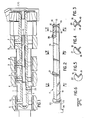
- FIG. 1 An embodiment of the device for distributing lubricating oil for crazy elements on a shaft, according to the invention, is shown in FIG. 1.
- the shaft 1 is a secondary shaft of a gearbox of a passenger motor vehicle. It carries four idler gears: a mad element 2 for the first gear, an idler element 3 for the second gear, an idler element 4 for the third gear and an idler element 5 for the fourth gear.
- the shaft 1 has a central feed channel 6, one end of which 26 is connected to the source of lubricating oil and the other end of which is closed.
- the central feed channel 6 is connected to n radial feed holes for each of the lubrication points.
- n radial feed holes for each of the lubrication points.
- An oil distribution element 11 is engaged in the central channel 6, and it is secured to the shaft 1 by means of an immobilization system.
- the oil distribution element 11 has n elementary channels (12, 13, 14, 15) corresponding to the n radial supply holes (7, 8, 9, 10).
- the oil distribution element 11 consists of n fins (16, 17, 18, 19) and n-1 radial elements (20, 21, 22).
- Each elementary channel (12, 13, 14, 15) is the combination of two fins, and it is closed in the area of the radial point of supply (7, 8, 9, 10) desired by means of the corresponding radial element (20, 21, 22) which is located after said radial supply hole (7, 8, 9, 10).
- the distribution element is constituted by four fins (16, 17, 18, 19) arranged at 90 degrees from each other, and by three radial elements (20, 21, 22) so as to cooperate with the four radial holes d 'food (7, 8, 9, 10).
- the first elementary channel (12) is characterized by the first fin (16) and the second fin (17) and by the first radial element (20).
- the second elementary channel (13) is constituted by the second fin (17) and the third fin (18) up to the first radial element (20), then by the first fin (16) and the third fin (18) which are opposite to the second radial element (21).
- the third elementary channel (14) is constituted by the third fin (18) and the fourth fin (19) to the second radial element (21) then by the fourth fin (19) and the first fin (16) to third radial element (22).
- the fourth elementary channel (15) consists of the fourth fin (19) and the first fin (16) up to the third radial element (22).
- the fins 16, 17, 18 and 19 are distributed so as to obtain unequal angular sectors in order to have different lubrication rates.
- the immobilization system of the oil distribution element 11 consists of a flexible axial bar 23, which is provided at the end with a stud 24.
- the axial bar 23 is integral with the last radial element 22 of the element oil distribution 11.
- the stud 24 engages in a radial hole 25, which is arranged in the shaft 1.
- the axial bar 23 which is flexible, approaches the axis, and it returns to its initial position as soon as its stud 24 arrives opposite the radial hole 25, in which it engages.
- the radial hole 25 can have the same axis as one of the radial supply holes 7, 8, 9 or 10, for example the radial supply hole 10.
- the fins are inclined in the form of a helix along the axis of the oil distribution element 11. This gives a screw which sucks the lubricating oil when rotating the shaft 1.
Landscapes
- Engineering & Computer Science (AREA)
- General Engineering & Computer Science (AREA)
- Mechanical Engineering (AREA)
- General Details Of Gearings (AREA)
Applications Claiming Priority (2)
| Application Number | Priority Date | Filing Date | Title |
|---|---|---|---|
| FR8812578A FR2637038B1 (fr) | 1988-09-27 | 1988-09-27 | Dispositif de repartition d'huile de lubrification d'elements fous sur un arbre |
| FR8812578 | 1988-09-27 |
Publications (1)
| Publication Number | Publication Date |
|---|---|
| EP0362043A1 true EP0362043A1 (de) | 1990-04-04 |
Family
ID=9370416
Family Applications (1)
| Application Number | Title | Priority Date | Filing Date |
|---|---|---|---|
| EP89402623A Withdrawn EP0362043A1 (de) | 1988-09-27 | 1989-09-26 | Schmierölverteilungsvorrichtung für frei drehbare Teile auf einer Welle |
Country Status (3)
| Country | Link |
|---|---|
| EP (1) | EP0362043A1 (de) |
| JP (1) | JPH02163556A (de) |
| FR (1) | FR2637038B1 (de) |
Cited By (14)
| Publication number | Priority date | Publication date | Assignee | Title |
|---|---|---|---|---|
| DE4117409A1 (de) * | 1991-05-28 | 1992-12-03 | Audi Ag | Schmiervorrichtung |
| WO2001007762A1 (de) * | 1999-07-22 | 2001-02-01 | Daimlerchrysler Ag | Hohlwelle mit innenkanälen, insbesondere ölkanälen |
| NL1010860C2 (nl) * | 1997-12-22 | 2004-07-19 | Luk Getriebe Systeme Gmbh | Overbrengingsmechanisme. |
| WO2005019699A1 (de) * | 2003-07-23 | 2005-03-03 | Zf Friedrichshafen Ag | Ölführende welle |
| WO2006043008A1 (fr) * | 2004-10-22 | 2006-04-27 | Renault S.A.S | Boite de vitesses pour vehicule automobile comprenant un dispositif de lubrification forcee des roues d'engrenage |
| EP1731800A1 (de) * | 2005-06-09 | 2006-12-13 | Renault s.a.s. | Getriebe mit Pumpe zur Zahnräderschmierung |
| FR2888909A1 (fr) * | 2005-07-21 | 2007-01-26 | Renault Sas | Dispositif de lubrification pour boite de vitesses |
| DE102009027534A1 (de) * | 2009-07-08 | 2011-01-13 | Zf Friedrichshafen Ag | Schmiermittelversorgungssystem, insbesondere für ein Kraftfahrzeuggetriebe |
| DE102012214770A1 (de) | 2012-08-20 | 2014-02-20 | Schaeffler Technologies AG & Co. KG | Steckwellensystem und Differenzial mit einem solchen Steckwellensystem sowie Schmierkanäle in einem Sonnenrad |
| DE102012214771A1 (de) | 2012-08-20 | 2014-02-20 | Schaeffler Technologies AG & Co. KG | Steckwellensystem, Differenzial mit Steckwellensystem, Ölführung in Wellensystemen von Getrieben und Stahl-Ölfangschale für die Ölung einer Welle |
| DE102013203762A1 (de) | 2013-03-06 | 2014-09-11 | Schaeffler Technologies Gmbh & Co. Kg | Steckwellensystem, Differenzial mit Steckwellensystem, Ölführung in Wellensystemen von Getrieben und Stahl-Ölfangschale für die Ölung einer Welle |
| DE102008056249B4 (de) * | 2007-11-09 | 2015-07-02 | GM Global Technology Operations LLC (n. d. Ges. d. Staates Delaware) | Fluidübertragungseinsatz |
| DE102014215406A1 (de) | 2014-08-05 | 2016-02-11 | Zf Friedrichshafen Ag | Verfahren zur Herstellung einer Getriebewelle, umfassend zumindest einen axial verlaufenden Ölkanal |
| CN106838330A (zh) * | 2017-04-19 | 2017-06-13 | 中煤科工集团重庆研究院有限公司 | 旋转密封配油器 |
Families Citing this family (1)
| Publication number | Priority date | Publication date | Assignee | Title |
|---|---|---|---|---|
| EP2875262B1 (de) | 2012-07-19 | 2019-09-04 | Koyo Bearings North America LLC | Stecker für eine planetenbolzenanordnung |
Citations (5)
| Publication number | Priority date | Publication date | Assignee | Title |
|---|---|---|---|---|
| DE83368C (de) * | ||||
| DE1009446B (de) * | 1954-06-14 | 1957-05-29 | Eisen & Stahlind Ag | Einfuehrung mehrerer unabhaengiger Schmier- oder Druckmittelleitungen in eine umlaufende Welle von einem freien Wellenende aus |
| FR1357513A (fr) * | 1963-05-29 | 1964-04-03 | Dispositif pour la lubrification | |
| FR2328879A1 (fr) * | 1975-10-20 | 1977-05-20 | Voest Ag | Rouleau, en particulier rouleau de guidage de barre dans une installation de coulee continue, a plusieurs canaux de graissage internes alimentes selectivement |
| GB2156485A (en) * | 1983-09-28 | 1985-10-09 | Nippon Piston Ring Co Ltd | Cam shaft with lubricating oil supply function |
-
1988
- 1988-09-27 FR FR8812578A patent/FR2637038B1/fr not_active Expired - Lifetime
-
1989
- 1989-09-26 EP EP89402623A patent/EP0362043A1/de not_active Withdrawn
- 1989-09-27 JP JP24935789A patent/JPH02163556A/ja active Pending
Patent Citations (5)
| Publication number | Priority date | Publication date | Assignee | Title |
|---|---|---|---|---|
| DE83368C (de) * | ||||
| DE1009446B (de) * | 1954-06-14 | 1957-05-29 | Eisen & Stahlind Ag | Einfuehrung mehrerer unabhaengiger Schmier- oder Druckmittelleitungen in eine umlaufende Welle von einem freien Wellenende aus |
| FR1357513A (fr) * | 1963-05-29 | 1964-04-03 | Dispositif pour la lubrification | |
| FR2328879A1 (fr) * | 1975-10-20 | 1977-05-20 | Voest Ag | Rouleau, en particulier rouleau de guidage de barre dans une installation de coulee continue, a plusieurs canaux de graissage internes alimentes selectivement |
| GB2156485A (en) * | 1983-09-28 | 1985-10-09 | Nippon Piston Ring Co Ltd | Cam shaft with lubricating oil supply function |
Cited By (22)
| Publication number | Priority date | Publication date | Assignee | Title |
|---|---|---|---|---|
| DE4117409A1 (de) * | 1991-05-28 | 1992-12-03 | Audi Ag | Schmiervorrichtung |
| NL1010860C2 (nl) * | 1997-12-22 | 2004-07-19 | Luk Getriebe Systeme Gmbh | Overbrengingsmechanisme. |
| WO2001007762A1 (de) * | 1999-07-22 | 2001-02-01 | Daimlerchrysler Ag | Hohlwelle mit innenkanälen, insbesondere ölkanälen |
| WO2005019699A1 (de) * | 2003-07-23 | 2005-03-03 | Zf Friedrichshafen Ag | Ölführende welle |
| WO2006043008A1 (fr) * | 2004-10-22 | 2006-04-27 | Renault S.A.S | Boite de vitesses pour vehicule automobile comprenant un dispositif de lubrification forcee des roues d'engrenage |
| FR2877065A1 (fr) * | 2004-10-22 | 2006-04-28 | Renault Sas | Boite de vitesses pour vehicule automobile comprenant un dispositif de lubrification forcee des roues d'engrenage |
| EP1731800A1 (de) * | 2005-06-09 | 2006-12-13 | Renault s.a.s. | Getriebe mit Pumpe zur Zahnräderschmierung |
| FR2887003A1 (fr) * | 2005-06-09 | 2006-12-15 | Renault Sas | Boite de vitesses avec pompe de lubrification des pignons |
| FR2888909A1 (fr) * | 2005-07-21 | 2007-01-26 | Renault Sas | Dispositif de lubrification pour boite de vitesses |
| WO2007010152A3 (fr) * | 2005-07-21 | 2007-03-08 | Renault Sa | Dispositif de lubrification pour boite de vitesses |
| DE102008056249B4 (de) * | 2007-11-09 | 2015-07-02 | GM Global Technology Operations LLC (n. d. Ges. d. Staates Delaware) | Fluidübertragungseinsatz |
| DE102009027534A1 (de) * | 2009-07-08 | 2011-01-13 | Zf Friedrichshafen Ag | Schmiermittelversorgungssystem, insbesondere für ein Kraftfahrzeuggetriebe |
| DE102012214770A1 (de) | 2012-08-20 | 2014-02-20 | Schaeffler Technologies AG & Co. KG | Steckwellensystem und Differenzial mit einem solchen Steckwellensystem sowie Schmierkanäle in einem Sonnenrad |
| DE102012214771A1 (de) | 2012-08-20 | 2014-02-20 | Schaeffler Technologies AG & Co. KG | Steckwellensystem, Differenzial mit Steckwellensystem, Ölführung in Wellensystemen von Getrieben und Stahl-Ölfangschale für die Ölung einer Welle |
| WO2014029513A1 (de) | 2012-08-20 | 2014-02-27 | Schaeffler Technologies AG & Co. KG | Steckwellensystem, differenzial mit steckwellensystem, ölführung in wellensystemen von getrieben und stahl-ölfangschale für die ölung einer welle |
| US9322467B2 (en) | 2012-08-20 | 2016-04-26 | Schaeffler Technologies AG & Co. KG | Insert shaft system, differential with insert shaft system, oil distribution in shaft systems of transmissions, and steel oil drip pan for the oiling of a shaft |
| DE102012214771B4 (de) * | 2012-08-20 | 2019-11-21 | Schaeffler Technologies AG & Co. KG | Steckwellensystem und Differenzial mit Steckwellensystem |
| DE102012214770B4 (de) | 2012-08-20 | 2022-02-17 | Schaeffler Technologies AG & Co. KG | Steckwellensystem und Differenzial mit einem solchen Steckwellensystem sowie Schmierkanäle in einem Sonnenrad |
| DE102013203762A1 (de) | 2013-03-06 | 2014-09-11 | Schaeffler Technologies Gmbh & Co. Kg | Steckwellensystem, Differenzial mit Steckwellensystem, Ölführung in Wellensystemen von Getrieben und Stahl-Ölfangschale für die Ölung einer Welle |
| DE102014215406A1 (de) | 2014-08-05 | 2016-02-11 | Zf Friedrichshafen Ag | Verfahren zur Herstellung einer Getriebewelle, umfassend zumindest einen axial verlaufenden Ölkanal |
| CN106838330A (zh) * | 2017-04-19 | 2017-06-13 | 中煤科工集团重庆研究院有限公司 | 旋转密封配油器 |
| CN106838330B (zh) * | 2017-04-19 | 2019-07-05 | 中煤科工集团重庆研究院有限公司 | 旋转密封配油器 |
Also Published As
| Publication number | Publication date |
|---|---|
| FR2637038B1 (fr) | 1990-11-09 |
| JPH02163556A (ja) | 1990-06-22 |
| FR2637038A1 (fr) | 1990-03-30 |
Similar Documents
| Publication | Publication Date | Title |
|---|---|---|
| EP0362043A1 (de) | Schmierölverteilungsvorrichtung für frei drehbare Teile auf einer Welle | |
| EP0224407B1 (de) | Zahnradgetriebe mit einer Antriebswelle und zwei Vorgelegewellen | |
| FR2470305A1 (fr) | Tendeur de courroie | |
| FR2539831A1 (fr) | Mecanisme d'embrayage ou de freinage a disque equipe d'un moyen de coincement a action elastique inserable radialement entre un disque et le porte-disques associe | |
| EP1072826B1 (de) | Schaltgabel für Getriebe eines Kraftfahrzeuges | |
| EP0448457A1 (de) | Vorrichtung aus zwei synchronisierten, zusätzlichen Gängen für ein Stufengetriebe | |
| GB1582796A (en) | Multi-speed hub for a bicycle | |
| FR2510670A1 (fr) | Moteur hydraulique a barillet | |
| FR2853613A1 (fr) | Systeme de transmission pour entrainements de directions de vehicules automobiles | |
| KR20200061096A (ko) | 변속기 내장형 크랭크 조립체 | |
| EP1234743A1 (de) | Lenksäule mit feststehendem Nabenkissen und entsprechendes Kraftfahrzeug | |
| EP0737827B1 (de) | In Getriebe eingebaute Steuerung mit einer Federeinrichtung der Wählorgane | |
| FR2803954A1 (fr) | Motoreducteur destine a des equipements fonctionnels de vehicules, pourvu d'une bague magnetique de mesure de la vitesse de rotation de son arbre d'induit | |
| FR2717554A1 (fr) | Ensemble pour déterminer l'écartement d'organes de fixation de câblages électriques. | |
| EP0081024A1 (de) | Einrichtung zum wahlweisen Antrieb von Maschinen oder Vorrichtungen durch die Zapfwelle eines landwirtschaftlichen Schleppers | |
| EP2726761A1 (de) | Planetenträgersystem für umlaufgetriebe | |
| FR2730974A1 (fr) | Dispositif d'entrainement | |
| FR2614382A1 (fr) | Poulie pour l'entrainement de machine tournante | |
| FR3136024B1 (fr) | Dispositif de couplage pour réducteur à deux rapports de vitesses | |
| EP0094857B1 (de) | Sensorvorrichtung, insbesondere zum Antrieb eines Fahrradtachometers | |
| EP0219411A1 (de) | Getriebemotor für den gleichzeitigen Antrieb zweier Organe | |
| EP0422976A1 (de) | Elastische Rückstellvorrichtung, insbesondere für einen Schaltfinger eines Kraftfahrzeuggetriebes | |
| FR2768793A1 (fr) | Dispositif de tension pour les transmissions de mouvements de rotation par courroies, chaines ou cables | |
| FR2585012A1 (fr) | Dispositif de treuillage de vehicules | |
| FR2553043A1 (fr) | Boite de vitesses a surmultiplicateur |
Legal Events
| Date | Code | Title | Description |
|---|---|---|---|
| PUAI | Public reference made under article 153(3) epc to a published international application that has entered the european phase |
Free format text: ORIGINAL CODE: 0009012 |
|
| 17P | Request for examination filed |
Effective date: 19890929 |
|
| AK | Designated contracting states |
Kind code of ref document: A1 Designated state(s): DE ES GB IT |
|
| 17Q | First examination report despatched |
Effective date: 19910710 |
|
| STAA | Information on the status of an ep patent application or granted ep patent |
Free format text: STATUS: THE APPLICATION IS DEEMED TO BE WITHDRAWN |
|
| 18D | Application deemed to be withdrawn |
Effective date: 19930401 |