EP0362052B1 - Düsenkonstruktion für einen Kombinationsantrieb (Turbo-Staustrahl-Rakete) - Google Patents
Düsenkonstruktion für einen Kombinationsantrieb (Turbo-Staustrahl-Rakete) Download PDFInfo
- Publication number
- EP0362052B1 EP0362052B1 EP19890402637 EP89402637A EP0362052B1 EP 0362052 B1 EP0362052 B1 EP 0362052B1 EP 19890402637 EP19890402637 EP 19890402637 EP 89402637 A EP89402637 A EP 89402637A EP 0362052 B1 EP0362052 B1 EP 0362052B1
- Authority
- EP
- European Patent Office
- Prior art keywords
- nozzle
- propulsion unit
- divergent
- section
- jack
- Prior art date
- Legal status (The legal status is an assumption and is not a legal conclusion. Google has not performed a legal analysis and makes no representation as to the accuracy of the status listed.)
- Expired - Lifetime
Links
- 239000007789 gas Substances 0.000 claims description 27
- 238000002347 injection Methods 0.000 claims description 13
- 239000007924 injection Substances 0.000 claims description 13
- 238000002485 combustion reaction Methods 0.000 claims description 10
- 238000011144 upstream manufacturing Methods 0.000 claims description 8
- 230000007704 transition Effects 0.000 claims description 3
- 238000007599 discharging Methods 0.000 claims 2
- 230000001141 propulsive effect Effects 0.000 claims 1
- 239000003380 propellant Substances 0.000 description 32
- 239000001257 hydrogen Substances 0.000 description 18
- 229910052739 hydrogen Inorganic materials 0.000 description 18
- UFHFLCQGNIYNRP-UHFFFAOYSA-N Hydrogen Chemical compound [H][H] UFHFLCQGNIYNRP-UHFFFAOYSA-N 0.000 description 15
- 210000003462 vein Anatomy 0.000 description 10
- QVGXLLKOCUKJST-UHFFFAOYSA-N atomic oxygen Chemical compound [O] QVGXLLKOCUKJST-UHFFFAOYSA-N 0.000 description 3
- 239000001301 oxygen Substances 0.000 description 3
- 229910052760 oxygen Inorganic materials 0.000 description 3
- 230000002441 reversible effect Effects 0.000 description 3
- 230000001133 acceleration Effects 0.000 description 2
- 230000015572 biosynthetic process Effects 0.000 description 2
- 239000000446 fuel Substances 0.000 description 2
- 150000002431 hydrogen Chemical class 0.000 description 2
- 239000007788 liquid Substances 0.000 description 2
- 230000001172 regenerating effect Effects 0.000 description 2
- MYMOFIZGZYHOMD-UHFFFAOYSA-N Dioxygen Chemical compound O=O MYMOFIZGZYHOMD-UHFFFAOYSA-N 0.000 description 1
- 230000006978 adaptation Effects 0.000 description 1
- 230000000712 assembly Effects 0.000 description 1
- 238000000429 assembly Methods 0.000 description 1
- 239000000567 combustion gas Substances 0.000 description 1
- 230000006835 compression Effects 0.000 description 1
- 238000007906 compression Methods 0.000 description 1
- 230000001143 conditioned effect Effects 0.000 description 1
- 238000001816 cooling Methods 0.000 description 1
- 238000010586 diagram Methods 0.000 description 1
- 125000004435 hydrogen atom Chemical group [H]* 0.000 description 1
- 239000000843 powder Substances 0.000 description 1
- 238000005096 rolling process Methods 0.000 description 1
- 239000000243 solution Substances 0.000 description 1
- 239000007858 starting material Substances 0.000 description 1
Images

Classifications
-
- F—MECHANICAL ENGINEERING; LIGHTING; HEATING; WEAPONS; BLASTING
- F02—COMBUSTION ENGINES; HOT-GAS OR COMBUSTION-PRODUCT ENGINE PLANTS
- F02K—JET-PROPULSION PLANTS
- F02K7/00—Plants in which the working fluid is used in a jet only, i.e. the plants not having a turbine or other engine driving a compressor or a ducted fan; Control thereof
- F02K7/10—Plants in which the working fluid is used in a jet only, i.e. the plants not having a turbine or other engine driving a compressor or a ducted fan; Control thereof characterised by having ram-action compression, i.e. aero-thermo-dynamic-ducts or ram-jet engines
- F02K7/18—Composite ram-jet/rocket engines
-
- F—MECHANICAL ENGINEERING; LIGHTING; HEATING; WEAPONS; BLASTING
- F02—COMBUSTION ENGINES; HOT-GAS OR COMBUSTION-PRODUCT ENGINE PLANTS
- F02K—JET-PROPULSION PLANTS
- F02K7/00—Plants in which the working fluid is used in a jet only, i.e. the plants not having a turbine or other engine driving a compressor or a ducted fan; Control thereof
- F02K7/10—Plants in which the working fluid is used in a jet only, i.e. the plants not having a turbine or other engine driving a compressor or a ducted fan; Control thereof characterised by having ram-action compression, i.e. aero-thermo-dynamic-ducts or ram-jet engines
- F02K7/16—Composite ram-jet/turbo-jet engines
-
- F—MECHANICAL ENGINEERING; LIGHTING; HEATING; WEAPONS; BLASTING
- F02—COMBUSTION ENGINES; HOT-GAS OR COMBUSTION-PRODUCT ENGINE PLANTS
- F02K—JET-PROPULSION PLANTS
- F02K9/00—Rocket-engine plants, i.e. plants carrying both fuel and oxidant therefor; Control thereof
- F02K9/74—Rocket-engine plants, i.e. plants carrying both fuel and oxidant therefor; Control thereof combined with another jet-propulsion plant
- F02K9/78—Rocket-engine plants, i.e. plants carrying both fuel and oxidant therefor; Control thereof combined with another jet-propulsion plant with an air-breathing jet-propulsion plant
Definitions
- the present invention relates to a nozzle structure for a combined turbo-stato-rocket propellant whose annular gas ejection stream in turbojet and ramjet modes, surrounds an axial rocket engine and opens into the ejection nozzle of said engine -rocket.
- thrusters The purpose of such thrusters is to push an aircraft from takeoff to hypersonic speeds by giving it the best performance at all times of the flight, that is to say by achieving the best compromise between thrust / mass, thrust / frontal area, large specific impulse.
- a propellant was used using liquid hydrogen and liquid oxygen for fuels and using three operating modes.
- the thruster From start-up and up to a Mach number of 5 and 6, from altitude 0 to around 20 km, the thruster operates in turbo expander or turbo rocket mode (in the case of a gas generator thruster) the exhaust gases from the turbine, rich in hydrogen being injected into the air stream, previously compressed by the compressor, to be burned and ejected in a convergent-divergent nozzle.
- turbo expander or turbo rocket mode in the case of a gas generator thruster
- the propellant operates in ramjet mode, the air entering the vein then not being compressed apart from simple dynamic compression in the inlet of air, the compressor put into autorotation with a pressure ratio close to unity.
- the fuel injected into the vein is on the one hand hydrogen coming directly from the regenerative circuit (heat exchanger on the wall of the nozzle), on the other hand hydrogen coming from this same circuit which was then expanded in the LH2 turbopump turbine of the hydraulic circuit.
- the gases injected into the combustion chamber of the ramjet consist of hydrogen directly from the regenerative circuit and by the combustion gases of the gas generator, after partial use of the energy of these gases for driving the turbopumps at LH2 and LOx.
- the propellant switches to rocket mode where the combustion chamber placed in the annular vein is no longer supplied and where all of the propulsion gases from the airplane come from a rocket engine arranged axially.
- a good solution consists in making a propellant whose propellant turbine is disposed inside a central body which is surrounded by an annular vein comprising an air intake sleeve , the compressor driven by the aforementioned turbine and a combustion chamber for the turbo and stato operating modes.
- the combustion chamber ejection gases propel the aircraft in these two operating modes by being ejected into a convergent-divergent nozzle.
- the object of the present invention is to produce a nozzle structure such that the downstream divergent part of the convergent-divergent nozzle of the turbo and stato modes is common with the downstream part of the nozzle of the rocket engine, in order to reduce the axial bulk. and radial of the thruster.
- the invention also aims to achieve a nozzle structure of the aforementioned kind which is reversible since the advantage of planes or shuttles powered by such thrusters, is to be able to return to the ground by its own means and using its propulsion modes stato and turbo when returning from missions it performs outside the Earth's atmosphere.
- FR-A-2434273 and FR-A-2568316 already disclose deployable nozzles for rocket engines, the disadvantage of which is either irreversibility or bulk.
- the invention also aims to provide a device in which the neck section of the converging-diverging nozzle for the turbo and stato modes is adjustable so as to be adjustable as best as possible to the propulsion conditions specific to each of the turbo and stato modes.
- the subject of the invention is therefore a combined turbo-stato-rocket propellant as described above and in which the propellant nozzle has a first fixed diverging section located just downstream of the rocket engine, a second diverging section being able to be retracted and replaced by movable means forming with the external casing a convergent-divergent neck with variable section for the gases coming from the annular vein in turbo or stato mode, the second section being followed by a third fixed diverging section forming diverging nozzle for the three turbo, stato and rocket propulsion modes.
- the mobile means forming the convergent-divergent neck are constituted by a first cylindrical shell, movable axially downstream and downstream of which are movable flaps.
- the first cylindrical shell is movable in axial translation by means of at least a first screw jack on the rod of which it is fixed, said jack being parallel to the axis of the propellant and having its stem oriented downstream.
- a second cylinder has its body integral with the head of the first cylinder and the first cylindrical shell. It is arranged parallel to the longitudinal axis of the propellant and oriented downstream and its rod can cause in axial translation a movable intermediate structure downstream of which is fixed the second retractable divergent section of the nozzle.
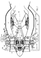
- FIG. 1 has been shown a combined turbo-stato-rocket propellant according to the objectives of the present invention and which includes improvements.
- the external environment of the propellant (supply circuits) has been shown for an "expander” supply cycle corresponding to FIG. 2 for purposes of exemplification.
- Adaptation to a "gas generator” circuit does not modify the internal structure of the propellant, only the power supplies being modified.
- the propellant comprises an annular stream 1 formed between a central body 2 and an external casing 3. Upstream of the stream is arranged an air compressor 4 here formed of two counter-rotating stages 4a, 4b connected by concentric shafts 5a, 5b to two counter-rotating and nested rotors 6a, 6b, of a power turbine 6, arranged inside the central body downstream of the compressor 4.
- an air compressor 4 here formed of two counter-rotating stages 4a, 4b connected by concentric shafts 5a, 5b to two counter-rotating and nested rotors 6a, 6b, of a power turbine 6, arranged inside the central body downstream of the compressor 4.
- a rocket motor 9 In the downstream part of the body is arranged a rocket motor 9, the propellant gases of which are ejected into a nozzle 10 formed by a first divergent section 10a, a second removable section 10b and a third fixed divergent section 10c.
- the annular stream 1 used for the turbo and stato propulsion modes opens into the nozzle 10 at the location occupied in rocket mode by the removable section 10b.
- a device 11 for retracting the section 10b of the diverging portion of the rocket engine 9, and for installing a means for varying the section of the nozzle neck is disposed inside the central body 2. It allows, after retraction section 10b to set up in the vein of flaps 12 in the shape of a petal whose axial position will allow to continuously vary the section of the neck of the converging convergent nozzle in both turbo and stato modes of operation.
- the power turbine 6 is supplied with pressurized gas from an external supply circuit (which will be detailed below with reference to FIG. 2), the turbine gases reaching the upstream part of the turbine by means of an intake manifold 7 passing through structural arms 8 which connect and hold the central body 2 to the external casing 3.
- the gases which have passed through it are admitted into the combustion chamber of the stream 1 by means of an injection device 13 so as to be mixed there with the air coming from the compressor 4 and burned in injection device outlet.
- This consists of radial arms 14 regularly distributed in the vein.
- FIG 2 there is shown schematically a combined turbo-stato-rocket propellant known as an expander.
- the only propellant used in stato or turbo mode is hydrogen.
- the liquid hydrogen coming from a storage tank 101 is pumped by means of a turbopump 102 then is brought by a pipe 103 and two valves 104, 105 on the one hand to a heat exchanger 106 placed on the wall of the combustion and on the other hand to a pipe 107 which, provided with a non-return valve 108 will supply the turbines of two turbopumps, one 102 already mentioned and the other 109 intended for the oxygen supply of the engine- rocket 9.
- a valve 110 makes it possible to isolate the turbopump 109 from the circuit when necessary, that is to say in turbo and stato modes.
- the hydrogen which has just been expanded and which has therefore used part of its energy is separated into two circuits, one of which, 111, controlled by a valve 112 authorizes the injection of hydrogen into the cavity 14f of the radial arms and 19b, 20b of the rings of the injection device 13, and the other 113 of which branches out into two parts 114 and 7 each controlled by a valve 115, 116.
- the circuit 7 supplies the power turbine 6 while circuit 114 will supply the rocket engine in rocket mode 9.
- the turbine outlet 6 is connected to the internal part of the injection device 13 through the ferrule 15.
- the hydrogen at the outlet of said exchanger where it has taken calories and increased its enthalpy, is used to supply two circuits, one 117 controlled by a valve 118 allows the injection in stato mode of the hydrogen into the cavities 14f radial arms, and 19b, 20b of the collecting rings of the injection device 13, while the other circuit 119 will join the tube 107 downstream of the non-return valve 108 to provide the energy necessary for driving the 102 turbopump in turbo and stato modes.
- the turbopumps 102 and 109 are driven by the hydrogen circulating in the pipe 107 which has taken up calories in a heat exchanger 90 located on the wall of the rocket chamber 9.
- the propellant supply circuit includes an oxygen tank 120 which can be isolated by a valve 121 and whose outlet 122 is connected to the pump of the turbopump 109 whose flow rate output feeds via a tube 123 in rocket mode only, the rocket motor 9.
- the different operating modes are conditioned by the opening / closing of the different valves mentioned above in order to supply or interrupt this or that other part of the circuit, which can be summarized by the following table in which the different modes are indicated with the opening (0) / closing (F) state of each valve opposite:
- the transition to ramjet mode is carried out by isolating the turbine 6 by closing the valve 116 and simultaneously opening the valve 112 so that the hydrogen leaving the turbine of the turbopump 102 is injected by means of the pipe 111 , arms 14 and collector rings.
- the valves 104, 118 being open, the part of the hydrogen flow leaving the exchanger 106, which is not used in the turbopump 102, is injected directly by means of the pipe 117 into the arms 14 of the injection device 13.
- the entire hydrogen injection in stato mode is therefore provided from the external edge of the vein by the injection arms 14.
- the transition to rocket mode is carried out by closing the valve 104 and simultaneously opening the valves 105, 110, 115 and 121.
- the hydrogen coming from the pump 102 feeds by 107 the turbines of the two turbopumps 102 and 109, then by 113 and 114 is injected into the chamber of the rocket engine 9.
- the oxygen pumped by 109 is brought via line 123 to the chamber of the rocket engine 9.
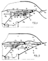
- the mobile means generally referenced 11 in FIG. 1 will be described in more detail with reference to FIGS. 3 to 5 .
- Each assembly 11 comprises a first screw jack 17 arranged longitudinally, the body 17a of which is fixed to the upstream part of the rail 16 and the rod 17b, oriented downstream is secured to a movable cylindrical shell 18 capable of sliding in axial translation under the shell 2a against which it is arranged.
- movable flaps 12 in the form of petals having a double curvature first turned towards the axis of the propellant in the upstream part of the flaps then turned radially towards the outside of the propellant in the downstream part of the flaps.
- the assembly formed by the cylindrical shell 18 and the flaps 12, movable in axial translation by means of the jack 17, constitutes, with the converging downstream part 3a of the external casing 3 which is connected to the divergent section 10c of the nozzle, the means formation of the convergent-divergent neck and variation of the section of this said neck.
- a second screw jack 22 the body 22a of which is integral with a connecting piece 23 between the rod 17b of the first jack 17 and the ferrule 18, is arranged parallel to the longitudinal axis of the propellant with its rod 22b oriented towards the 'downstream.
- an intermediate structure 24 movable in axial translation and having rollers 25 for rolling on the fixed rail 16.
- On the downstream part of the movable structure 24 is welded a conical ferrule forming the second divergent section 10b of the nozzle 10, and it is on a yoke 26 of this ferrule 10b that the rod 22b of the second cylinder 22 is articulated.
- the mobile structure 24 comprises two longitudinal guide rails 27, with which the rollers 28 cooperate carried by a link 29 articulated on the connecting axis 21 between the ferrule 18 and the flaps 12, to allow the sliding of the rollers 28 in the rails 27.
- the flaps retract outward to allow free passage to the conical shell 10b ( Figure 5).
- the jack 17 is then gradually deployed during acceleration in turbo mode then in stato mode.
- the first cylinder 17 is in the fully extended position and the second 22 retracted, the first movable cylindrical shell 18 being in the downstream position and the flaps 12 in the downstream position in which they define a section S2 minimum nozzle throat for ejecting gas from the ramjet.
- the invention can also be applied without limitation to a propellant whose architecture of the compressor and of the turbine would be different from that shown here.
- the invention therefore applies equally to any type of propellant successively using the three modes turbo, stato and rocket propellant and whose ejection stream in turbo and stato modes is annular and surrounds the rocket engine.
Landscapes
- Engineering & Computer Science (AREA)
- Chemical & Material Sciences (AREA)
- Combustion & Propulsion (AREA)
- Mechanical Engineering (AREA)
- General Engineering & Computer Science (AREA)
- Jet Pumps And Other Pumps (AREA)
- Supercharger (AREA)
- Aerodynamic Tests, Hydrodynamic Tests, Wind Tunnels, And Water Tanks (AREA)
Claims (11)
Applications Claiming Priority (2)
| Application Number | Priority Date | Filing Date | Title |
|---|---|---|---|
| FR8812646A FR2637017B1 (fr) | 1988-09-28 | 1988-09-28 | Structure de tuyere pour propulseur combine turbo-stato-fusee |
| FR8812646 | 1988-09-28 |
Publications (2)
| Publication Number | Publication Date |
|---|---|
| EP0362052A1 EP0362052A1 (de) | 1990-04-04 |
| EP0362052B1 true EP0362052B1 (de) | 1991-10-30 |
Family
ID=9370467
Family Applications (1)
| Application Number | Title | Priority Date | Filing Date |
|---|---|---|---|
| EP19890402637 Expired - Lifetime EP0362052B1 (de) | 1988-09-28 | 1989-09-27 | Düsenkonstruktion für einen Kombinationsantrieb (Turbo-Staustrahl-Rakete) |
Country Status (4)
| Country | Link |
|---|---|
| EP (1) | EP0362052B1 (de) |
| JP (1) | JPH0672573B2 (de) |
| DE (1) | DE68900386D1 (de) |
| FR (1) | FR2637017B1 (de) |
Cited By (7)
| Publication number | Priority date | Publication date | Assignee | Title |
|---|---|---|---|---|
| WO2001094197A1 (en) * | 2000-06-07 | 2001-12-13 | Pursuit Dynamics Plc | Propulsion system |
| US6662549B2 (en) | 2000-06-07 | 2003-12-16 | Pursuit Dynamics Plc | Propulsion system |
| US8193395B2 (en) | 2007-05-02 | 2012-06-05 | Pursuit Dynamics Plc | Biomass treatment process and system |
| US8419378B2 (en) | 2004-07-29 | 2013-04-16 | Pursuit Dynamics Plc | Jet pump |
| US8789769B2 (en) | 2006-09-15 | 2014-07-29 | Tyco Fire & Security Gmbh | Mist generating apparatus and method |
| US9004375B2 (en) | 2004-02-26 | 2015-04-14 | Tyco Fire & Security Gmbh | Method and apparatus for generating a mist |
| US9010663B2 (en) | 2004-02-26 | 2015-04-21 | Tyco Fire & Security Gmbh | Method and apparatus for generating a mist |
Families Citing this family (7)
| Publication number | Priority date | Publication date | Assignee | Title |
|---|---|---|---|---|
| JP2707822B2 (ja) * | 1990-10-05 | 1998-02-04 | 日産自動車株式会社 | ラムロケット |
| US20080103217A1 (en) | 2006-10-31 | 2008-05-01 | Hari Babu Sunkara | Polyether ester elastomer composition |
| CN102826227B (zh) * | 2012-08-22 | 2015-09-09 | 冯加伟 | 无人空天战机 |
| CN103993982A (zh) * | 2014-04-25 | 2014-08-20 | 西北工业大学 | 可实现多方向推力矢量控制的双s弯红外隐身喷管结构 |
| KR102940704B1 (ko) | 2020-05-05 | 2026-03-18 | 아틀란티스 리서치 랩스 인크. | 멀티 모드 추진 시스템 |
| EP3985241B1 (de) * | 2020-10-14 | 2023-11-29 | Taiwan Innovative Space, Inc. | Motor- und brennstoffbetriebenes hybridsystem für raketentriebwerk |
| CN119412245B (zh) * | 2024-11-14 | 2025-09-05 | 西北工业大学 | 宽域火箭基冲压发动机与斜爆震发动机流道耦合的一体化流道 |
Family Cites Families (7)
| Publication number | Priority date | Publication date | Assignee | Title |
|---|---|---|---|---|
| US2933886A (en) * | 1953-04-15 | 1960-04-26 | Sharma Devendra Nath | Turbojet engine convertible to ramjet engine |
| NL262125A (de) * | 1960-04-01 | |||
| US3192712A (en) * | 1962-12-31 | 1965-07-06 | Gen Electric | Load balancing arrangement for annular variable area jet exhaust nozzle |
| US3374631A (en) * | 1965-08-16 | 1968-03-26 | Mcdonnell Aircraft Corp | Combination subsonic and supersonic propulsion system and apparatus |
| US4213566A (en) * | 1978-08-25 | 1980-07-22 | Hercules Incorporated | Nested cone extendible nozzle system for a rocket motor |
| DE3427169C2 (de) * | 1984-07-24 | 1987-04-30 | Messerschmitt-Bölkow-Blohm GmbH, 8012 Ottobrunn | Raketentriebwerk für Raumflüge |
| DE3738703A1 (de) * | 1987-05-27 | 1988-12-08 | Mtu Muenchen Gmbh | Kombiniertes, umschaltbares strahltriebwerk zum antrieb von flugzeugen und raumfahrzeugen |
-
1988
- 1988-09-28 FR FR8812646A patent/FR2637017B1/fr not_active Expired - Lifetime
-
1989
- 1989-09-26 JP JP25036789A patent/JPH0672573B2/ja not_active Expired - Fee Related
- 1989-09-27 EP EP19890402637 patent/EP0362052B1/de not_active Expired - Lifetime
- 1989-09-27 DE DE8989402637T patent/DE68900386D1/de not_active Expired - Lifetime
Cited By (10)
| Publication number | Priority date | Publication date | Assignee | Title |
|---|---|---|---|---|
| WO2001094197A1 (en) * | 2000-06-07 | 2001-12-13 | Pursuit Dynamics Plc | Propulsion system |
| US6662549B2 (en) | 2000-06-07 | 2003-12-16 | Pursuit Dynamics Plc | Propulsion system |
| US9004375B2 (en) | 2004-02-26 | 2015-04-14 | Tyco Fire & Security Gmbh | Method and apparatus for generating a mist |
| US9010663B2 (en) | 2004-02-26 | 2015-04-21 | Tyco Fire & Security Gmbh | Method and apparatus for generating a mist |
| US8419378B2 (en) | 2004-07-29 | 2013-04-16 | Pursuit Dynamics Plc | Jet pump |
| US9239063B2 (en) | 2004-07-29 | 2016-01-19 | Pursuit Marine Drive Limited | Jet pump |
| US8789769B2 (en) | 2006-09-15 | 2014-07-29 | Tyco Fire & Security Gmbh | Mist generating apparatus and method |
| US9931648B2 (en) | 2006-09-15 | 2018-04-03 | Tyco Fire & Security Gmbh | Mist generating apparatus and method |
| US8193395B2 (en) | 2007-05-02 | 2012-06-05 | Pursuit Dynamics Plc | Biomass treatment process and system |
| US8513004B2 (en) | 2007-05-02 | 2013-08-20 | Pursuit Dynamics Plc | Biomass treatment process |
Also Published As
| Publication number | Publication date |
|---|---|
| EP0362052A1 (de) | 1990-04-04 |
| FR2637017A1 (fr) | 1990-03-30 |
| FR2637017B1 (fr) | 1990-11-30 |
| JPH02125953A (ja) | 1990-05-14 |
| JPH0672573B2 (ja) | 1994-09-14 |
| DE68900386D1 (de) | 1991-12-05 |
Similar Documents
| Publication | Publication Date | Title |
|---|---|---|
| EP2643579B1 (de) | Kombination aus einem turboluftstrahltriebwerk und staustrahltriebwerk | |
| EP0362052B1 (de) | Düsenkonstruktion für einen Kombinationsantrieb (Turbo-Staustrahl-Rakete) | |
| EP0403372B1 (de) | Turbostrahl- und Raketenkombinationstriebwerk | |
| EP0333585B1 (de) | Kombinationstriebwerk, Rakete mit luftatmendem Turbinenstrahltriebwerk | |
| US5052176A (en) | Combination turbojet-ramjet-rocket propulsion system | |
| US6668542B2 (en) | Pulse detonation bypass engine propulsion pod | |
| EP0434565B1 (de) | Anpassungsfähiges Kombinationsstrahltriebwerk für Luft- oder Raumfahrzeug | |
| FR2599428A1 (fr) | Dispositif de propulsion combine pour aeronefs, en particulier pour avions spatiaux. | |
| US2972860A (en) | Combined variable ejector and thrust reverser | |
| FR2987081A1 (fr) | Ensemble et procede propulsifs | |
| FR2561313A1 (fr) | Dispositif de modulation de poussee | |
| EP0362053B1 (de) | Konstruktion eines Kombinationsantriebs für zwei Funktionstypen | |
| FR2687433A1 (fr) | Propulseur a composants inverses, a alimentation modulee. | |
| EP0362054B1 (de) | Gaseinspritzrohre für ein Turbinenstrahl- und Raketentriebwerk | |
| FR2698409A1 (fr) | Tuyère d'éjection de turboréacteur. | |
| FR2653496A1 (fr) | Turbo-statoreacteur integre, equipant des avions pour vol sub et/ou hypersonique. | |
| US5105615A (en) | Turbojet engine with at least one axially movable arranged sliding valve | |
| EP4025781A1 (de) | Schubumkehrvorrichtung, die ein einziges stellglied zur steuerung einer beweglichen verkleidung umfasst | |
| EP4004358A1 (de) | Konvergent-divergentes klappenpaar für eine turbinen-luftstrahl-triebwerksdüse mit variabler geometrie, deren klappen jeweils einen kühlluftumlaufkanal umfassen | |
| US4529130A (en) | Turbo machine nozzle with thrust reverser | |
| EP4004359B1 (de) | Konvergent-divergentes klappenpaar für eine turbostrahltriebwerkdüse mit variabler geometrie mit durch kontaktflächen verbundenen kühlluftzirkulationskanälen | |
| WO2022096838A1 (fr) | Partie arriere de turboreacteur comprenant une tuyere dont des volets comprennent des leviers relies a un anneau de synchronisation par des biellettes | |
| FR2712962A1 (fr) | Dispositif de postcombustion comprenant un dispositif accroche-flammes perfectionné. | |
| EP4240959A1 (de) | Heckteil eines strahltriebwerks mit einer düse mit klappen mit über vor- und nachgeschaltete lagerwände beweglichen hebeln | |
| BE551416A (de) |
Legal Events
| Date | Code | Title | Description |
|---|---|---|---|
| PUAI | Public reference made under article 153(3) epc to a published international application that has entered the european phase |
Free format text: ORIGINAL CODE: 0009012 |
|
| 17P | Request for examination filed |
Effective date: 19891011 |
|
| AK | Designated contracting states |
Kind code of ref document: A1 Designated state(s): DE FR GB IT |
|
| 17Q | First examination report despatched |
Effective date: 19910408 |
|
| GRAA | (expected) grant |
Free format text: ORIGINAL CODE: 0009210 |
|
| AK | Designated contracting states |
Kind code of ref document: B1 Designated state(s): DE FR GB IT |
|
| ITF | It: translation for a ep patent filed | ||
| REF | Corresponds to: |
Ref document number: 68900386 Country of ref document: DE Date of ref document: 19911205 |
|
| GBT | Gb: translation of ep patent filed (gb section 77(6)(a)/1977) | ||
| PLBE | No opposition filed within time limit |
Free format text: ORIGINAL CODE: 0009261 |
|
| STAA | Information on the status of an ep patent application or granted ep patent |
Free format text: STATUS: NO OPPOSITION FILED WITHIN TIME LIMIT |
|
| 26N | No opposition filed | ||
| REG | Reference to a national code |
Ref country code: GB Ref legal event code: IF02 |
|
| REG | Reference to a national code |
Ref country code: FR Ref legal event code: CD Ref country code: FR Ref legal event code: TP |
|
| REG | Reference to a national code |
Ref country code: FR Ref legal event code: CD |
|
| PGFP | Annual fee paid to national office [announced via postgrant information from national office to epo] |
Ref country code: DE Payment date: 20070829 Year of fee payment: 19 |
|
| PGFP | Annual fee paid to national office [announced via postgrant information from national office to epo] |
Ref country code: GB Payment date: 20070830 Year of fee payment: 19 |
|
| PGFP | Annual fee paid to national office [announced via postgrant information from national office to epo] |
Ref country code: IT Payment date: 20070918 Year of fee payment: 19 |
|
| PGFP | Annual fee paid to national office [announced via postgrant information from national office to epo] |
Ref country code: FR Payment date: 20070820 Year of fee payment: 19 |
|
| GBPC | Gb: european patent ceased through non-payment of renewal fee |
Effective date: 20080927 |
|
| REG | Reference to a national code |
Ref country code: FR Ref legal event code: ST Effective date: 20090529 |
|
| PG25 | Lapsed in a contracting state [announced via postgrant information from national office to epo] |
Ref country code: IT Free format text: LAPSE BECAUSE OF NON-PAYMENT OF DUE FEES Effective date: 20080927 Ref country code: DE Free format text: LAPSE BECAUSE OF NON-PAYMENT OF DUE FEES Effective date: 20090401 |
|
| PG25 | Lapsed in a contracting state [announced via postgrant information from national office to epo] |
Ref country code: FR Free format text: LAPSE BECAUSE OF NON-PAYMENT OF DUE FEES Effective date: 20080930 |
|
| PG25 | Lapsed in a contracting state [announced via postgrant information from national office to epo] |
Ref country code: GB Free format text: LAPSE BECAUSE OF NON-PAYMENT OF DUE FEES Effective date: 20080927 |