EP0362068B1 - Elektrodynamisch-fluidische Wandlerausrüstung für einen pneumatischen Lautsprecher - Google Patents
Elektrodynamisch-fluidische Wandlerausrüstung für einen pneumatischen Lautsprecher Download PDFInfo
- Publication number
- EP0362068B1 EP0362068B1 EP89402667A EP89402667A EP0362068B1 EP 0362068 B1 EP0362068 B1 EP 0362068B1 EP 89402667 A EP89402667 A EP 89402667A EP 89402667 A EP89402667 A EP 89402667A EP 0362068 B1 EP0362068 B1 EP 0362068B1
- Authority
- EP
- European Patent Office
- Prior art keywords
- support
- moveable
- order
- transducer
- elastomer
- Prior art date
- Legal status (The legal status is an assumption and is not a legal conclusion. Google has not performed a legal analysis and makes no representation as to the accuracy of the status listed.)
- Expired - Lifetime
Links
Images

Classifications
-
- H—ELECTRICITY
- H04—ELECTRIC COMMUNICATION TECHNIQUE
- H04R—LOUDSPEAKERS, MICROPHONES, GRAMOPHONE PICK-UPS OR LIKE ACOUSTIC ELECTROMECHANICAL TRANSDUCERS; ELECTRIC HEARING AIDS; PUBLIC ADDRESS SYSTEMS
- H04R9/00—Transducers of moving-coil, moving-strip, or moving-wire type
- H04R9/02—Details
- H04R9/04—Construction, mounting, or centering of coil
- H04R9/045—Mounting
-
- H—ELECTRICITY
- H04—ELECTRIC COMMUNICATION TECHNIQUE
- H04R—LOUDSPEAKERS, MICROPHONES, GRAMOPHONE PICK-UPS OR LIKE ACOUSTIC ELECTROMECHANICAL TRANSDUCERS; ELECTRIC HEARING AIDS; PUBLIC ADDRESS SYSTEMS
- H04R1/00—Details of transducers, loudspeakers or microphones
- H04R1/42—Combinations of transducers with fluid-pressure or other non-electrical amplifying means
Definitions
- the invention relates to a movable assembly for the mixed electrodynamic and fluidic transducer of a pneumatic loudspeaker, comprising an axially movable tubular support, one end of which carries the voice coil in the annular air gap of the electrodynamic stage of the transducer, and whose l the other end forms a movable spout in the neck of an annular constriction of the fluid stage of the transducer, the middle part of said support being sandwiched between two concentric membranes separating the electrodynamic and fluid stages of the transducer.
- Patents FR-A-2,442,565 and 2,572,615 are known to the pneumatic loudspeaker in which the mobile assembly with an electromagnetic coil is extended by a fluid modulator constituted by a spout which moves in the passage of the flow of air. The movement, controlled by the electrodynamic transducer which receives the voice input signal, modulates the air flow and gives rise to an amplified sound signal compared to the input signal.
- the quality of reproduction of the sound signal depends, as in any loudspeaker, on the quality of the transducer, that is to say on the inertia and the rigidity of the moving equipment.
- the spout In a pneumatic loudspeaker of the type described above, the spout must be particularly rigid in order to be able to withstand the pressure of the fluid that it is supposed to control while the mobile assembly of which the modulating spout is part must have low inertia. These two qualities are antagonistic, so we have chosen, because of the efforts generated by the air flow to be controlled, to favor rigidity.
- the solution therefore consisted in the use of a thick coil support, which resulted in a relatively large air gap and for a magnet of given dimensions, less intensity of the magnetic flux passing through the transducer coil.
- the bandwidth and performance of such transducer were unsatisfactory also the invention set itself the aim of improving these characteristics.
- the result of the invention was, inter alia, to stiffen the moving element by using the other elements of the transducer and in particular the annular elastic membrane so that said membrane acts as a hoop.
- the moving element is characterized in that said support, which has a diameter of an order of magnitude greater than its height, itself of an order of magnitude greater than its thickness, is stiffened by the aforementioned membranes, each formed of a composite hoop including between the support and a concentric rigid crown, an elastomer ring adhering thereto which has an axial height of the same order of magnitude as its radial thickness, on the one hand ensuring the elastic return of the support in axial displacement and on the other hand maintain the circularity and therefore the flatness of said support.
- FIG. 1 a distinction is made on either side of a wall 1: on one side, the fluidic stage 2 and, on the other side, the electrodynamic stage of the transducer 3.
- the entire fluid stage 2 comprises a nozzle 4 extended by an acoustic horn 5, this nozzle 4 delimiting with a profiled diffuser 6, an annular duct 7 comprising a neck 8 in the plane of which is disposed an annular spout 9.
- a cylindrical collector 10 is supplied uniformly from a capacity 11 comprising orifices 12 regularly distributed at its base, said capacity 11 being supplied by an intake duct 13.
- the movable spout 9 (see also Figure 2) is formed by the end 17A of the tubular support forming the movable assembly and is connected to the wall 1 by a continuous elastic membrane 22.
- This wall has an outer ring 23 and an inner ring 24 fixed by screws to the transducer 3.
- the spout 9 controls the modulation of the advantageously sonic air flow passing through the neck of the fluidic stage.
- the transducer 3 conventionally consists of a permanent magnet 14 and the pole pieces 31, 32 delimiting an annular air gap 16 in which the movable assembly 17 of the electromagnetic coil moves axially.
- the transducer is housed in a housing 25 fixed to the entire pneumatic circuit.
- this movable assembly 17 comprises an annular support 17A, for example, of glass fibers / epoxy, having on its external surface a notch 17B in the form of a flattened groove whose bottom is coated with adhesive (for example of the epoxy type).
- adhesive for example of the epoxy type.
- the turns of the winding 18 are wound without any noticeable projection relative to the external surface of the support 17A.
- the assembly is then coated externally with a smooth layer of glue (for example a resin of ethoxyline type) embedding said turns and forming a support / integral winding assembly.
- the mobile assembly of the transducer is clamped between two concentric membranes, each formed of a composite hoop consisting of a rigid crown 23 or 24 and an elastomer ring 22.
- the elastomer rings are molded in situ between the support and rigid crowns and adhering to it.
- In situ molding ensures efficient hooping of the moving assembly.
- the shape of the rings and in particular the dimensions of their cross section and the choice of the stiffness of the elastomer ensure a high resonance frequency of the moving element.
- the elastomer works essentially in shear and by taking the dimensions of the section of the rings of the same order of magnitude, the stresses are distributed as well as possible and the appropriate axial stiffness is obtained, that is to say of the order of 300 to 1000 N / mm.
- the elastomer being incompressible, the ring-ring assembly behaves like a double hoop which prohibits any defect in circularity and consequently prevents any deformation of the plane defined by the spout.
- the width of the air passage, defined between the throat of the nozzle and the nozzle of the crew remains constant over the entire circumference for a given position of the crew.
- the thickness of the spout 9 is reduced over at least part 17A of the end of the support forming said spout.
- annular stop 35 made of elastomer.
- the purpose of this stop is to prevent damage to the spout caused by possible contact between the edge of the spout and the wall of the nozzle and due to excessive dynamics or to suction by the sonic air flow.
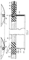
- the support shown in Figure 3, is separated in two parts by a middle flange 17D: the winding of the electromagnetic transducer is housed between said flange 17D and an end flange 17C while the spout 9 is formed by the thinned end of part 17A.
- the ends 18 of the winding are connected by conductive braids 21 to the supply terminals 19 ( Figure 2) which receive the electrical signal from an amplification chain of a sound or other signal.
- notches 33 (FIG. 2) which are diametrical, the bottom of which is pierced with a cylindrical hole 34 halfway through the ring.
- the tube is made of the same material as that provided for the molding of the rings.
- the notches which are also filled with elastomer provide greater flexibility to the electrical connection.
- the free part of the braid, extending diametrically from the crown, is fixed by known means on the terminals 19.
- the transducer unit has the following dimensions: inside diameter of the support: # 102 mm; ring height: # 16 mm; thickness of the part forming the modulation spout: # 1.5 mm.
- the large diameter of the support is made necessary by the large fluid flow rate, of the order of several tens of grams per second under pressures of 2 to 3 bars, which passes through the fluid amplifier.
- the support is particularly flexible and its retention in a conventional thin membrane cannot result in sufficient stiffening.
- the in situ molding of thick elastomer rings, secured to the outer and inner rings and the support, ensures effective hooping of the latter.
- the width of the rings is at least of the same order of magnitude as their thickness and, according to an exemplary embodiment, of the thickness of the crowns (approximately 4 mm).
- the molding product used is a commercial silicone elastomer, vulcanizing at room temperature, with a Shore A hardness of the order of 40, in a temperature range of -70 ° to + 200 ° C. This temperature range is chosen so that the material retains its hardness characteristics and therefore there is no change in the characteristics of the loudspeaker regardless of variations in the surrounding temperature or the temperature of the material. air supplied to the pneumatic circuit.
- the great stiffness of the chosen elastomer ensures a high resonant frequency, hence a relatively wide bandwidth and an interesting signal / noise ratio, that is to say of the order of 30 to 40 dB.
- the resonant frequencies can be chosen by varying the section of the rings and / or the hardness of the elastomer.
- the resonance frequency is 1200 Hz.
- the pneumatic loudspeaker comprising a mobile assembly in accordance with the invention, allows the passage of a frequency band of 5 KHz which guarantees a very good understanding of speech.
Landscapes
- Physics & Mathematics (AREA)
- Engineering & Computer Science (AREA)
- Acoustics & Sound (AREA)
- Signal Processing (AREA)
- Audible-Bandwidth Dynamoelectric Transducers Other Than Pickups (AREA)
- Diaphragms For Electromechanical Transducers (AREA)
- Reciprocating Pumps (AREA)
- Apparatuses For Generation Of Mechanical Vibrations (AREA)
Claims (7)
- Mobile Ausrüstung für den elektrodynamisch-fluidischen Wandler eines pneumatischen Lautsprechers mit einem axial beweglichen rohrförmigen Lager (17), von dem ein Ende eine mobile Spule (18) im ringförmigen Luftspalt (16) der elektrodynamischen Stufe des Wandlers trägt und von dem das andere Ende eine bewegliche Nase (9) in der Verengung eines ringförmigen Durchlasses der fluidischen Stufe des Wandlers bildet, wobei der Mittelteil des Lagers zwischen zwei konzentrische Membranen (22) eingespannt ist, die die elektrodynamische und fluidische Stufe des Wandlers voneinander trennen, dadurch gekennzeichnet, daß das Lager (17), das einen Durchmesser in einer über seiner Höhe liegenden Größenordnung und eine Höhe in einer über seiner Dicke liegenden Größenordnung aufweist, durch die erwähnten Membranen (22) versteift ist, wobei jede Membran durch ein zusammengesetztes Band gebildet ist, das zwischen dem Lager (17) und einer steifen konzentrischen Einfassung (23, 24) einen daran haftenden Elastomerring (22) einschließt, der eine axiale Höhe in der gleichen Größenordnung wie seine radiale Dicke aufweist, um einerseits die elastische Rückstellung des Lagers bei einer Axialverschiebung sicherzustellen und andererseits die Kreisförmigkeit und somit die Ebenheit des Lagers aufrechtzuerhalten.
- Ausrüstung nach Anspruch 1, dadurch gekennzeichnet, daß die besagten Elastomerringe (22) in situ zwischen dem Lager (17) und den Einfassungen (23, 24) unter Halterung durch geeignete Schablonen geformt sind.
- Mobile Ausrüstung nach Anspruch 2, dadurch gekennzeichnet, daß das Elastomer ein bei Raumtemperatur vulkanisierbares Silikon ist.
- Mobile Ausrüstung nach Anspruch 2 oder 3, dadurch gekennzeichnet, daß das Elastomer eine Shore A-Härte in einer Größenordnung von 40 in einem Temperaturbereich von -70 bis 200 °C aufweist.
- Mobile Ausrüstung nach einem der Ansprüche 2 bis 4, dadurch gekennzeichnet, daß das Elastomer zwei nachgiebige Rohre einschließt, die sich durch das Lager (17) und die äußere Einfassung (23) erstrecken, um den Durchgang von Anschlüssen (21) der beweglichen Spule (18) zu ermöglichen.
- Mobile Ausrüstung nach Anspruch 5, dadurch gekennzeichnet, daß die Einfassung (23) rechts von jedem Anschluß (21) einen mit Elastomer gefüllten Ausschnitt (33) aufweist, über den sich das Rohr erstreckt.
- Mobile Ausrüstung nach Anspruch 1, dadurch gekennzeichnet, daß ein ringförmiges Widerlager (35) aus Elastomer in dem Teil der Düse (4) vorgesehen ist, die der beweglichen Nase (9) gegenüberliegt.
Priority Applications (1)
| Application Number | Priority Date | Filing Date | Title |
|---|---|---|---|
| AT89402667T ATE91371T1 (de) | 1988-09-29 | 1989-09-28 | Elektrodynamisch-fluidische wandlerausruestung fuer einen pneumatischen lautsprecher. |
Applications Claiming Priority (2)
| Application Number | Priority Date | Filing Date | Title |
|---|---|---|---|
| FR8812734A FR2637148B1 (fr) | 1988-09-29 | 1988-09-29 | Equipage transducteur electrodynamique-fluidique pour haut-parleur pneumatique |
| FR8812734 | 1988-09-29 |
Publications (2)
| Publication Number | Publication Date |
|---|---|
| EP0362068A1 EP0362068A1 (de) | 1990-04-04 |
| EP0362068B1 true EP0362068B1 (de) | 1993-07-07 |
Family
ID=9370526
Family Applications (1)
| Application Number | Title | Priority Date | Filing Date |
|---|---|---|---|
| EP89402667A Expired - Lifetime EP0362068B1 (de) | 1988-09-29 | 1989-09-28 | Elektrodynamisch-fluidische Wandlerausrüstung für einen pneumatischen Lautsprecher |
Country Status (9)
| Country | Link |
|---|---|
| US (1) | US5179595A (de) |
| EP (1) | EP0362068B1 (de) |
| JP (1) | JPH04500893A (de) |
| KR (1) | KR900702745A (de) |
| AT (1) | ATE91371T1 (de) |
| DE (1) | DE68907460T2 (de) |
| ES (1) | ES2044176T3 (de) |
| FR (1) | FR2637148B1 (de) |
| WO (1) | WO1990003708A1 (de) |
Families Citing this family (3)
| Publication number | Priority date | Publication date | Assignee | Title |
|---|---|---|---|---|
| FR2697396A1 (fr) * | 1992-10-28 | 1994-04-29 | Bernard Francis | Enceinte acoustique au son omnidirectionnel et au son soufflé par air. |
| US10631093B2 (en) * | 2015-01-26 | 2020-04-21 | Harman International Industries, Incorporated | Vented loudspeaker system with duct for cooling of internal components |
| US9571935B2 (en) * | 2015-01-26 | 2017-02-14 | Harman International Industries, Inc. | Loudspeaker with ducts for transducer voice coil cooling |
Family Cites Families (6)
| Publication number | Priority date | Publication date | Assignee | Title |
|---|---|---|---|---|
| US3073916A (en) * | 1958-11-24 | 1963-01-15 | Muter Company | Blast-proof water-proof loudspeaker |
| US3674945A (en) * | 1970-03-11 | 1972-07-04 | Raytheon Co | Acoustic impedance matching system |
| US4055233A (en) * | 1975-12-22 | 1977-10-25 | Electronic Engineering Co. Of California | Ear coupler |
| FR2442565A1 (fr) * | 1978-11-24 | 1980-06-20 | Bertin & Cie | Procede d'amplification acoustique fluide et haut parleur pneumatique de mise en oeuvre de ce procede |
| FR2572615B1 (fr) * | 1984-10-29 | 1988-10-14 | Bertin & Cie | Haut-parleur pneumatique a debit continu de fluide sous pression |
| US4696045A (en) * | 1985-06-04 | 1987-09-22 | Acr Electronics | Ear microphone |
-
1988
- 1988-09-29 FR FR8812734A patent/FR2637148B1/fr not_active Expired - Lifetime
-
1989
- 1989-09-28 AT AT89402667T patent/ATE91371T1/de not_active IP Right Cessation
- 1989-09-28 EP EP89402667A patent/EP0362068B1/de not_active Expired - Lifetime
- 1989-09-28 ES ES89402667T patent/ES2044176T3/es not_active Expired - Lifetime
- 1989-09-28 DE DE89402667T patent/DE68907460T2/de not_active Expired - Fee Related
- 1989-09-28 US US07/659,418 patent/US5179595A/en not_active Expired - Fee Related
- 1989-09-28 KR KR1019900701082A patent/KR900702745A/ko not_active Withdrawn
- 1989-09-28 WO PCT/FR1989/000498 patent/WO1990003708A1/fr not_active Ceased
- 1989-09-28 JP JP1510789A patent/JPH04500893A/ja active Pending
Also Published As
| Publication number | Publication date |
|---|---|
| EP0362068A1 (de) | 1990-04-04 |
| DE68907460D1 (de) | 1993-08-12 |
| ES2044176T3 (es) | 1994-01-01 |
| US5179595A (en) | 1993-01-12 |
| DE68907460T2 (de) | 1994-03-03 |
| FR2637148B1 (fr) | 1991-06-07 |
| FR2637148A1 (fr) | 1990-03-30 |
| KR900702745A (ko) | 1990-12-08 |
| WO1990003708A1 (fr) | 1990-04-05 |
| ATE91371T1 (de) | 1993-07-15 |
| JPH04500893A (ja) | 1992-02-13 |
Similar Documents
| Publication | Publication Date | Title |
|---|---|---|
| CA2446972C (fr) | Emetteur de son et haut-parleur | |
| EP0002161B1 (de) | Piezoelektrischer Übertrager und Verfahren zu seiner Herstellung | |
| EP0045265A2 (de) | Sonde für Echographie mit mechanischer Sektorabtastung | |
| FR2520962A1 (fr) | Transducteur a membrane plate et procede de realisation de ce transducteur | |
| FR2522240A1 (fr) | Diaphragme de haut-parleur | |
| EP0362068B1 (de) | Elektrodynamisch-fluidische Wandlerausrüstung für einen pneumatischen Lautsprecher | |
| FR2556164A1 (fr) | Haut-parleur | |
| CH691334A5 (fr) | Appareillage susceptible d'être immergé et comprenant un transducteur sonore. | |
| FR2572615A1 (fr) | Haut-parleur pneumatique a debit continu de fluide sous pression | |
| FR2747004A1 (fr) | Convertisseur electrostatique | |
| EP0012070B1 (de) | Pneumatischer Lautsprecher mit konstantem Fluidfluss | |
| EP0899634B1 (de) | Vorrichtung zur Verwendung unter Wasser und mit einem Schallwandler | |
| FR3052624B1 (fr) | Transducteur electrodynamique large bande pour casque audio et casque audio associe | |
| FR2519502A1 (fr) | Mo | |
| EP0403378B1 (de) | Kugelmembran-Rundstrahllautsprecher mit magnetostriktivem Doppelschicht-Bändchen | |
| EP0899635B1 (de) | Vorrichtung zur Verwendung unter Wasser und mit einem Schallwandler | |
| FR3087068A1 (fr) | Haut-parleur electrodynamique comportant un treillis | |
| EP0629334B1 (de) | Miniaturisierter optoakustischer wandler | |
| MC1049A1 (fr) | Haut-parleurs électrodynamiques | |
| FR2490439A1 (fr) | Transducteur electrodynamique en particulier pour la telephonie | |
| BE406138A (de) | ||
| CH224072A (fr) | Récepteur téléphonique. | |
| EP0066027A1 (de) | Membran, insbesondere für einen elektroakustischen Wandler | |
| WO1993014609A1 (fr) | Capteur optique de vibrations | |
| CA2751117A1 (fr) | Equipage mobile et transducteur electrodynamique pourvu d'un tel equipage mobile |
Legal Events
| Date | Code | Title | Description |
|---|---|---|---|
| PUAI | Public reference made under article 153(3) epc to a published international application that has entered the european phase |
Free format text: ORIGINAL CODE: 0009012 |
|
| AK | Designated contracting states |
Kind code of ref document: A1 Designated state(s): AT BE CH DE ES FR GB GR IT LI LU NL SE |
|
| 17P | Request for examination filed |
Effective date: 19900827 |
|
| 17Q | First examination report despatched |
Effective date: 19921028 |
|
| GRAA | (expected) grant |
Free format text: ORIGINAL CODE: 0009210 |
|
| AK | Designated contracting states |
Kind code of ref document: B1 Designated state(s): AT BE CH DE ES FR GB GR IT LI LU NL SE |
|
| REF | Corresponds to: |
Ref document number: 91371 Country of ref document: AT Date of ref document: 19930715 Kind code of ref document: T |
|
| REF | Corresponds to: |
Ref document number: 68907460 Country of ref document: DE Date of ref document: 19930812 |
|
| GBT | Gb: translation of ep patent filed (gb section 77(6)(a)/1977) |
Effective date: 19930730 |
|
| ITF | It: translation for a ep patent filed | ||
| REG | Reference to a national code |
Ref country code: GR Ref legal event code: FG4A Free format text: 3008440 |
|
| EPTA | Lu: last paid annual fee | ||
| REG | Reference to a national code |
Ref country code: ES Ref legal event code: FG2A Ref document number: 2044176 Country of ref document: ES Kind code of ref document: T3 |
|
| PLBE | No opposition filed within time limit |
Free format text: ORIGINAL CODE: 0009261 |
|
| STAA | Information on the status of an ep patent application or granted ep patent |
Free format text: STATUS: NO OPPOSITION FILED WITHIN TIME LIMIT |
|
| 26N | No opposition filed | ||
| EAL | Se: european patent in force in sweden |
Ref document number: 89402667.3 |
|
| PGFP | Annual fee paid to national office [announced via postgrant information from national office to epo] |
Ref country code: GR Payment date: 19950831 Year of fee payment: 7 |
|
| PGFP | Annual fee paid to national office [announced via postgrant information from national office to epo] |
Ref country code: LU Payment date: 19950901 Year of fee payment: 7 |
|
| PGFP | Annual fee paid to national office [announced via postgrant information from national office to epo] |
Ref country code: ES Payment date: 19950914 Year of fee payment: 7 |
|
| PGFP | Annual fee paid to national office [announced via postgrant information from national office to epo] |
Ref country code: SE Payment date: 19950927 Year of fee payment: 7 Ref country code: CH Payment date: 19950927 Year of fee payment: 7 |
|
| PGFP | Annual fee paid to national office [announced via postgrant information from national office to epo] |
Ref country code: AT Payment date: 19950930 Year of fee payment: 7 |
|
| PGFP | Annual fee paid to national office [announced via postgrant information from national office to epo] |
Ref country code: BE Payment date: 19951009 Year of fee payment: 7 |
|
| PG25 | Lapsed in a contracting state [announced via postgrant information from national office to epo] |
Ref country code: LU Free format text: LAPSE BECAUSE OF NON-PAYMENT OF DUE FEES Effective date: 19960928 Ref country code: AT Effective date: 19960928 |
|
| PG25 | Lapsed in a contracting state [announced via postgrant information from national office to epo] |
Ref country code: SE Effective date: 19960929 |
|
| PG25 | Lapsed in a contracting state [announced via postgrant information from national office to epo] |
Ref country code: LI Effective date: 19960930 Ref country code: ES Free format text: LAPSE BECAUSE OF THE APPLICANT RENOUNCES Effective date: 19960930 Ref country code: CH Effective date: 19960930 Ref country code: BE Effective date: 19960930 |
|
| BERE | Be: lapsed |
Owner name: BERTIN & CIE Effective date: 19960930 |
|
| PG25 | Lapsed in a contracting state [announced via postgrant information from national office to epo] |
Ref country code: GR Free format text: THE PATENT HAS BEEN ANNULLED BY A DECISION OF A NATIONAL AUTHORITY Effective date: 19970331 |
|
| REG | Reference to a national code |
Ref country code: GR Ref legal event code: MM2A Free format text: 3008440 |
|
| REG | Reference to a national code |
Ref country code: CH Ref legal event code: PL |
|
| EUG | Se: european patent has lapsed |
Ref document number: 89402667.3 |
|
| REG | Reference to a national code |
Ref country code: ES Ref legal event code: FD2A Effective date: 19991007 |
|
| REG | Reference to a national code |
Ref country code: GB Ref legal event code: IF02 |
|
| REG | Reference to a national code |
Ref country code: FR Ref legal event code: TP |
|
| PGFP | Annual fee paid to national office [announced via postgrant information from national office to epo] |
Ref country code: NL Payment date: 20030825 Year of fee payment: 15 |
|
| PGFP | Annual fee paid to national office [announced via postgrant information from national office to epo] |
Ref country code: GB Payment date: 20030829 Year of fee payment: 15 |
|
| PGFP | Annual fee paid to national office [announced via postgrant information from national office to epo] |
Ref country code: DE Payment date: 20030909 Year of fee payment: 15 |
|
| PGFP | Annual fee paid to national office [announced via postgrant information from national office to epo] |
Ref country code: FR Payment date: 20030925 Year of fee payment: 15 |
|
| PG25 | Lapsed in a contracting state [announced via postgrant information from national office to epo] |
Ref country code: GB Free format text: LAPSE BECAUSE OF NON-PAYMENT OF DUE FEES Effective date: 20040928 |
|
| PG25 | Lapsed in a contracting state [announced via postgrant information from national office to epo] |
Ref country code: NL Free format text: LAPSE BECAUSE OF NON-PAYMENT OF DUE FEES Effective date: 20050401 Ref country code: DE Free format text: LAPSE BECAUSE OF NON-PAYMENT OF DUE FEES Effective date: 20050401 |
|
| GBPC | Gb: european patent ceased through non-payment of renewal fee |
Effective date: 20040928 |
|
| PG25 | Lapsed in a contracting state [announced via postgrant information from national office to epo] |
Ref country code: FR Free format text: LAPSE BECAUSE OF NON-PAYMENT OF DUE FEES Effective date: 20050531 |
|
| NLV4 | Nl: lapsed or anulled due to non-payment of the annual fee |
Effective date: 20050401 |
|
| REG | Reference to a national code |
Ref country code: FR Ref legal event code: ST |
|
| PG25 | Lapsed in a contracting state [announced via postgrant information from national office to epo] |
Ref country code: IT Free format text: LAPSE BECAUSE OF NON-PAYMENT OF DUE FEES Effective date: 20050928 |