EP0362098B1 - Schere zum Betonbrechen - Google Patents
Schere zum Betonbrechen Download PDFInfo
- Publication number
- EP0362098B1 EP0362098B1 EP89450013A EP89450013A EP0362098B1 EP 0362098 B1 EP0362098 B1 EP 0362098B1 EP 89450013 A EP89450013 A EP 89450013A EP 89450013 A EP89450013 A EP 89450013A EP 0362098 B1 EP0362098 B1 EP 0362098B1
- Authority
- EP
- European Patent Office
- Prior art keywords
- nippers
- concrete
- arms
- arm
- breaking
- Prior art date
- Legal status (The legal status is an assumption and is not a legal conclusion. Google has not performed a legal analysis and makes no representation as to the accuracy of the status listed.)
- Expired - Lifetime
Links
Images



Classifications
-
- E—FIXED CONSTRUCTIONS
- E02—HYDRAULIC ENGINEERING; FOUNDATIONS; SOIL SHIFTING
- E02F—DREDGING; SOIL-SHIFTING
- E02F3/00—Dredgers; Soil-shifting machines
- E02F3/04—Dredgers; Soil-shifting machines mechanically-driven
- E02F3/28—Dredgers; Soil-shifting machines mechanically-driven with digging tools mounted on a dipper- or bucket-arm, i.e. there is either one arm or a pair of arms, e.g. dippers, buckets
- E02F3/36—Component parts
- E02F3/3604—Devices to connect tools to arms, booms or the like
- E02F3/3677—Devices to connect tools to arms, booms or the like allowing movement, e.g. rotation or translation, of the tool around or along another axis as the movement implied by the boom or arms, e.g. for tilting buckets
- E02F3/3681—Rotators
-
- E—FIXED CONSTRUCTIONS
- E02—HYDRAULIC ENGINEERING; FOUNDATIONS; SOIL SHIFTING
- E02F—DREDGING; SOIL-SHIFTING
- E02F3/00—Dredgers; Soil-shifting machines
- E02F3/04—Dredgers; Soil-shifting machines mechanically-driven
- E02F3/96—Dredgers; Soil-shifting machines mechanically-driven with arrangements for alternate or simultaneous use of different digging elements
- E02F3/965—Dredgers; Soil-shifting machines mechanically-driven with arrangements for alternate or simultaneous use of different digging elements of metal-cutting or concrete-crushing implements
-
- E—FIXED CONSTRUCTIONS
- E04—BUILDING
- E04G—SCAFFOLDING; FORMS; SHUTTERING; BUILDING IMPLEMENTS OR AIDS, OR THEIR USE; HANDLING BUILDING MATERIALS ON THE SITE; REPAIRING, BREAKING-UP OR OTHER WORK ON EXISTING BUILDINGS
- E04G23/00—Working measures on existing buildings
- E04G23/08—Wrecking of buildings
-
- E—FIXED CONSTRUCTIONS
- E04—BUILDING
- E04G—SCAFFOLDING; FORMS; SHUTTERING; BUILDING IMPLEMENTS OR AIDS, OR THEIR USE; HANDLING BUILDING MATERIALS ON THE SITE; REPAIRING, BREAKING-UP OR OTHER WORK ON EXISTING BUILDINGS
- E04G23/00—Working measures on existing buildings
- E04G23/08—Wrecking of buildings
- E04G23/082—Wrecking of buildings using shears, breakers, jaws and the like
-
- Y—GENERAL TAGGING OF NEW TECHNOLOGICAL DEVELOPMENTS; GENERAL TAGGING OF CROSS-SECTIONAL TECHNOLOGIES SPANNING OVER SEVERAL SECTIONS OF THE IPC; TECHNICAL SUBJECTS COVERED BY FORMER USPC CROSS-REFERENCE ART COLLECTIONS [XRACs] AND DIGESTS
- Y10—TECHNICAL SUBJECTS COVERED BY FORMER USPC
- Y10T—TECHNICAL SUBJECTS COVERED BY FORMER US CLASSIFICATION
- Y10T225/00—Severing by tearing or breaking
- Y10T225/20—Severing by manually forcing against fixed edge
- Y10T225/22—With means to move work toward or into severing position
-
- Y—GENERAL TAGGING OF NEW TECHNOLOGICAL DEVELOPMENTS; GENERAL TAGGING OF CROSS-SECTIONAL TECHNOLOGIES SPANNING OVER SEVERAL SECTIONS OF THE IPC; TECHNICAL SUBJECTS COVERED BY FORMER USPC CROSS-REFERENCE ART COLLECTIONS [XRACs] AND DIGESTS
- Y10—TECHNICAL SUBJECTS COVERED BY FORMER USPC
- Y10T—TECHNICAL SUBJECTS COVERED BY FORMER US CLASSIFICATION
- Y10T225/00—Severing by tearing or breaking
- Y10T225/30—Breaking or tearing apparatus
- Y10T225/371—Movable breaking tool
Definitions
- the present invention relates to a concrete breaker pliers.
- This type of tool is used for the demolition of reinforced concrete structures and generally mounted at the end of the boom of a hydraulic shovel instead of a bucket.
- These devices generally consist of a jaw with two arms fitted with teeth, articulated on a frame which is itself rotatably mounted and further comprise a shear arranged between the arms and capable of cutting the irons and other metal fittings.
- shears are impractical to use and ineffective. Indeed, the shears are located at the bottom of the jaw and in the immediate vicinity of one of the arms of the jaw which constitutes one of the two sectioning members of said shears.
- the introduction of the irons to be cut inside the shears is difficult because the latter is located at the bottom of the pliers in a place which is very difficult to see from the control cabin of the machine; in addition, the opening of the shears is very small so that it is necessary to work, most of the time, blind, grope to engage the irons and to repeat it several times to cut a bundle of irons. Finally, the maximum opening of the shears being obtained by the maximum opening of the pliers, this can pose serious problems when it is necessary to cut irons in small, congested or narrow access spaces.
- Document DE-A-2,722,258 also discloses pliers provided with shears. However, it is a device comprising a common, fixed jaw arm, cooperating with a gripper arm and a shear arm arranged in parallel and controlled independently.
- the object of the present invention is to overcome these various drawbacks by proposing another combination of means ensuring both the function of concrete clamps and the shears function, in a much more practical and efficient manner.
- the subject of the invention is a concrete breaker clamp of the type comprising a frame mounted to rotate, carrying both two clamp arms, at least one of which is movable relative to the frame and shearing members, characterized in that said frame is formed of two flanges and in that the shearing members are mounted, on the one hand, on at least one fixed arm formed by an extension of one of the flanges and, on the other hand, on said movable arm of the clamp, said fixed and movable arm being in side-by-side position in the position of maximum opening of the clamp, so as to give the shears its maximum closure in this position.
- Such a device is much easier to handle and effective because the shears are located at the end of the pliers and no longer at the bottom or on the external lateral side of the pliers. Its opening is much larger and corresponds to the minimum spacing of the clamp, which makes it possible to shear in one go, after a direct, frank and without engagement groping, several grouped irons. Finally, a single cylinder controls both the pliers and the shears.
- the invention also aims to improve the efficiency of the shears and pliers organs by allowing easy adjustment and / or replacement of the blades or teeth.
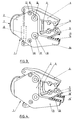
- the concrete breaker pliers illustrated in FIGS. 1 to 3 comprises a frame 1 formed by two flanges 2 and 3 on and between which two arms 4 and 5 concrete breakers are articulated.
- the assembly 1-5 is mounted infinitely rotatable, by hydraulic motor and rotating joint, on an adapter part 6 of conventional design, intended to be mounted, in the known manner, at the end of the boom of a shovel mechanical for example. Between the part 6 and the frame 1 is interposed the rotation device with its fixed ball ring 7; hydraulic regulation supporting untimely efforts on the rotation control assembly.
- the arms 4 and 5 constitute levers flanked by pins 8 and 9 engaged in bearings 10 produced in the two flanges 2 and 3.
- the angular movement of the arms 4 and 5 is limited by a stop 13 integral with the frame 1 and an arcuate opening 14 formed in each arm and in which the stop 13 can slide.
- One of the flanges (2) has, on one side, an extension in the form of an arm 14, the end of which constitutes one of the arms of a shear, the other arm of which is formed by the arm 5 of the pliers .
- the active members of the shears consist of cutting blades 15 and 16 mounted removable respectively on the flanks opposite the arms 5 and 14 respectively.
- the arrangement of the arm 14 is such that in the position of maximum closing of the clamp (4, 5) as illustrated in FIGS. 1 and 3, the opening of the shears (5, 14) is maximum, while in the maximum open position of the clamp ( Figure 2), the shears are completely closed.
- the blades 15 and 16 are arranged at the ends of the arms 5 and 14 in order to grip the irons with the largest possible opening and greater ease of access to and grip of the irons.
- FIG. 7 illustrates the shape and mounting of the blades 15 and 16.
- These consist, in accordance with the invention, of an elongated plate provided on one of its faces with a series of teeth 17 whose profile asymmetrical is determined so as to retain the irons in the shears and prevent them from sliding outside when the arms 5, 14 are closed.
- each tooth 17 comprises a side 17a substantially vertical, with respect to the general plane of the blade plate, a side 17b slightly inclined towards the outside of the shears and a heater 17c for connection between the two sides 17a. , 17b, avoiding any sharp edge and therefore fragile at the end of the teeth.
- the removable mounting of the blades 15 and 16 allows a re-sharpening of the cutting edge by grinding one of the lateral sides of the blades.
- the teeth 11 of the concrete breaker are preferably made up of parts (FIG. 8) comprising a frustoconical anchoring foot 19 engaged in a housing of corresponding shape formed in the receiving arm (4, 5) and retained in place by a group 20
- This assembly makes it possible to transfer onto said frustoconical housing all of the forces exerted on the tooth 11, the external part 21 of which is slightly set back from the face opposite the support arm.
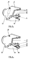
- FIG. 4 illustrates a variant of the device of FIG. 3 according to which a second arm 14 ′, parallel to the arm 14, is provided by means of an extension of the flange 3.
- This arm 14 ′ is provided with a blade section 16 ′ parallel to the blade 16, the arm 5 of the clamp moving between the two fixed arms 14, 14 ′.
- the concrete breaker pliers comprises a movable arm 5 also constituting one of the elements of the shears, exactly as in the embodiment of FIG. 3, but this arm 5 cooperates with a arm 4 ′ fixed, no longer mobile, and formed from an extension of the two flanges 2 and 3.
- the cylinder 12 for controlling the arm 5 is anchored at 22 to the frame 1.
- Figure 6 illustrates a variant of the device of Figure 5 in which the fixed arm 14 of the shears is lined with a second fixed arm 14 ′ as in the embodiment of Figure 4, the frame 1 thus having a general shape of U.
- the invention is obviously not limited to the embodiments shown and described above, but on the contrary covers all variants thereof, in particular as regards the shapes and arrangements of the blades 16, the teeth 11 and the various arms 4, 5, 14, 4 ′, 14 ′.
Landscapes
- Engineering & Computer Science (AREA)
- Architecture (AREA)
- Structural Engineering (AREA)
- Mechanical Engineering (AREA)
- Civil Engineering (AREA)
- Mining & Mineral Resources (AREA)
- General Engineering & Computer Science (AREA)
- Chemical Kinetics & Catalysis (AREA)
- Chemical & Material Sciences (AREA)
- Electrochemistry (AREA)
- Working Measures On Existing Buildindgs (AREA)
- Crushing And Grinding (AREA)
- Scissors And Nippers (AREA)
- Polysaccharides And Polysaccharide Derivatives (AREA)
- Organic Low-Molecular-Weight Compounds And Preparation Thereof (AREA)
- Curing Cements, Concrete, And Artificial Stone (AREA)
- Placing Or Removing Of Piles Or Sheet Piles, Or Accessories Thereof (AREA)
- Memory System Of A Hierarchy Structure (AREA)
- Shovels (AREA)
Claims (9)
- Schere zum Betonbrechen des Typs umfassend einen drehbar montierten Rahmen (1), der zugleich zwei Scherenarme (4, 5), von denen wenigstens der eine (5) in bezug auf den Rahmen beweglich ist, und Abscherorgane (15, 16, 16') trägt, dadurch gekennzeichnet, daß besagter Rahmen durch zwei Platten (2, 3) gebildet wird und daß die Abscherorgane einerseits (16, 16') auf wenigstens einem feststehenden Scherenarm (14), der durch eine Verlängerung der einen (2) der Platten gebildet wird, und andererseits (15) an besagten beweglichen Scherenarm (5) montiert sind, wobei die besagten feststehenden und beweglichen Arme (14 und 5) bei maximaler Öffnungsposition der Schere sich in einer Position Seite an Seite derart befinden, daß dem Abscherer (5, 14) sein maximales Schließen in dieser Position verliehen wird.
- Schere zum Betonbrechen nach Anspruch 1, dadurch gekennzeichnet, daß die beiden Scherenarme (4, 5) an dem Rahmen (1) angelenkt sind.
- Schere zum Betonbrechen nach Anspruch 1 oder 2, dadurch gekennzeichnet, daß die beiden Scherenarme (4, 5) Hebel bilden, deren Enden, die den mit Brechzähnen (11) versehenen Enden gegenüberliegen, durch einen doppeltwirkenden Hydraulikzylinder (12) verbunden sind, wobei besagte Hebel frei drehbar mit dem Rahmen (1) verbunden und mit Anschlagorganen (13, 13') versehen sind, die die Winkelbewegung besagter Arme begrenzen.
- Schere zum Betonbrechen nach einem der Ansprüche 1 bis 3, dadurch gekennzeichnet, daß besagter feststehender Arm (14) durch einen zweiten parallelen feststehenden Arm (14') verdoppelt ist, wobei besagter Arm (5), der die Funktionen des Betonbrechens und Abscherens sicherstellt, zwischen den beiden oben genannten Armen (14, 14') beweglich montiert ist.
- Schere zum Betonbrechen nach Anspruch 1, dadurch gekennzeichnet, daß der Scherenarm (4') anders als derjenige (5), der die Funktionen des Betonbrechens und Abscherens sicherstellt, feststehend ist.
- Schere zum Betonbrechen nach Anspruch 5, dadurch gekennzeichnet, daß besagter feststehender Scherenarm (4') durch eine Verlängerung von Montageplatten (2, 3) für Scherenarme (4, 5) gebildet ist.
- Schere zum Betonbrechen nach Anspruch 5 oder 6, dadurch gekennzeichnet, daß der feststehende Arm (14), der eines der Abscherelemente bildet, durch einen zweiten parallelen feststehenden Arm (14') verdoppelt ist, wobei besagter Scherenarm (5), der die Funktionen des Betonbrechens und Abscherens sicherstellt, beweglich zwischen den beiden oben genannten Armen (14, 14') angeordnet ist.
- Schere zum Betonbrechen nach einem der Ansprüche 1 bis 7, dadurch gekennzeichnet, daß die Schneidplatten (15, 16, 16') zum Abscheren auswechselbar sind und Platten mit Zähnen (17) mit asymmetrischem Profil (17a, 17b) bilden, die in ihrer Position auf den Armen (5, 14, 14') einstellbar montiert sind.
- Schere zum Betonbrechen nach einem der Ansprüche 1 bis 8, dadurch gekennzeichnet, daß die Scherenarme (4, 4', 5) Zähne (11) tragen, die Verankerungsfüße (19) aufweisen, die durch Stifte (20) in Sitzen geeigneter Form gehalten sind, die die Gesamtheit von auf besagte Zähne (11) ausgeübten Kräfte aufnehmen.
Priority Applications (1)
| Application Number | Priority Date | Filing Date | Title |
|---|---|---|---|
| AT8989450013T ATE105354T1 (de) | 1988-09-30 | 1989-09-29 | Schere zum betonbrechen. |
Applications Claiming Priority (2)
| Application Number | Priority Date | Filing Date | Title |
|---|---|---|---|
| FR8812994 | 1988-09-30 | ||
| FR8812994A FR2637303B1 (fr) | 1988-09-30 | 1988-09-30 | Pince brise-beton |
Publications (2)
| Publication Number | Publication Date |
|---|---|
| EP0362098A1 EP0362098A1 (de) | 1990-04-04 |
| EP0362098B1 true EP0362098B1 (de) | 1994-05-04 |
Family
ID=9370682
Family Applications (1)
| Application Number | Title | Priority Date | Filing Date |
|---|---|---|---|
| EP89450013A Expired - Lifetime EP0362098B1 (de) | 1988-09-30 | 1989-09-29 | Schere zum Betonbrechen |
Country Status (8)
| Country | Link |
|---|---|
| US (1) | US4951886A (de) |
| EP (1) | EP0362098B1 (de) |
| JP (1) | JP3061388B2 (de) |
| KR (1) | KR900005033A (de) |
| AT (1) | ATE105354T1 (de) |
| CA (1) | CA1335443C (de) |
| DE (1) | DE68915100T2 (de) |
| FR (1) | FR2637303B1 (de) |
Families Citing this family (46)
| Publication number | Priority date | Publication date | Assignee | Title |
|---|---|---|---|---|
| US5004168A (en) * | 1989-11-13 | 1991-04-02 | Brian Purser | Crushing apparatus |
| US5044569A (en) * | 1989-12-15 | 1991-09-03 | Labounty Roy E | Rock and coral demolition tool |
| DE4013126A1 (de) * | 1990-04-25 | 1991-10-31 | Helmut Wack | Abbruchgeraet |
| DE4022689A1 (de) * | 1990-05-31 | 1991-12-05 | Rolf Mieger | Loeffel |
| US5044568A (en) * | 1990-08-20 | 1991-09-03 | Takachiho Kogyo Yuugen Kaisha | Hand crusher with rotatably mounted handle |
| USD332791S (en) | 1990-09-10 | 1993-01-26 | Stone Import & Development Co., Ltd. | Concrete crusher |
| US5187868A (en) * | 1992-06-16 | 1993-02-23 | Hall Charlie R | Metal demolition shear |
| JP3063940B2 (ja) * | 1992-07-07 | 2000-07-12 | 株式会社坂戸工作所 | 天然砕石塊破砕システム |
| DE9210292U1 (de) * | 1992-07-31 | 1992-10-22 | Mieger, Rolf, 7951 Kirchdorf | Werkzeug für Arbeitsmaschinen |
| JPH0657970A (ja) * | 1992-08-10 | 1994-03-01 | Ooyodo Diesel Kk | コンクリート破砕機 |
| JP2585939B2 (ja) * | 1993-01-26 | 1997-02-26 | 大淀小松株式会社 | 破砕装置 |
| JP2577181B2 (ja) * | 1993-06-16 | 1997-01-29 | 大淀ヂ−ゼル株式会社 | 万能解体機 |
| US5474242A (en) * | 1994-10-11 | 1995-12-12 | The Stanley Works | Demolition tools with jaws having replaceable working surfaces |
| FR2735709B1 (fr) * | 1995-06-26 | 1997-08-14 | Dorguin Jean Pierre | Dispositif de cisaillement, notamment pour la coupe de metaux ou de beton |
| US5626457A (en) * | 1995-11-20 | 1997-05-06 | Action Machinery Company Of Alabama, Inc. | Grapple impactor |
| AT403491B (de) * | 1996-02-15 | 1998-02-25 | Wimmer Alois Ing | Betonbrechzange mit schneidschere |
| JP3156754B2 (ja) * | 1996-10-15 | 2001-04-16 | 大淀ヂーゼル株式会社 | 破砕装置 |
| US5894666A (en) * | 1997-03-17 | 1999-04-20 | Npk Research, Inc. | Cutting and piercing tips for a metal cutting shear |
| DE59800062D1 (de) * | 1998-04-06 | 2000-01-13 | Thyssen Henschel Gmbh | Werkzeug für den Anbau an Manipulatoren zur Handhabung und/oder Bearbeitung von Werkstücken vzw. von Gussteilen |
| US6119970A (en) * | 1998-11-25 | 2000-09-19 | Genesis Equipment & Manufacturing, Inc. | Heavy-duty demolition apparatus with replaceable crushing and shearing tip |
| US6061911A (en) * | 1998-11-25 | 2000-05-16 | Genesis Equipment And Manufacturing Co. | Heavy-duty demolition apparatus with blade stabilizing device |
| US6926217B1 (en) | 1998-11-25 | 2005-08-09 | Genesis Attachments, Llc | Heavy-duty demolition apparatus with replaceable tip and rotatable cross blade |
| US7954742B2 (en) * | 1999-10-15 | 2011-06-07 | Ramun John R | Dual purpose adapter for a multiple tool attachment system |
| US6994284B1 (en) * | 1999-10-15 | 2006-02-07 | Ramun John R | Multiple tool attachment system |
| US8308092B2 (en) * | 1999-10-15 | 2012-11-13 | Ramun John R | Multiple tool attachment system with universal body with grapple |
| ATE234970T1 (de) * | 1999-12-30 | 2003-04-15 | Franz Muri | Betonbrechzange |
| GB0111519D0 (en) * | 2001-05-11 | 2001-07-04 | Purser Brian | Breaking apparatus |
| US6839969B2 (en) | 2002-11-18 | 2005-01-11 | Genesis Equipment And Manufacturing, Inc. | Replaceable demolition shear piercing tip |
| US8146256B2 (en) | 2003-10-31 | 2012-04-03 | Stanley Black & Decker, Inc. | Metal demolition shears with indexable, integrated wear plate/piercing tip |
| US7216575B2 (en) * | 2004-03-29 | 2007-05-15 | Genesis Attachments, Llc | Heavy-duty demolition apparatus with blade stabilizing puck |
| US7284718B2 (en) * | 2005-06-29 | 2007-10-23 | Genesis Attachments, Llc | Excavator demolition attachment with interchangeable jaw assemblies |
| US7264190B2 (en) * | 2005-07-05 | 2007-09-04 | Construction Equipment Company | Material breaker system |
| US20070145171A1 (en) * | 2005-12-23 | 2007-06-28 | The Stanley Works | Rebar cutting shears |
| US8702024B2 (en) * | 2008-04-16 | 2014-04-22 | Apopka Recycling, Inc. | Roller jaw crusher system and method |
| WO2010133862A2 (en) * | 2009-05-19 | 2010-11-25 | Michael John Williams | Pile cropping apparatus |
| US8231071B2 (en) * | 2009-08-07 | 2012-07-31 | John R. Ramun | Blade set for jaws used in rail breaking demolition equipment |
| US8628035B2 (en) * | 2009-08-07 | 2014-01-14 | John R. Ramun | Blade set for jaws used in rail breaking demolition equipment |
| JP3168361U (ja) * | 2011-03-29 | 2011-06-09 | 株式会社むすび倶楽部 | 紙製注連縄又は紙製リース |
| US8646709B2 (en) | 2012-04-11 | 2014-02-11 | John R. Ramun | Jaw set with serrated cutting blades |
| US8800902B2 (en) * | 2012-06-04 | 2014-08-12 | Seung Hwan KO | Attachment with interchangeable jaw |
| USD752114S1 (en) * | 2012-06-04 | 2016-03-22 | Caterpillar Work Tools B.V. | Multi-processor and modular wear protection system |
| EP2672021B1 (de) * | 2012-06-07 | 2016-08-31 | Caterpillar Work Tools B. V. | Backenbaugruppe für ein abbruchwerkzeug |
| EP3149248B1 (de) * | 2014-05-27 | 2020-07-01 | Savonlinnan Pr-urakointi OY | Vorrichtung zum abreissen einer betonstruktur |
| USD748694S1 (en) * | 2015-03-19 | 2016-02-02 | Buckhurst Group Limited | Pipe-crushing apparatus |
| FI127105B (fi) | 2016-11-25 | 2017-11-15 | Savonlinnan Pr-Urakointi Oy | Purkulaite ja työkone betonirakenteen purkamiseksi |
| FI130556B (fi) * | 2017-02-28 | 2023-11-17 | Savonlinnan Pr Urakointi Oy | Kaksitoiminen purkulaite ja työkone rakenteiden purkamiseksi |
Family Cites Families (9)
| Publication number | Priority date | Publication date | Assignee | Title |
|---|---|---|---|---|
| US2044624A (en) * | 1935-09-27 | 1936-06-16 | Walter D Morgan | Combined pulling, picking-up, and transporting attachment for excavators |
| DE2722258A1 (de) * | 1977-05-17 | 1978-11-23 | Oskar Welz | Schrottschere |
| US4196862A (en) * | 1978-09-06 | 1980-04-08 | Ituo Tagawa | Apparatus for crushing building materials |
| GB2071053A (en) * | 1980-03-10 | 1981-09-16 | Labounty Roy E | Improved grapple and shear assembly |
| JPS6062373A (ja) * | 1983-09-16 | 1985-04-10 | 重水 昭彦 | コンクリ−ト破砕機 |
| US4776524A (en) * | 1985-12-04 | 1988-10-11 | Sakato Kousakusho Kabushiki Kaisha | Crusher |
| US4719975A (en) * | 1986-02-28 | 1988-01-19 | Labounty Kenneth R | Rotating hammer-shear |
| DE8704655U1 (de) * | 1987-04-01 | 1987-06-25 | Wack, Helmut, 66440 Blieskastel | Abbruchschere für Bagger |
| US4838493B1 (en) * | 1988-06-10 | 1994-12-06 | Labounty Manufacturing | Concrete crusher |
-
1988
- 1988-09-30 FR FR8812994A patent/FR2637303B1/fr not_active Expired - Fee Related
-
1989
- 1989-09-27 CA CA000613584A patent/CA1335443C/fr not_active Expired - Fee Related
- 1989-09-29 AT AT8989450013T patent/ATE105354T1/de not_active IP Right Cessation
- 1989-09-29 US US07/414,249 patent/US4951886A/en not_active Expired - Fee Related
- 1989-09-29 KR KR1019890014164A patent/KR900005033A/ko not_active Abandoned
- 1989-09-29 EP EP89450013A patent/EP0362098B1/de not_active Expired - Lifetime
- 1989-09-29 DE DE68915100T patent/DE68915100T2/de not_active Expired - Fee Related
- 1989-09-30 JP JP1256923A patent/JP3061388B2/ja not_active Expired - Lifetime
Also Published As
| Publication number | Publication date |
|---|---|
| DE68915100D1 (de) | 1994-06-09 |
| US4951886A (en) | 1990-08-28 |
| ATE105354T1 (de) | 1994-05-15 |
| JPH02120461A (ja) | 1990-05-08 |
| FR2637303B1 (fr) | 1990-12-14 |
| CA1335443C (fr) | 1995-05-02 |
| DE68915100T2 (de) | 1994-11-17 |
| EP0362098A1 (de) | 1990-04-04 |
| JP3061388B2 (ja) | 2000-07-10 |
| KR900005033A (ko) | 1990-04-13 |
| FR2637303A1 (fr) | 1990-04-06 |
Similar Documents
| Publication | Publication Date | Title |
|---|---|---|
| EP0362098B1 (de) | Schere zum Betonbrechen | |
| FR2532868A1 (de) | ||
| EP0135490B1 (de) | Abziehvorrichtung mit Greifern | |
| CA1288671C (fr) | Machine d'abattage et de faconnage d'arbres | |
| FR2549753A1 (fr) | Accessoire de manipulation et de cisaillage pour pelle retrochargeuse | |
| FR2634680A1 (fr) | Appareil de reglage en rotation pour cisailles de demolition | |
| FR2735709A1 (fr) | Dispositif de cisaillement, notamment pour la coupe de metaux ou de beton | |
| EP0580528B1 (de) | Vorrichtung zur Einstellung der Schafthöhenlage bei Exzenterschaftmaschinen | |
| FR2776307A1 (fr) | Mecanisme de tirage pour mecanique d'armure et metier a tisser comprenant un tel mecanisme de tirage | |
| EP0374334B1 (de) | Hydraulische Schneidvorrichtung | |
| EP0435796A1 (de) | Baggerlöffel mit einstellbarer Breite für Erdbewegungsmaschinen | |
| FR2611160A1 (fr) | Outil manuel reglable de blocage | |
| FR2746050A1 (fr) | Dispositif de decoupe longitudinale d'un tube | |
| FR2924305A1 (fr) | Outil d'essouchement apte a extraire et a debiter sur site les souches d'arbre | |
| EP1576871B1 (de) | Griffvorrichtung zum Ausreissen von Sträuchen | |
| EP3284333A1 (de) | Vorrichtung zum montieren/demontieren von mindestens einem hammer auf einem rotor einer landwirtschaftlichen maschine, und mit einer solchen vorrichtung ausgestattetes werkzeug | |
| EP0011545B1 (de) | Auswechselbares Messer für Bolzenschneider | |
| EP0384872A1 (de) | Auswechselbare Baggerschaufelschere | |
| EP0498732B1 (de) | Einheit aus Werkzeug und Werkzeugträger für Tunnelvortriebsmaschinen | |
| FR2600354A1 (fr) | Outil du genre pince, adaptable sur pelle mecanique | |
| EP0496683A1 (de) | Entaster | |
| FR2715095A1 (fr) | Cisaille à commande hydraulique. | |
| BE493112A (de) | ||
| FR2898826A1 (fr) | Dispositif de support et de guidage pour une tronconneuse de rail ou analogue | |
| EP1904245A1 (de) | Crimpkopf |
Legal Events
| Date | Code | Title | Description |
|---|---|---|---|
| PUAI | Public reference made under article 153(3) epc to a published international application that has entered the european phase |
Free format text: ORIGINAL CODE: 0009012 |
|
| AK | Designated contracting states |
Kind code of ref document: A1 Designated state(s): AT BE CH DE ES GB GR IT LI LU NL SE |
|
| 17P | Request for examination filed |
Effective date: 19900917 |
|
| 17Q | First examination report despatched |
Effective date: 19911016 |
|
| GRAA | (expected) grant |
Free format text: ORIGINAL CODE: 0009210 |
|
| AK | Designated contracting states |
Kind code of ref document: B1 Designated state(s): AT BE CH DE ES GB GR IT LI LU NL SE |
|
| PG25 | Lapsed in a contracting state [announced via postgrant information from national office to epo] |
Ref country code: IT Free format text: LAPSE BECAUSE OF FAILURE TO SUBMIT A TRANSLATION OF THE DESCRIPTION OR TO PAY THE FEE WITHIN THE PRESCRIBED TIME-LIMIT;WARNING: LAPSES OF ITALIAN PATENTS WITH EFFECTIVE DATE BEFORE 2007 MAY HAVE OCCURRED AT ANY TIME BEFORE 2007. THE CORRECT EFFECTIVE DATE MAY BE DIFFERENT FROM THE ONE RECORDED. Effective date: 19940504 Ref country code: GR Free format text: LAPSE BECAUSE OF FAILURE TO SUBMIT A TRANSLATION OF THE DESCRIPTION OR TO PAY THE FEE WITHIN THE PRESCRIBED TIME-LIMIT Effective date: 19940504 Ref country code: ES Free format text: THE PATENT HAS BEEN ANNULLED BY A DECISION OF A NATIONAL AUTHORITY Effective date: 19940504 Ref country code: SE Free format text: THE PATENT HAS BEEN ANNULLED BY A DECISION OF A NATIONAL AUTHORITY Effective date: 19940504 |
|
| REF | Corresponds to: |
Ref document number: 105354 Country of ref document: AT Date of ref document: 19940515 Kind code of ref document: T |
|
| REF | Corresponds to: |
Ref document number: 68915100 Country of ref document: DE Date of ref document: 19940609 |
|
| GBT | Gb: translation of ep patent filed (gb section 77(6)(a)/1977) |
Effective date: 19940523 |
|
| PG25 | Lapsed in a contracting state [announced via postgrant information from national office to epo] |
Ref country code: LU Free format text: LAPSE BECAUSE OF NON-PAYMENT OF DUE FEES Effective date: 19940930 |
|
| PLBE | No opposition filed within time limit |
Free format text: ORIGINAL CODE: 0009261 |
|
| STAA | Information on the status of an ep patent application or granted ep patent |
Free format text: STATUS: NO OPPOSITION FILED WITHIN TIME LIMIT |
|
| 26N | No opposition filed | ||
| PGFP | Annual fee paid to national office [announced via postgrant information from national office to epo] |
Ref country code: CH Payment date: 20000925 Year of fee payment: 12 |
|
| PGFP | Annual fee paid to national office [announced via postgrant information from national office to epo] |
Ref country code: AT Payment date: 20000926 Year of fee payment: 12 Ref country code: GB Payment date: 20000926 Year of fee payment: 12 |
|
| PGFP | Annual fee paid to national office [announced via postgrant information from national office to epo] |
Ref country code: NL Payment date: 20000930 Year of fee payment: 12 |
|
| PGFP | Annual fee paid to national office [announced via postgrant information from national office to epo] |
Ref country code: BE Payment date: 20001103 Year of fee payment: 12 |
|
| PGFP | Annual fee paid to national office [announced via postgrant information from national office to epo] |
Ref country code: DE Payment date: 20001122 Year of fee payment: 12 |
|
| PG25 | Lapsed in a contracting state [announced via postgrant information from national office to epo] |
Ref country code: GB Free format text: LAPSE BECAUSE OF NON-PAYMENT OF DUE FEES Effective date: 20010929 Ref country code: AT Free format text: LAPSE BECAUSE OF NON-PAYMENT OF DUE FEES Effective date: 20010929 |
|
| PG25 | Lapsed in a contracting state [announced via postgrant information from national office to epo] |
Ref country code: LI Free format text: LAPSE BECAUSE OF NON-PAYMENT OF DUE FEES Effective date: 20010930 Ref country code: CH Free format text: LAPSE BECAUSE OF NON-PAYMENT OF DUE FEES Effective date: 20010930 Ref country code: BE Free format text: LAPSE BECAUSE OF NON-PAYMENT OF DUE FEES Effective date: 20010930 |
|
| REG | Reference to a national code |
Ref country code: GB Ref legal event code: IF02 |
|
| BERE | Be: lapsed |
Owner name: AMECA Effective date: 20010930 |
|
| PG25 | Lapsed in a contracting state [announced via postgrant information from national office to epo] |
Ref country code: NL Free format text: LAPSE BECAUSE OF NON-PAYMENT OF DUE FEES Effective date: 20020401 |
|
| PG25 | Lapsed in a contracting state [announced via postgrant information from national office to epo] |
Ref country code: DE Free format text: LAPSE BECAUSE OF NON-PAYMENT OF DUE FEES Effective date: 20020501 |
|
| REG | Reference to a national code |
Ref country code: CH Ref legal event code: PL |
|
| GBPC | Gb: european patent ceased through non-payment of renewal fee |
Effective date: 20010929 |
|
| NLV4 | Nl: lapsed or anulled due to non-payment of the annual fee |
Effective date: 20020401 |
|
| NLV4 | Nl: lapsed or anulled due to non-payment of the annual fee |
Effective date: 20020401 |