EP0362103A1 - Regard de chaussée - Google Patents
Regard de chaussée Download PDFInfo
- Publication number
- EP0362103A1 EP0362103A1 EP89470018A EP89470018A EP0362103A1 EP 0362103 A1 EP0362103 A1 EP 0362103A1 EP 89470018 A EP89470018 A EP 89470018A EP 89470018 A EP89470018 A EP 89470018A EP 0362103 A1 EP0362103 A1 EP 0362103A1
- Authority
- EP
- European Patent Office
- Prior art keywords
- manhole cover
- lining
- cover according
- branch
- frame
- Prior art date
- Legal status (The legal status is an assumption and is not a legal conclusion. Google has not performed a legal analysis and makes no representation as to the accuracy of the status listed.)
- Granted
Links
- 230000000284 resting effect Effects 0.000 claims abstract description 3
- 239000000463 material Substances 0.000 claims description 5
- 239000002184 metal Substances 0.000 description 8
- 229910052751 metal Inorganic materials 0.000 description 8
- 238000000605 extraction Methods 0.000 description 5
- 238000003754 machining Methods 0.000 description 4
- 229920001971 elastomer Polymers 0.000 description 3
- 239000000806 elastomer Substances 0.000 description 3
- 229910001018 Cast iron Inorganic materials 0.000 description 2
- 229920000034 Plastomer Polymers 0.000 description 2
- 238000004873 anchoring Methods 0.000 description 2
- OKTJSMMVPCPJKN-UHFFFAOYSA-N Carbon Chemical compound [C] OKTJSMMVPCPJKN-UHFFFAOYSA-N 0.000 description 1
- 229910001141 Ductile iron Inorganic materials 0.000 description 1
- 206010017577 Gait disturbance Diseases 0.000 description 1
- 238000013459 approach Methods 0.000 description 1
- 239000011248 coating agent Substances 0.000 description 1
- 238000000576 coating method Methods 0.000 description 1
- 230000006835 compression Effects 0.000 description 1
- 238000007906 compression Methods 0.000 description 1
- 239000013013 elastic material Substances 0.000 description 1
- 229910002804 graphite Inorganic materials 0.000 description 1
- 239000010439 graphite Substances 0.000 description 1
- 238000004519 manufacturing process Methods 0.000 description 1
- 238000007789 sealing Methods 0.000 description 1
- XLYOFNOQVPJJNP-UHFFFAOYSA-N water Substances O XLYOFNOQVPJJNP-UHFFFAOYSA-N 0.000 description 1
Images


Classifications
-
- E—FIXED CONSTRUCTIONS
- E02—HYDRAULIC ENGINEERING; FOUNDATIONS; SOIL SHIFTING
- E02D—FOUNDATIONS; EXCAVATIONS; EMBANKMENTS; UNDERGROUND OR UNDERWATER STRUCTURES
- E02D29/00—Independent underground or underwater structures; Retaining walls
- E02D29/12—Manhole shafts; Other inspection or access chambers; Accessories therefor
- E02D29/14—Covers for manholes or the like; Frames for covers
- E02D29/1427—Locking devices
Definitions
- the present invention relates to a sealed locked manhole having at most a single metal-metal contact between the frame and the pad.
- the manhole covers must be silent. It is indeed very unpleasant for city dwellers to hear the noise of metal-metal contact between the frame and the manhole cover at each pass of a vehicle.
- the seal between the frame and the buffer must be ensured and the extraction of the buffer must be impossible by vacuum during the passage of a vehicle or by internal thrust of the water from the sewerage network.
- a flexible material such as an elastomer or plastomer, for example, is often used, interposed between the frame and the pad.
- the pad no longer rests on the metal collar of the frame, but on the lining, thus avoiding any metal-to-metal contact and even ensuring watertightness against runoff.
- a buffer of high mass is often used, not necessary for the resistance taking into account noble materials such as ductile iron with spheroidal graphite.
- Another solution to avoid accidental extraction of the buffer is to fix it by bolting on the frame. This solution is safe but expensive and requires machining of the frame and the buffer. Handling such pads remains painful given the possible seizure of the bolts.
- the objective of the invention is to produce a sealed and watertight manhole cover having at most a single metal-metal contact between the frame and the pad and which is silent when a vehicle is passing.
- the manhole cover according to the invention consists of a frame 1, an elastic lining 2 and a buffer 3.
- the frame has a support sole 4, horizontal, circular, from the inner periphery from which an upwardly cylindrical skirt 5 delimits a circular opening 6 of inner diameter D.
- the frame 1 is provided with an external locking device 7 of known type.
- the external locking device 7 is a bayonet.
- the skirt 5 of the frame has an external projection delimited by two vertical faces 8 and 9, of height substantially equal to half that of the skirt 5, parallel and close to one another, connecting substantially at right angles at the upper half of the skirt 5 of the frame 1, the upper edge of the skirt 5 being continuous with the upper edges of the faces 8 and 9.
- a vertical face 10, of the same height as the faces 8 and 9, of length L connects the free ends of the two said faces 8 and 9.
- This external projection is closed downwards by a horizontal face 11 connecting to the skirt 5 of the frame, thus forming a substantially rectangular housing 12.
- This housing 12 is partially closed upwards by a cover 13, integrally formed with the faces. 8 or 9 and 10, of length at least equal to L / 2, contained in the horizontal plane containing the upper edge of the skirt 5, adjoining one of the vertical faces 8 or 9 and half of the vertical face 10.
- the lower face 13a of the cover 13, facing the housing 12, has a slope in the direction tangential to the skirt 5, so that the section of said cover 13 increases as one approaches the face 8 or 9 to which it is connected.
- the skirt 5 is provided with an internal collar 14, situated in the horizontal plane containing the horizontal face 11 of the locking device 7 and which is connected to said horizontal face 11.
- the inner collar 14 thus delimits a circular opening of diameter D1 less than D.
- the lower face 14a of said collar is provided with at least one groove or shoulder of rectangular section 14b.
- the lining 2 circular, closed, continuous, generally C-shaped, is made of an elastic material such as elastomer or plastomer.
- It has a horizontal upper branch 15, a vertical branch 16 extending downward from one end of the branch 15, making an angle close to 90 ° with said branch 15, and a lower branch 17, horizontal, s extending under the branch 15 and making an angle close to 90 ° with the vertical branch 16.
- the length of the upper 15 and lower 17 branches is less than the width of the flange 14 of the frame 1.
- the length of the vertical branch 16 is such that the distance between the two faces facing the horizontal branches 15 and 17 or at most equal to the thickness of the collar 14.
- the upper face of the branch 17; vis-à-vis the branch 15 is provided with at least one tongue 17a of section identical to that of the groove or shoulder 14b with which the frame is provided.
- the lining 2 can fit perfectly on the flange 14 of the frame.
- the tongue 17a coming into coincidence with the groove 14b allows ideal positioning.
- the lower end face 18 of the lining 2 thus formed has at least one slope 19 making an angle ⁇ with the horizontal such that ⁇ is less than 200 and tg ⁇ is less than tg ⁇ , tg ⁇ being the coefficient of friction between the material in which the lining 2 is made, and that in which the pad 3 is made.
- the radial section S of the lower branch 17 of the lining 2 is rectangular. Its height then increases regularly over a length l greater than the length L of the vertical face 10 of the external projection with which the frame is provided, equal to 3 L / 2 in the embodiment, then suddenly regains its initial height revealing thus a vertical face 20.
- the direction of the slope (s) 19 is such that its section S increases in the direction of rotation imposed by the bayonet.
- the angle ⁇ between the two extreme slopes in no case exceeds 120 °.
- the lining 2 delimits a circular opening of diameter D2 less than D1.
- the pad 3 consists of a circular plate 21 having an upper face 22 furnished with non-slip patterns.
- the lower face 23 of said pad is provided with a vertical flange 24, circular, projecting downwards, with an internal diameter D3 slightly smaller than the diameter of the opening delimited by the lining 2.
- the pad 3 is provided with a radial tab 25, rectangular, of trapezoidal section symmetrical with that of the cover 13 of the frame locking device, of thin thickness substantially equal to half that of the plate 21, in continuity with the face lower 23 of said plate.
- the dimensions of the radial tab 25 are, in known manner, such that when the pad is placed on the lining 2, said tab can penetrate into the housing 12 through the opening 28 formed next to the cover 13.
- the flange 24 of the pad 3 is provided with at least one hooking tab 26, rectangular, the upper support face of which is contained in a horizontal plane situated between the plane containing the lower face 18 of the lining 2 when the height of section S is minimum and the plane containing said lower face 18 when section S is maximum.
- the buffer has only one attachment tab 26, the latter is preferably diametrically opposite to the radial tab 25.
- the angle ⁇ between the two end tabs does not exceed 120 ° and the angles ⁇ and ⁇ ′ between each end tab and the radial tab 25 are at least equal to 110 °.
- angles ⁇ and ⁇ ′ are equal.
- the lining 2 is fitted onto the flange 14 of the frame so that when the pad is placed by sliding the hooking tabs 26 under the lining 2, the radial tab 25 being located opposite the 'orifice formed above the housing 12, each latching tab 26 is located under the lining 2, in contact with said lining at the beginning of a slope 19.
- each hooking tab 26 cooperates with a corresponding slope 19 of the lining 2.
- the material in which the lining 2 is made being elastic, the latter is compressed and crushed at the level of the attachment lug (s) 26. Given the anchoring of the lining on the flange 14 of the frame by means of the groove 14b-tongue device 17a, the latter does not rotate with the buffer.
- An additional device for stopping the rotation of the tampon can be provided if the conditions of use are particularly severe.
- FIG. 5 An alternative embodiment shown in FIG. 5 consists in replacing the external locking device 7 by an internal hook device.
- the frame 1 is circular, provided with a support sole 4, circular and horizontal, with a cylindrical skirt 5 and an inner collar 14 identical to that described in the preferred embodiment.
- the lining 2 is also identical to that described in the preferred embodiment.
- the pad 3 has at least one attachment tab 26 identical to that described in the preferred embodiment and the radial tab 25 is replaced by a removable hook 27 making it possible to lock the pad, by cooperating with the attachment tabs 26, passing it under the trim 2.
- Such an embodiment makes it possible to obtain a perfectly circular look without any metal-metal contact between the frame and the pad.
- a second alternative embodiment shown in FIG. 6 is composed of a circular frame 1, the skirt 5 of which is similar to that described in the preferred embodiment, except that it is ovoid and that the opening delimited by said skirt has a concave bulge 29 thus causing a occasional increase in its diameter D1.
- the lining 2 is similar to that described in the preferred embodiment, except that it is also ovoid and that it comprises at least two slopes 19, preferably diametrically opposite, one of the slopes 19 being, when the lining is mounted on the frame, in the zone corresponding to the junction between the circular part of the skirt 5 and the bulge 29.
- the pad 3 is circular and provided with at least two latching tabs 26 arranged like the slopes 19 of the lining so that the conditions relating to the angles and ⁇ , ⁇ and ⁇ ′ are met, the radial tab 25 of the mode preferred being replaced by a lug 26.
- the lining 2 is fitted onto the flange 14 and the pad is placed by sliding the latch (s) 26 located in the circular area of the skirt 5 of the frame under the liner 2.
- the remaining latch 26 is then look of the bulge 29 of the opening of the skirt 5 of the frame and can pass under said skirt.
- each attachment tab 26 takes its respective slope 19 from the lining 2 and compresses it.
- the advantages of the manhole cover according to the invention are as follows: - it does not require any particular machining; - it is economical; - It has at most one metal-metal contact between the frame and the pad; - it cannot be unlocked by accident; - it is silent.
Landscapes
- Engineering & Computer Science (AREA)
- Environmental & Geological Engineering (AREA)
- Life Sciences & Earth Sciences (AREA)
- General Life Sciences & Earth Sciences (AREA)
- Mining & Mineral Resources (AREA)
- Paleontology (AREA)
- Civil Engineering (AREA)
- General Engineering & Computer Science (AREA)
- Structural Engineering (AREA)
- Underground Structures, Protecting, Testing And Restoring Foundations (AREA)
- Rear-View Mirror Devices That Are Mounted On The Exterior Of The Vehicle (AREA)
- Adornments (AREA)
- Mechanical Pencils And Projecting And Retracting Systems Therefor, And Multi-System Writing Instruments (AREA)
- Transmission Of Braking Force In Braking Systems (AREA)
- Protection Of Plants (AREA)
- Flexible Shafts (AREA)
- Sewing Machines And Sewing (AREA)
- Fuel Cell (AREA)
- Sealing Devices (AREA)
- Insulating Bodies (AREA)
- Closures For Containers (AREA)
Abstract
Description
- La présente invention concerne un regard de chaussée verrouillé étanche ayant au plus un seul contact métal-métal entre le cadre et le tampon.
- Les regards de chaussée doivent être silencieux. Il est en effet fort désagréable pour les citadins d'entendre le bruit du contact métal-métal entre le cadre et le tampon des regards de chaussée à chaque passage d'un véhicule. L'étanchéité entre le cadre et le tampon doit être assurée et l'extraction du tampon doit être impossible par dépression lors du passage d'un véhicule ou par poussée interne de l'eau du réseau d'assainissement.
- Pour assurer sans usinage un contact silencieux, voire l'étanchéité entre le cadre et le tampon, on utilise souvent une garniture en matière souple telle qu'élastomère ou plastomère par exemple, interposée entre le cadre et le tampon. Ainsi le tampon repose non plus sur la collerette métallique du cadre, mais sur la garniture, évitant ainsi tout contact métal-métal et assurant même l'étanchéité aux eaux de ruissellement. Pour lutter contre l'extraction du tampon, on utilise souvent un tampon de masse élevée, non nécessaire pour la résistance compte tenu des matériaux nobles tels que la fonte ductile à graphite sphéroïdal.
- La manutention d'un tel tampon devient difficile et les risques d'extraction par dépression lors du passage d'un véhicule restent entiers.
- Une autre solution pour éviter l'extraction accidentelle du tampon consiste à le fixer par boulonnage sur le cadre. Cette solution est sûre mais coûteuse et nécessite des usinages du cadre et du tampon. La manutention de tels tampons reste pénible compte tenu du grippage possible de la boulonnerie.
- Une dernière solution enfin pour éviter l'extraction accidentelle du tampon consiste à le verrouiller sur le cadre au moyen de crochets. Pour assurer un tel verrouillage, il faut au moins deux crochets pré-serrés ; or, les tolérances de fabrication en fonderie font qu'au moment du verrouillage, lorsqu'un crochet vient en contact avec son support, l'autre a peu de chance de faire de même en synchronisme, le contact fonte-fonte n'offrant aucune souplesse de rattrapage, sauf avec un artifice coûteux. Un tel regard, s'il est brut de fonderie, a l'inconvénient de "boiter", c'est-à-dire, étant donné que tous les appuis ne sont pas forcément en contact simultanément, de passer d'un appui à l'autre lors du passage d'un véhicule, entraînant ainsi un bruit désagréable.
- L'objectif de l'invention est de réaliser un regard de chaussée verrouillé et étanche ayant au plus un seul contact métal-métal entre le cadre et le tampon et qui soit silencieux lors du passage d'un véhicule.
- Cet objectif est atteint au moyen d'une réalisation du type comprenant un cadre muni d'une collerette radiale intérieure et un tampon reposant sur ladite collerette par l'intermédiaire d'une garniture élastique à section générale en C venant s'emboîter sur ladite collerette et qui présente dans sa partie inférieure au moins une pente venant en vis-à-vis de pattes d'accrochage dont est muni le tampon.
- D'autres caractéristiques et avantages apparaîtront au cours de la description qui va suivre, donnée uniquement à titre d'exemple, faite en référence aux dessins annexés sur lesquels :
- - la Fig. 1 est une vue en perspective coupée d'un mode préféré de réalisation du regard selon l'invention ;
- - la Fig. 2 est une vue de dessus du regard représenté à la Fig. 1 ;
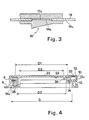
- - la Fig. 3 est une vue de l'ancrage de la garniture élastique ;
- - la Fig. 4 est une vue selon la coupe IV-IV de la Fig. 2 ;
- - la Fig. 5 est une vue d'une variante de réalisation selon l'invention ;
- - la Fig. 6 est une vue de dessous d'une autre variante de réalisation selon l'invention.
- Le regard de chaussée selon l'invention est constitué d'un cadre 1, d'une garniture élastique 2 et d'un tampon 3.
- Le cadre présente une semelle d'appui 4, horizontale, circulaire, de la périphérie intérieure de laquelle part vers le haut une jupe 5 cylindrique délimitant une ouverture circulaire 6 de diamètre intérieur D.
- Le cadre 1 est muni d'un dispositif de verrouillage externe 7 de type connu.
- Dans l'exemple de réalisation représenté Fig. 1, le dispositif de verrouillage externe 7 est une baïonnette. La jupe 5 du cadre présente une saillie externe délimitée par deux faces verticales 8 et 9, de hauteur sensiblement égale à la moitié de celle de la jupe 5, parallèles et à proximité l'une de l'autre, se raccordant sensiblement à angle droit à la moitié supérieure de la jupe 5 du cadre 1, l'arête supérieure de la jupe 5 étant continue avec les arêtes supérieures des faces 8 et 9. Une face verticale 10, de même hauteur que les faces 8 et 9, de longueur L relie les extrémités libres des deux dites faces 8 et 9.
- Cette saillie externe est fermée vers le bas par une face horizontale 11 se raccordant à la jupe 5 du cadre, formant ainsi un logement sensiblement rectangulaire 12. Ce logement 12 est partiellement obturé vers le haut par un couvercle 13, venu de matière avec les faces 8 ou 9 et 10, de longueur au moins égale à L/2, contenu dans le plan horizontal contenant l'arête supérieure de la jupe 5, attenante à une des faces verticales 8 ou 9 et à la moitié de la face verticale 10. La face inférieure 13a du couvercle 13, en regard du logement 12, présente une pente dans le sens tangentiel à la jupe 5, de telle sorte que la section dudit couvercle 13 augmente à mesure que l'on s'approche de la face 8 ou 9 à laquelle il se raccorde.
- La jupe 5 est pourvue d'une collerette intérieure 14, située dans le plan horizontal contenant la face horizontale 11 du dispositif de verrouillage 7 et qui se raccorde à ladite face horizontale 11.
- La collerette intérieure 14 délimite ainsi une ouverture circulaire de diamètre D1 inférieur à D.
- La face inférieure 14a de ladite collerette est pourvue d'au moins une rainure ou un épaulement de section rectangulaire l4b.
- La garniture 2, circulaire, fermée, continue, de forme générale en C, est réalisée en un matériau élastique tel qu'élastomère ou plastomère.
- Elle présente une branche supérieure 15 horizontale, une branche verticale 16 s'étendant vers le bas à partir d'une extrémité de la branche 15, faisant un angle voisin de 90° avec ladite branche 15, et une branche inférieure 17, horizontale, s'étendant sous la branche 15 et faisant un angle voisin de 90° avec la branche verticale 16.
- La longueur des branches supérieure 15 et inférieure 17 est inférieure à la largeur de la collerette 14 du cadre 1. La longueur de la branche verticale 16 est telle que la distance entre les deux faces en vis-à-vis des branches horizontales 15 et 17 soit au maximum égale à l'épaisseur de la collerette 14.
- La face supérieure de la branche 17; en vis-à-vis de la branche 15 est munie d'au moins une languette 17a de section identique à celle de la rainure ou épaulement 14b dont est muni le cadre.
- Ainsi, la garniture 2 peut s'emboîter parfaitement sur la collerette 14 du cadre. La languette 17a venant en coïncidence avec la rainure 14b permet un positionnement idéal.
- La face d'extrémité inférieure 18 de la garniture 2 ainsi constituée présente au moins une pente 19 faisant un angle α avec l'horizontale tel que α est inférieur à 200 et tg α est inférieur à tg φ , tg φ étant le coefficient de frottement entre le matériau dans lequel est réalisée la garniture 2, et celui dans lequel est réalisé le tampon 3.
- La section radiale S de la branche inférieure 17 de la garniture 2 est rectangulaire. Sa hauteur croît ensuite régulièrement sur une longueur l supérieure à la longueur L de la face verticale 10 de la saillie externe dont est muni le cadre, égale à 3 L/2 dans l'exemple de réalisation, puis retrouve brusquement sa hauteur initiale laissant apparaître ainsi une face verticale 20.
- La direction de la ou des pentes 19 est telle que sa section S croît dans le sens de rotation imposé par la baïonnette.
- Il est bien évidemment possible de conjuguer la pente 19 avec une seconde pente dans une direction différente.
- Lorsque la garniture présente plus d'une pente 19, comme on le voit Fig. 2 sur laquelle la garniture présente deux pentes 19, l'angle β entre les deux pentes extrêmes n'excède en aucun cas 120°.
- La garniture 2 délimite une ouverture circulaire de diamètre D2 inférieur à D1.
- Le tampon 3 est constitué d'une plaque circulaire 21 présentant une face supérieure 22 garnie de motifs antidérapants. La face inférieure 23 dudit tampon est munie d'une collerette verticale 24, circulaire, faisant saillie vers le bas, de diamètre intérieur D3 légèrement inférieur au diamètre de l'ouverture délimitée par la garniture 2.
- Le tampon 3 est muni d'une patte radiale 25, rectangulaire, de section trapézoïdale symétrique de celle du couvercle 13 du dispositif de verrouillage du cadre, de faible épaisseur sensiblement égale à la moitié de celle de la plaque 21, en continuité avec la face inférieure 23 de ladite plaque.
- Les dimensions de la patte radiale 25 sont, à la manière connue, telles que lorsque le tampon est placé sur la garniture 2, ladite patte puisse pénétrer dans le logement 12 par l'ouverture 28 ménagée à côté du couvercle 13.
- La collerette 24 du tampon 3 est munie d'au moins une patte d'accrochage 26, rectangulaire, dont la face d'appui supérieure est contenue dans un plan horizontal situé entre le plan contenant la face inférieure 18 de la garniture 2 lorsque la hauteur de la section S est minimale et le plan contenant ladite face inférieure 18 lorsque la section S est maximale.
- Lorsque le tampon ne présente qu'une seule patte d'accrochage 26, celle-ci est de préférence diamètralement opposée à la patte radiale 25.
- Lorsque le tampon présente plus d'une patte d'accrochage 26, l'angle β entre les deux pattes extrêmes ne dépasse pas 120° et les angles γ et γ′ entre chaque patte extrême et la patte radiale 25 sont au minimum égaux à 110°.
- De manière préférentielle, les angles γ et γ′ sont égaux.
- Pour monter le regard de chaussée selon l'invention, il faut se munir d'une garniture ayant le même nombre de pentes 19 que le tampon présente de pattes d'accrochage 26, disposées identiquement.
- La garniture 2 est emboîtée sur la collerette 14 du cadre de telle sorte que lorsque l'on vient placer le tampon en glissant les pattes d'accrochage 26 sous la garniture 2, la patte radiale 25 se trouvant en vis-à-vis de l'orifice ménagé au-dessus du logement 12, chaque patte d'accrochage 26 se trouve sous la garniture 2, en contact avec ladite garniture au niveau du commencement d'une pente 19.
- Pour verrouiller le regard, il suffit de faire passer la patte radiale 25 du tampon sous le couvercle 13 obturant en partie le logement 12, en faisant subir une rotation du tampon jusqu'à obtenir une compression de la branche supérieure 15 de la garniture 2. Ladite patte 25 est alors prisonnière dans le logement 12. Pendant cette rotation, chaque patte d'accrochage 26 coopère avec une pente 19 correspondante de la garniture 2. Le matériau dans lequel est faite la garniture 2 étant élastique, celle-ci est comprimée et écrasée au niveau de la ou des pattes d'accrochage 26. Compte tenu de l'ancrage de la garniture sur la collerette 14 du cadre au moyen du dispositif rainure 14b-languette 17a, celle-ci ne tourne pas avec le tampon.
- Il est possible de supprimer le dernier contact métal-métal en revêtant d'élastomère le logement 12 du dispositif d'accrochage 7.
- Ainsi le regard est verrouillé par au moins deux points de contact. Un tel regard est silencieux et ne se déverrouille pas par accident car la garniture 2 étant comprimée et écrasée au niveau de sa ou de ses pentes 19, le contact entre ladite garniture 2 et sa ou ses pattes d'accrochage 26 du tampon est permanent même lors du passage d'un véhicule entraînant un écrasement de la branche supérieure 15 de la garniture 2.
- Un dispositif complémentaire d'arrêt en rotation du tampon peut être prévu si les conditions d'utilisation sont particulièrement sévères.
- Une variante de réalisation représentée Fig. 5 consiste à remplacer le dispositif de verrouillage externe 7 par un dispositif à crochet interne.
- Le cadre 1 est circulaire, muni d'une semelle d'appui 4, circulaire et horizontale, d'une jupe cylindrique 5 et d'une collerette intérieure 14 identique à celle décrite dans le mode de réalisation préféré.
- La garniture 2 est également identique à celle décrite dans le mode de réalisation préféré.
- Le tampon 3 présente au moins une patte d'accrochage 26 identique à celle décrite dans le mode de réalisation préféré et la patte radiale 25 est remplacée par un crochet amovible 27 permettant de verrouiller le tampon, en coopérant avec les pattes d'accrochage 26, en le faisant passer sous la garniture 2.
- Une telle réalisation permet d'obtenir un regard parfaitement circulaire sans aucun contact métal-métal entre le cadre et le tampon.
- Une seconde variante de réalisation représentée Fig. 6 est composée d'un cadre circulaire 1 dont la jupe 5 est semblable à celle décrite dans le mode de réalisation préféré, aux différences près qu'elle est ovoïde et que l'ouverture délimitée par ladite jupe présente un renflement 29 concave entraînant ainsi une augmentation ponctuelle de son diamètre D1.
- La garniture 2 est semblable à celle décrite dans le mode de réalisation préféré, sauf qu'elle est également ovoïde et qu'elle comprend au moins deux pentes 19, de préférence diamétralement opposées, une des pentes 19 se situant, lorsque la garniture est montée sur le cadre, dans la zone correspondant à la jonction entre la partie circulaire de la jupe 5 et le renflement 29.
- Dans le cas où la garniture présente plus de deux pentes 19, celles-ci obéissent aux conditions d'angles β, γ et γ′ décrites dans le mode de réalisation préféré.
- Le tampon 3 est circulaire et muni d'au moins deux pattes d'accrochage 26 disposées comme les pentes 19 de la garniture de telle sorte que les conditions relatives aux angles et β, γ et γ′ soient remplies, la patte radiale 25 du mode préféré étant remplacée par une patte d'accrochage 26.
- Pour monter le tampon, il suffit de se munir d'une garniture 2 ayant le même nombre de pentes 19 que le tampon comporte de pattes d'accrochage 26, disposées identiquement.
- La garniture 2 est emboîtée sur la collerette 14 et le tampon est placé en glissant la ou les pattes d'accrochage 26 situées dans la zone circulaire de la jupe 5 du cadre sous la garniture 2. La patte d'accrochage 26 restante est alors en regard du renflement 29 de l'ouverture de la jupe 5 du cadre et peut passer sous ladite jupe.
- Le verrouillage du regard s'effectue par rotation du tampon. Pendant cette rotation chaque patte d'accrochage 26 emprunte sa pente 19 respective de la garniture 2 et la comprime.
- Les avantages du regard de chaussée selon l'invention sont les suivants :
- il ne nécessite aucun usinage particulier ;
- il est économique ;
- il présente au plus un seul contact métal-métal entre le cadre et le tampon ;
- il est indéverrouillable par accident ;
- il est silencieux.
Claims (18)
Priority Applications (1)
| Application Number | Priority Date | Filing Date | Title |
|---|---|---|---|
| AT89470018T ATE79658T1 (de) | 1988-09-29 | 1989-09-15 | Schachtabdeckung. |
Applications Claiming Priority (2)
| Application Number | Priority Date | Filing Date | Title |
|---|---|---|---|
| FR8812934A FR2636991B1 (fr) | 1988-09-29 | 1988-09-29 | Regard de chaussee |
| FR8812934 | 1988-09-29 |
Publications (2)
| Publication Number | Publication Date |
|---|---|
| EP0362103A1 true EP0362103A1 (fr) | 1990-04-04 |
| EP0362103B1 EP0362103B1 (fr) | 1992-08-19 |
Family
ID=9370642
Family Applications (1)
| Application Number | Title | Priority Date | Filing Date |
|---|---|---|---|
| EP89470018A Expired - Lifetime EP0362103B1 (fr) | 1988-09-29 | 1989-09-15 | Regard de chaussée |
Country Status (9)
| Country | Link |
|---|---|
| EP (1) | EP0362103B1 (fr) |
| AT (1) | ATE79658T1 (fr) |
| DE (1) | DE68902529T2 (fr) |
| DK (1) | DK473689A (fr) |
| ES (1) | ES2032723T3 (fr) |
| FR (1) | FR2636991B1 (fr) |
| GR (1) | GR3005446T3 (fr) |
| NO (1) | NO893844L (fr) |
| PT (1) | PT91830B (fr) |
Cited By (1)
| Publication number | Priority date | Publication date | Assignee | Title |
|---|---|---|---|---|
| AU2002301962B2 (en) * | 2001-12-06 | 2006-11-16 | Tacron Industries Pty Ltd | Improved Inspection Hatch |
Citations (4)
| Publication number | Priority date | Publication date | Assignee | Title |
|---|---|---|---|---|
| US1417377A (en) * | 1920-06-07 | 1922-05-23 | Morris Bonnevie | Manhole frame and cover |
| FR2153823A5 (fr) * | 1971-09-23 | 1973-05-04 | Pont A Mousson Fond | |
| US4203686A (en) * | 1978-07-17 | 1980-05-20 | Bowman Harold M | Manhole construction |
| GB2102479A (en) * | 1981-07-06 | 1983-02-02 | Pont A Mousson | A man-hole for a road |
-
1988
- 1988-09-29 FR FR8812934A patent/FR2636991B1/fr not_active Expired - Lifetime
-
1989
- 1989-09-15 DE DE8989470018T patent/DE68902529T2/de not_active Expired - Fee Related
- 1989-09-15 ES ES198989470018T patent/ES2032723T3/es not_active Expired - Lifetime
- 1989-09-15 AT AT89470018T patent/ATE79658T1/de not_active IP Right Cessation
- 1989-09-15 EP EP89470018A patent/EP0362103B1/fr not_active Expired - Lifetime
- 1989-09-26 DK DK473689A patent/DK473689A/da not_active Application Discontinuation
- 1989-09-27 NO NO89893844A patent/NO893844L/no unknown
- 1989-09-27 PT PT91830A patent/PT91830B/pt not_active IP Right Cessation
-
1992
- 1992-08-20 GR GR920400698T patent/GR3005446T3/el unknown
Patent Citations (4)
| Publication number | Priority date | Publication date | Assignee | Title |
|---|---|---|---|---|
| US1417377A (en) * | 1920-06-07 | 1922-05-23 | Morris Bonnevie | Manhole frame and cover |
| FR2153823A5 (fr) * | 1971-09-23 | 1973-05-04 | Pont A Mousson Fond | |
| US4203686A (en) * | 1978-07-17 | 1980-05-20 | Bowman Harold M | Manhole construction |
| GB2102479A (en) * | 1981-07-06 | 1983-02-02 | Pont A Mousson | A man-hole for a road |
Cited By (1)
| Publication number | Priority date | Publication date | Assignee | Title |
|---|---|---|---|---|
| AU2002301962B2 (en) * | 2001-12-06 | 2006-11-16 | Tacron Industries Pty Ltd | Improved Inspection Hatch |
Also Published As
| Publication number | Publication date |
|---|---|
| FR2636991A1 (fr) | 1990-03-30 |
| EP0362103B1 (fr) | 1992-08-19 |
| ES2032723T1 (es) | 1993-03-01 |
| NO893844L (no) | 1990-03-30 |
| ATE79658T1 (de) | 1992-09-15 |
| ES2032723T3 (es) | 1993-04-01 |
| PT91830B (pt) | 1995-07-18 |
| DE68902529T2 (de) | 1993-01-21 |
| GR3005446T3 (fr) | 1993-05-24 |
| PT91830A (pt) | 1990-03-30 |
| DK473689A (da) | 1990-03-30 |
| DE68902529D1 (de) | 1992-09-24 |
| DK473689D0 (da) | 1989-09-26 |
| NO893844D0 (no) | 1989-09-27 |
| FR2636991B1 (fr) | 1990-11-30 |
Similar Documents
| Publication | Publication Date | Title |
|---|---|---|
| EP0286562B1 (fr) | Regard de chaussée à charnière en T | |
| EP0660203B1 (fr) | Boíte de montre | |
| FR2785264A1 (fr) | Dispositif de bouchage | |
| BE630298A (fr) | Dispositif de fermeture inviolable d'un récipient | |
| FR2827261A1 (fr) | Dispositif de bouchage et recipient equipe d'un tel dispositif | |
| LU88163A1 (fr) | Dispositif de fermeture à libération automatique pour récipients | |
| WO2018210943A1 (fr) | Appareil de mixage et de melange pour des preparations alimentaires liquides ou pateuses, de type blender, equipe d'un dispositif de verrouillage des couteaux sur le bol | |
| EP0541466B1 (fr) | Bouchon à vis, en matière synthétique, équipé d'une bague d'inviolabilité | |
| EP0533533B1 (fr) | Regard de chaussée à tampon verrouillé | |
| EP0526373B1 (fr) | Assemblage verrouillé de tuyaux avec garniture d'étanchéité composite | |
| EP4026785B1 (fr) | Dispositif de bouchage comprenant un bouchon articulé sur une base | |
| FR2703578A1 (fr) | Charnière pour le montage d'un ensemble siège-couvercle sur une cuvette de cabinet. | |
| EP0362103B1 (fr) | Regard de chaussée | |
| CH650467A5 (fr) | Dispositif de bouchage pour flacon. | |
| FR2549915A1 (fr) | Perfectionnements aux systemes de vissage comprenant un ecrou a embase et aux composants de ces systemes | |
| FR2698614A1 (fr) | Dispositif de bouchage comprenant un bouchon et une ceinture d'inviolabilité. | |
| EP3237974B1 (fr) | Boite de montre etanche | |
| FR2714117A1 (fr) | Perfectionnements aux boîtiers de filtres à liquide pour moteur. | |
| EP1311439B1 (fr) | Bouchon comportant des moyens de blocage de la deformation radiale de la bague d'inviolabilite | |
| EP2536883B1 (fr) | Regard de chaussée et joint d'etanchéité | |
| EP0996952B1 (fr) | Base support pour disque compact | |
| FR2540078A1 (fr) | Fut non metallique rigide perfectionne | |
| FR2709736A1 (fr) | Dispositif témoin d'ouverture pour des bouteilles comportant un bouchon d'obturation. | |
| FR2802987A1 (fr) | Dispositif de fixation rapide, en particulier pour un siege de vehicule automobile | |
| BE1005640A6 (fr) | Vanne a papillon. |
Legal Events
| Date | Code | Title | Description |
|---|---|---|---|
| PUAI | Public reference made under article 153(3) epc to a published international application that has entered the european phase |
Free format text: ORIGINAL CODE: 0009012 |
|
| AK | Designated contracting states |
Kind code of ref document: A1 Designated state(s): AT BE CH DE ES FR GB GR IT LI LU NL SE |
|
| 17P | Request for examination filed |
Effective date: 19900910 |
|
| 17Q | First examination report despatched |
Effective date: 19910607 |
|
| GRAA | (expected) grant |
Free format text: ORIGINAL CODE: 0009210 |
|
| AK | Designated contracting states |
Kind code of ref document: B1 Designated state(s): AT BE CH DE ES FR GB GR IT LI LU NL SE |
|
| REF | Corresponds to: |
Ref document number: 79658 Country of ref document: AT Date of ref document: 19920915 Kind code of ref document: T |
|
| ITF | It: translation for a ep patent filed | ||
| GBT | Gb: translation of ep patent filed (gb section 77(6)(a)/1977) | ||
| REF | Corresponds to: |
Ref document number: 68902529 Country of ref document: DE Date of ref document: 19920924 |
|
| REG | Reference to a national code |
Ref country code: GR Ref legal event code: FG4A Free format text: 3005446 |
|
| REG | Reference to a national code |
Ref country code: ES Ref legal event code: FG2A Ref document number: 2032723 Country of ref document: ES Kind code of ref document: T3 |
|
| PLBE | No opposition filed within time limit |
Free format text: ORIGINAL CODE: 0009261 |
|
| STAA | Information on the status of an ep patent application or granted ep patent |
Free format text: STATUS: NO OPPOSITION FILED WITHIN TIME LIMIT |
|
| PGFP | Annual fee paid to national office [announced via postgrant information from national office to epo] |
Ref country code: SE Payment date: 19930713 Year of fee payment: 5 |
|
| PGFP | Annual fee paid to national office [announced via postgrant information from national office to epo] |
Ref country code: LU Payment date: 19930721 Year of fee payment: 5 |
|
| PGFP | Annual fee paid to national office [announced via postgrant information from national office to epo] |
Ref country code: BE Payment date: 19930803 Year of fee payment: 5 |
|
| 26N | No opposition filed | ||
| PGFP | Annual fee paid to national office [announced via postgrant information from national office to epo] |
Ref country code: GR Payment date: 19930923 Year of fee payment: 5 |
|
| PGFP | Annual fee paid to national office [announced via postgrant information from national office to epo] |
Ref country code: CH Payment date: 19930927 Year of fee payment: 5 |
|
| PGFP | Annual fee paid to national office [announced via postgrant information from national office to epo] |
Ref country code: AT Payment date: 19930928 Year of fee payment: 5 |
|
| PGFP | Annual fee paid to national office [announced via postgrant information from national office to epo] |
Ref country code: NL Payment date: 19930930 Year of fee payment: 5 |
|
| EPTA | Lu: last paid annual fee | ||
| PG25 | Lapsed in a contracting state [announced via postgrant information from national office to epo] |
Ref country code: AT Effective date: 19940915 Ref country code: LU Free format text: LAPSE BECAUSE OF NON-PAYMENT OF DUE FEES Effective date: 19940915 |
|
| PG25 | Lapsed in a contracting state [announced via postgrant information from national office to epo] |
Ref country code: SE Effective date: 19940916 |
|
| PG25 | Lapsed in a contracting state [announced via postgrant information from national office to epo] |
Ref country code: BE Effective date: 19940930 Ref country code: LI Effective date: 19940930 Ref country code: CH Effective date: 19940930 |
|
| EAL | Se: european patent in force in sweden |
Ref document number: 89470018.6 |
|
| BERE | Be: lapsed |
Owner name: S.A. PONT-A-MOUSSON Effective date: 19940930 |
|
| PG25 | Lapsed in a contracting state [announced via postgrant information from national office to epo] |
Ref country code: GR Free format text: THE PATENT HAS BEEN ANNULLED BY A DECISION OF A NATIONAL AUTHORITY Effective date: 19950331 |
|
| PG25 | Lapsed in a contracting state [announced via postgrant information from national office to epo] |
Ref country code: NL Effective date: 19950401 |
|
| NLV4 | Nl: lapsed or anulled due to non-payment of the annual fee | ||
| REG | Reference to a national code |
Ref country code: GR Ref legal event code: MM2A Free format text: 3005446 Ref country code: CH Ref legal event code: PL |
|
| EUG | Se: european patent has lapsed |
Ref document number: 89470018.6 |
|
| PGFP | Annual fee paid to national office [announced via postgrant information from national office to epo] |
Ref country code: GB Payment date: 19960910 Year of fee payment: 8 |
|
| PGFP | Annual fee paid to national office [announced via postgrant information from national office to epo] |
Ref country code: DE Payment date: 19960919 Year of fee payment: 8 |
|
| PG25 | Lapsed in a contracting state [announced via postgrant information from national office to epo] |
Ref country code: GB Free format text: LAPSE BECAUSE OF NON-PAYMENT OF DUE FEES Effective date: 19970915 |
|
| GBPC | Gb: european patent ceased through non-payment of renewal fee |
Effective date: 19970915 |
|
| PG25 | Lapsed in a contracting state [announced via postgrant information from national office to epo] |
Ref country code: DE Free format text: LAPSE BECAUSE OF NON-PAYMENT OF DUE FEES Effective date: 19980603 |
|
| PGFP | Annual fee paid to national office [announced via postgrant information from national office to epo] |
Ref country code: FR Payment date: 20020917 Year of fee payment: 14 |
|
| PG25 | Lapsed in a contracting state [announced via postgrant information from national office to epo] |
Ref country code: FR Free format text: LAPSE BECAUSE OF NON-PAYMENT OF DUE FEES Effective date: 20040528 |
|
| REG | Reference to a national code |
Ref country code: FR Ref legal event code: ST |
|
| PGFP | Annual fee paid to national office [announced via postgrant information from national office to epo] |
Ref country code: IT Payment date: 20080926 Year of fee payment: 20 |
|
| PGFP | Annual fee paid to national office [announced via postgrant information from national office to epo] |
Ref country code: ES Payment date: 20081021 Year of fee payment: 20 |
|
| REG | Reference to a national code |
Ref country code: ES Ref legal event code: FD2A Effective date: 20090916 |
|
| PG25 | Lapsed in a contracting state [announced via postgrant information from national office to epo] |
Ref country code: ES Free format text: LAPSE BECAUSE OF EXPIRATION OF PROTECTION Effective date: 20090916 |