EP0362158A2 - Vibrator zur Anbringung an Drehantrieben für Bohrmaschinen - Google Patents
Vibrator zur Anbringung an Drehantrieben für Bohrmaschinen Download PDFInfo
- Publication number
- EP0362158A2 EP0362158A2 EP89830412A EP89830412A EP0362158A2 EP 0362158 A2 EP0362158 A2 EP 0362158A2 EP 89830412 A EP89830412 A EP 89830412A EP 89830412 A EP89830412 A EP 89830412A EP 0362158 A2 EP0362158 A2 EP 0362158A2
- Authority
- EP
- European Patent Office
- Prior art keywords
- vibrator
- rotary
- splined
- installing
- plate
- Prior art date
- Legal status (The legal status is an assumption and is not a legal conclusion. Google has not performed a legal analysis and makes no representation as to the accuracy of the status listed.)
- Withdrawn
Links
- 238000005553 drilling Methods 0.000 title claims abstract description 17
- 230000035939 shock Effects 0.000 claims abstract description 4
- 239000006096 absorbing agent Substances 0.000 claims abstract description 3
- 239000002689 soil Substances 0.000 description 2
- 239000013013 elastic material Substances 0.000 description 1
- 239000002184 metal Substances 0.000 description 1
Images


Classifications
-
- E—FIXED CONSTRUCTIONS
- E21—EARTH OR ROCK DRILLING; MINING
- E21B—EARTH OR ROCK DRILLING; OBTAINING OIL, GAS, WATER, SOLUBLE OR MELTABLE MATERIALS OR A SLURRY OF MINERALS FROM WELLS
- E21B7/00—Special methods or apparatus for drilling
- E21B7/24—Drilling using vibrating or oscillating means, e.g. out-of-balance masses
-
- E—FIXED CONSTRUCTIONS
- E21—EARTH OR ROCK DRILLING; MINING
- E21B—EARTH OR ROCK DRILLING; OBTAINING OIL, GAS, WATER, SOLUBLE OR MELTABLE MATERIALS OR A SLURRY OF MINERALS FROM WELLS
- E21B7/00—Special methods or apparatus for drilling
- E21B7/20—Driving or forcing casings or pipes into boreholes, e.g. sinking; Simultaneously drilling and casing boreholes
Definitions
- a metal cylindrical liner is driven in the soil to act as an anti-collapsible support, as the earth is removed from inside by the drilling machine.
- the earth is drilled inside a large pipe which becomes the wall of the hole drilled.
- the drilling operation has to be interrupted when the depth reached is the same as that of the liner so that the same can be driven further down by means of a second liner which is fitted and pushed over the first and the drilling operation can continue inside the first liner buried in the soil.
- the wall of the hole drilled consists of a set of superimposed cylindrical liners, suitable for preventing the earth from collapsing, because of its inconsistency, inside the hole.
- Each liner is currently driven in the earth by means of special machines consisting essentially of a bearing trellis supporting a vibrator at a certain height capable of supporting the liner in a perfectly vertical position and of hitting it repeatedly down so as to allow the liner to penetrate gradually in the earth.
- the purpose of this invention is to eliminate all the problems caused by the alternated and repeated use of the above two machines, by designing a vibrator which may be installed directly on the "rotary" of any drilling machine, so that drilling times are minimized considerably.
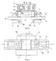
- the device according to the invention includes a vice for gripping the liner at two diametrically opposed points of the edge; the liner being fixed at the bottom to a casing in which the vibrator is housed, consisting of a symmetrical pair of revolving shafts, having the same RPM, on which eccentric masses for creating a vibrating movement are splined.
- This casing is suspended from the fixing flange of the "rotary" of the drill by means of a series of annular rubber pads which act as shock absorbers to prevent the vibrations of the casing from being transmitted to the "rotary".
- the vibrator according to the invention includes a double vice for gripping the edge of a liner, in vertical position, at two diametrically opposed points.
- This double vice consists of two coaxial and opposing hydraulic cylinders (1), each of which is fixed under a respective support block (2) sliding inside a box-shaped guide (3), fixed firmly under a plate (4), which forms the back wall of the casing containing the actual vibrator.
- each hydraulic cylinder (1) on being expelled press on the external edge of the liner, whose internal edge touches a vertical tooth (2a) projecting at the bottom of the sliding block (2).
- the stop position of the sliding block (2) inside the box-shaped guides (3) can be varied so as to adjust the distance of the teeth (2a) which must fit into the edge of the liner, according to the diameter of the liner to be gripped.
- the two box-shaped guides (3) are fixed on diametrically opposite sides, under a plate (4) with a central opening (4a), which closes the casing (5) which contains the vibrator, at the bottom.
- This casing is closed at the top by a counter-plate (6) which must have a wide central opening, like the underlying plate (4), for the passage of the set of rods supporting the drilling tool which digs inside the set of overlying liners driven in the ground.
- An annular platform (7) which is suspended, by means of a number of support and fixing U-bolts (8), at the bottom of the flange (9) fitted outside any "rotary", is fitted over and spaced from the counter-plate (6).
- the counter-plate (6) and the annular platform (7) are connected together by means of an annular series of vertical and opposed pairs of plates (6a and 7a), between which a pad (10) in shock absorbing elastic material, as for example rubber, is fixed so that the annular platform (7) is not affected by the vibrations of the counter-plate (6).
- Two hydraulic motors (11) are fitted outside the two transverse sides of the casing (5) for rotating the respective shafts (12), on each of which a gear (13a) and an eccentric mass (14a) are splined, which creates the vibrating movement of the casing (5), together with another eccentric mass (14b) splined to an intermediate shaft (12a), parallel and fitted next to the main shaft (12), and rotated by the above gear (13a) driven by a geared wheel (13b) splined to the shaft (12a), the gear ratio being equal to one.
Landscapes
- Life Sciences & Earth Sciences (AREA)
- Engineering & Computer Science (AREA)
- Geology (AREA)
- Mining & Mineral Resources (AREA)
- Physics & Mathematics (AREA)
- Environmental & Geological Engineering (AREA)
- Fluid Mechanics (AREA)
- General Life Sciences & Earth Sciences (AREA)
- Geochemistry & Mineralogy (AREA)
- Earth Drilling (AREA)
Applications Claiming Priority (2)
| Application Number | Priority Date | Filing Date | Title |
|---|---|---|---|
| IT62988 | 1988-09-29 | ||
| IT8800629A IT1230812B (it) | 1988-09-29 | 1988-09-29 | Dispositivo vibratore da installare sulle rotary delle macchine trivellatrici |
Publications (2)
| Publication Number | Publication Date |
|---|---|
| EP0362158A2 true EP0362158A2 (de) | 1990-04-04 |
| EP0362158A3 EP0362158A3 (de) | 1991-04-03 |
Family
ID=11293696
Family Applications (1)
| Application Number | Title | Priority Date | Filing Date |
|---|---|---|---|
| EP19890830412 Withdrawn EP0362158A3 (de) | 1988-09-29 | 1989-09-25 | Vibrator zur Anbringung an Drehantrieben für Bohrmaschinen |
Country Status (2)
| Country | Link |
|---|---|
| EP (1) | EP0362158A3 (de) |
| IT (1) | IT1230812B (de) |
Cited By (12)
| Publication number | Priority date | Publication date | Assignee | Title |
|---|---|---|---|---|
| US5263544A (en) * | 1990-01-12 | 1993-11-23 | American Piledriving Equipment, Inc. | Shock absorbing apparatus and method for a vibratory pile driving machine |
| US5544979A (en) * | 1995-03-21 | 1996-08-13 | American Piledriving Equipment, Inc. | Clamp assemblies for driving caissons into the earth |
| US5609380A (en) * | 1994-11-15 | 1997-03-11 | American Piledriving Equipment, Inc. | Clamp assemblies for driving piles into the earth |
| US5653556A (en) * | 1995-10-10 | 1997-08-05 | American Piledriving Equipment, Inc. | Clamping apparatus and methods for driving caissons into the earth |
| US6447036B1 (en) | 1999-03-23 | 2002-09-10 | American Piledriving Equipment, Inc. | Pile clamp systems and methods |
| EP1273411A3 (de) * | 2001-07-05 | 2003-01-15 | Klaus Ertmer Maschinenbautechnologie | Aktivierungsgerät für Schneidköpfe hydraulischer Trägergeräte |
| US9957684B2 (en) | 2015-12-11 | 2018-05-01 | American Piledriving Equipment, Inc. | Systems and methods for installing pile structures in permafrost |
| US10273646B2 (en) | 2015-12-14 | 2019-04-30 | American Piledriving Equipment, Inc. | Guide systems and methods for diesel hammers |
| US10392871B2 (en) | 2015-11-18 | 2019-08-27 | American Piledriving Equipment, Inc. | Earth boring systems and methods with integral debris removal |
| US10538892B2 (en) | 2016-06-30 | 2020-01-21 | American Piledriving Equipment, Inc. | Hydraulic impact hammer systems and methods |
| US12129623B2 (en) | 2021-03-31 | 2024-10-29 | American Piledriving Equipment, Inc. | Segmented ram systems and methods for hydraulic impact hammers |
| US12606972B2 (en) | 2024-02-07 | 2026-04-21 | American Piledriving Equipment, Inc. | Variable moment vibratory systems and methods |
Families Citing this family (2)
| Publication number | Priority date | Publication date | Assignee | Title |
|---|---|---|---|---|
| US9249551B1 (en) | 2012-11-30 | 2016-02-02 | American Piledriving Equipment, Inc. | Concrete sheet pile clamp assemblies and methods and pile driving systems for concrete sheet piles |
| US9371624B2 (en) | 2013-07-05 | 2016-06-21 | American Piledriving Equipment, Inc. | Accessory connection systems and methods for use with helical piledriving systems |
Family Cites Families (3)
| Publication number | Priority date | Publication date | Assignee | Title |
|---|---|---|---|---|
| US3734212A (en) * | 1971-08-20 | 1973-05-22 | Bucyrus Erie Co | Well drill and casing drive unit |
| US3734209A (en) * | 1971-08-20 | 1973-05-22 | Bucyrus Erie Co | Well drilling rod and casing assembling method |
| FR2221948A5 (de) * | 1973-03-12 | 1974-10-11 | Poclain Sa |
-
1988
- 1988-09-29 IT IT8800629A patent/IT1230812B/it active
-
1989
- 1989-09-25 EP EP19890830412 patent/EP0362158A3/de not_active Withdrawn
Cited By (12)
| Publication number | Priority date | Publication date | Assignee | Title |
|---|---|---|---|---|
| US5263544A (en) * | 1990-01-12 | 1993-11-23 | American Piledriving Equipment, Inc. | Shock absorbing apparatus and method for a vibratory pile driving machine |
| US5609380A (en) * | 1994-11-15 | 1997-03-11 | American Piledriving Equipment, Inc. | Clamp assemblies for driving piles into the earth |
| US5544979A (en) * | 1995-03-21 | 1996-08-13 | American Piledriving Equipment, Inc. | Clamp assemblies for driving caissons into the earth |
| US5653556A (en) * | 1995-10-10 | 1997-08-05 | American Piledriving Equipment, Inc. | Clamping apparatus and methods for driving caissons into the earth |
| US6447036B1 (en) | 1999-03-23 | 2002-09-10 | American Piledriving Equipment, Inc. | Pile clamp systems and methods |
| EP1273411A3 (de) * | 2001-07-05 | 2003-01-15 | Klaus Ertmer Maschinenbautechnologie | Aktivierungsgerät für Schneidköpfe hydraulischer Trägergeräte |
| US10392871B2 (en) | 2015-11-18 | 2019-08-27 | American Piledriving Equipment, Inc. | Earth boring systems and methods with integral debris removal |
| US9957684B2 (en) | 2015-12-11 | 2018-05-01 | American Piledriving Equipment, Inc. | Systems and methods for installing pile structures in permafrost |
| US10273646B2 (en) | 2015-12-14 | 2019-04-30 | American Piledriving Equipment, Inc. | Guide systems and methods for diesel hammers |
| US10538892B2 (en) | 2016-06-30 | 2020-01-21 | American Piledriving Equipment, Inc. | Hydraulic impact hammer systems and methods |
| US12129623B2 (en) | 2021-03-31 | 2024-10-29 | American Piledriving Equipment, Inc. | Segmented ram systems and methods for hydraulic impact hammers |
| US12606972B2 (en) | 2024-02-07 | 2026-04-21 | American Piledriving Equipment, Inc. | Variable moment vibratory systems and methods |
Also Published As
| Publication number | Publication date |
|---|---|
| IT8800629A0 (it) | 1988-09-29 |
| EP0362158A3 (de) | 1991-04-03 |
| IT1230812B (it) | 1991-11-07 |
Similar Documents
| Publication | Publication Date | Title |
|---|---|---|
| EP0362158A2 (de) | Vibrator zur Anbringung an Drehantrieben für Bohrmaschinen | |
| US5027908A (en) | Bearing apparatus and method for preloading bearings for rotary-vibratory drills | |
| EP0024748A2 (de) | Vorrichtung und/oder Anwendung im Zusammenhang mit der Erzeugung oder Verwendung von Drücken, Kräften, Strömungen und Bewegungen in oder mittels hydraulischer oder hydro-pneumatischer Systeme | |
| EP1105210A4 (de) | Verstellbarer exzenterschwinghammer | |
| US3477237A (en) | Method of vibrating a member to drive it in a resistive medium | |
| KR102138899B1 (ko) | 진동고무를 포함하는 탈부착 바이브로 함마 및 이를 이용한 천공 및 지반 보강 시공 방법 | |
| CN107842312A (zh) | 一种井下掏槽施工装置 | |
| WO2016102432A1 (de) | Tiefenrüttler | |
| US3349854A (en) | Eccentric vibrator | |
| CN101382039A (zh) | 大直径随钻跟管钻机全液压随钻跟管驱动装置 | |
| EP3384096B1 (de) | Anordnung zur bereitstellung einer pulsierenden druckkraft | |
| RU2206700C1 (ru) | Вибратор | |
| SU683814A1 (ru) | Импульсный вибровозбудитель | |
| DE10232314A1 (de) | Vorrichtung und Verfahren zum Verdichten von Böden und zur Herstellung von säulenförmigen Körpern im Boden mit Hilfe von Tiefenrüttlern | |
| CN220748198U (zh) | 一种环切锤钻孔液压取芯装置 | |
| CN222045697U (zh) | 一种用于灌注桩施工的装置 | |
| US3659464A (en) | Mechanical vibrator | |
| SU901449A1 (ru) | Виброгрейфер | |
| US3344995A (en) | Method and apparatus for disintegrating concrete and like materials | |
| SU1033639A2 (ru) | Дебалансный механизм виброгрейфера | |
| CN1975093B (zh) | 旋振动力头 | |
| SU909044A1 (ru) | Устройство дл образовани скважин в грунте | |
| SU1214901A1 (ru) | Устройство дл образовани котлованов под фундаменты | |
| SU968225A1 (ru) | Устройство дл образовани скважин в грунте | |
| JPH09125359A (ja) | 地盤改良工法 |
Legal Events
| Date | Code | Title | Description |
|---|---|---|---|
| PUAI | Public reference made under article 153(3) epc to a published international application that has entered the european phase |
Free format text: ORIGINAL CODE: 0009012 |
|
| AK | Designated contracting states |
Kind code of ref document: A2 Designated state(s): AT BE CH DE ES FR GB GR LI LU NL SE |
|
| PUAL | Search report despatched |
Free format text: ORIGINAL CODE: 0009013 |
|
| AK | Designated contracting states |
Kind code of ref document: A3 Designated state(s): AT BE CH DE ES FR GB GR LI LU NL SE |
|
| 17P | Request for examination filed |
Effective date: 19910923 |
|
| 17Q | First examination report despatched |
Effective date: 19921123 |
|
| STAA | Information on the status of an ep patent application or granted ep patent |
Free format text: STATUS: THE APPLICATION IS DEEMED TO BE WITHDRAWN |
|
| 18D | Application deemed to be withdrawn |
Effective date: 19931102 |