EP0362165A1 - Verfahren zum Abgeben elektromagnetischer Leistung von einem Antennenelement - Google Patents
Verfahren zum Abgeben elektromagnetischer Leistung von einem Antennenelement Download PDFInfo
- Publication number
- EP0362165A1 EP0362165A1 EP89850199A EP89850199A EP0362165A1 EP 0362165 A1 EP0362165 A1 EP 0362165A1 EP 89850199 A EP89850199 A EP 89850199A EP 89850199 A EP89850199 A EP 89850199A EP 0362165 A1 EP0362165 A1 EP 0362165A1
- Authority
- EP
- European Patent Office
- Prior art keywords
- polarization
- angle
- antenna element
- receiver
- antenna
- Prior art date
- Legal status (The legal status is an assumption and is not a legal conclusion. Google has not performed a legal analysis and makes no representation as to the accuracy of the status listed.)
- Granted
Links
- 238000000034 method Methods 0.000 title claims abstract description 13
- 230000010287 polarization Effects 0.000 claims abstract description 46
- 239000004020 conductor Substances 0.000 claims description 4
- 230000005855 radiation Effects 0.000 claims description 3
- 230000005540 biological transmission Effects 0.000 claims 1
- 230000005672 electromagnetic field Effects 0.000 claims 1
- 230000003321 amplification Effects 0.000 abstract description 2
- 238000003199 nucleic acid amplification method Methods 0.000 abstract description 2
- 239000000306 component Substances 0.000 description 16
- 239000000523 sample Substances 0.000 description 3
- 230000001419 dependent effect Effects 0.000 description 2
- 238000010586 diagram Methods 0.000 description 2
- 230000002238 attenuated effect Effects 0.000 description 1
- 230000003247 decreasing effect Effects 0.000 description 1
- 230000010363 phase shift Effects 0.000 description 1
Images

Classifications
-
- H—ELECTRICITY
- H01—ELECTRIC ELEMENTS
- H01Q—ANTENNAS, i.e. RADIO AERIALS
- H01Q21/00—Antenna arrays or systems
- H01Q21/24—Combinations of antenna units polarised in different directions for transmitting or receiving circularly and elliptically polarised waves or waves linearly polarised in any direction
- H01Q21/245—Combinations of antenna units polarised in different directions for transmitting or receiving circularly and elliptically polarised waves or waves linearly polarised in any direction provided with means for varying the polarisation
-
- H—ELECTRICITY
- H01—ELECTRIC ELEMENTS
- H01Q—ANTENNAS, i.e. RADIO AERIALS
- H01Q3/00—Arrangements for changing or varying the orientation or the shape of the directional pattern of the waves radiated from an antenna or antenna system
- H01Q3/26—Arrangements for changing or varying the orientation or the shape of the directional pattern of the waves radiated from an antenna or antenna system varying the relative phase or relative amplitude of energisation between two or more active radiating elements; varying the distribution of energy across a radiating aperture
Definitions
- the present invention relates to a method of feeding out electromagnetic power in an antenna element or an antenna array including a plurality of antenna elements.
- the method is primarily intended to be utilized in antenna elements mounted on the surface of an airborne vechicle satellite.
- circularly polarized antennas i.e. antennas which transit circularly polarized radiation, and which have a very wide covering area. If the antenna must be mounted on the surface of the aircraft or the satellite, due to aerodynamic requirements, only limited coverage can be achieved by circular polarization, as described, e.g., by R. J. Mailloux "Phased array aircraft antennas for satellite communications", Microwave Journal Oct. 1977, p. 38. The reason is that circular polarization can be regarded as a combination of a vertical and a horizontall polarization with 90 o phase shift.
- the horizontal polarization component of the field which is thus parallel to the surface of the vehicle, will be short-circuited while the vertical polarization component at right angles to the surface is only decreased or attenuated by a certain amount (approximately 3.2 dB).
- a horizontal and a vertical polarization component are respectively defined as components parallel and perpendicular to an electrically conductive surface (the surface of the vehicle).
- the loss in a circular-polarized antenna outside the vehicle will be a further 6 dB, however, of which 3 dB is because only vertical polarization can be seen, and a further 3 dB in the feed network, since both polarization components are fed.
- the object of the present invention is to increase the transmitting power of an antenna mounted on the surface of an airborne vehicle which is fed with circular polarization and for different reception angles in the elevation direction.
- FIG 1 there is illustrated an aircraft surface 1, on which an antenna element is disposed.
- the antenna element can receive or transmit a field with two feed polarizations, the components of which are denoted M1 and M2, where M1 is perpendicular to M2, although both are in the same horizontal plane.
- the feed field from the antenna waveguide is circularly polarized in this case, and the planes of both components are in the same plane as that of the aircraft surface 1.
- Figure 2 is a depiction of the field about a feed polarization component M1. This gives rise to a field about the antenna element 4 which contains a vertical polarization V1 and a horizontal polarization H1. The field is here linearly polarized.
- FIG 3 illustrates the two feed polarizations M1 and M2, which according to Figure 2 each can be divided into a vertical and a horizontal polarization component.
- a circularly polarized feed field can thus be regarded conventionally as two orthogonal polarizations V1, H1 and V2, H2, where the H component is phase-shifted 90 o in relation to the V component.
- Each of the polarizations M1 and M2 can resolve into linearly vertical or horizontal polarization depending on from what azimuth angle ⁇ they are observed.
- the angle of elevation for transmitting to different receivers is denoted by ⁇ in Figure 1. It is obvious that for large elevation angles ⁇ the components H1 and H2 will be short-circuited in the conductive aircraft surface 1.
- FIG. 4 is simplified block diagram of an antenna feed for carrying out the method in accordance with the invention. It comprises a switch means 4, which receives an incoming microwave signal, which is to be fed out to the antenna element 2 and be transmitted to a given receiver.
- the switch means 4 is controlled by a signal giving the values of the angles ⁇ , ⁇ applying to the receiver in question, and according to the conditions set out above.
- the switch means 4 may comprise, for example, a circular wave conductor, two switches and a power divider.
- the circular wave conductor is provided with two probes which are inserted in the wave conductor wall, one probe being displaced at 90 o to the the other.
- the power divider can divide the incoming microwave signal into two waves of equal power when it is switched into the circuit.
- the power divider is switched out of the circuit and the input signal is either connected to one or the other probes depending on the value of the azimuth angle ⁇ , which applies to the receiver in question (as will be seen from below).
- Either M1 or M2 is fed out in response to the azimuth angle ⁇ , and a lineary polarized field is obtained.
- the waveguide 5 can comprise, for example, an extension of the circular waveguide included in the switch means 4.
- the following table states within which azimuth angle interval the different feeds are used: Angular interval ⁇ Angular interval ⁇ Feed component polarization ⁇ 60 o Immaterial M1, M2 190 o circular ⁇ >60 o 45 o ⁇ 135 o M1 225 o ⁇ 305 o linear ⁇ >60 o 305 o ⁇ 360 o ;0 ⁇ 45 o M2 135 o ⁇ 225 o linear
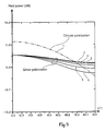
- Figure 5 is a simplified directivity graph for the circularly polarized field, graph 1, and for five different linearly polarized fields, graphs 2,3,4,5 and 6, where the latter are dependent on ten different values of the azimuth angle ⁇ , according to the following:
Landscapes
- Variable-Direction Aerials And Aerial Arrays (AREA)
- Waveguide Aerials (AREA)
Applications Claiming Priority (2)
| Application Number | Priority Date | Filing Date | Title |
|---|---|---|---|
| SE8803418 | 1988-09-27 | ||
| SE8803418A SE462131B (sv) | 1988-09-27 | 1988-09-27 | Foerfarande att utmata elektromagnetisk effekt med olika polarisationer fraan ett antennelement |
Publications (2)
| Publication Number | Publication Date |
|---|---|
| EP0362165A1 true EP0362165A1 (de) | 1990-04-04 |
| EP0362165B1 EP0362165B1 (de) | 1995-05-17 |
Family
ID=20373453
Family Applications (1)
| Application Number | Title | Priority Date | Filing Date |
|---|---|---|---|
| EP89850199A Expired - Lifetime EP0362165B1 (de) | 1988-09-27 | 1989-06-16 | Verfahren zum Abgeben elektromagnetischer Leistung von einem Antennenelement |
Country Status (5)
| Country | Link |
|---|---|
| US (1) | US4947182A (de) |
| EP (1) | EP0362165B1 (de) |
| CA (1) | CA1327075C (de) |
| DE (1) | DE68922682T2 (de) |
| SE (1) | SE462131B (de) |
Cited By (1)
| Publication number | Priority date | Publication date | Assignee | Title |
|---|---|---|---|---|
| CN112290228A (zh) * | 2020-12-29 | 2021-01-29 | 成都信息工程大学 | 一种线-圆极化可重构天线及防雷方法 |
Families Citing this family (2)
| Publication number | Priority date | Publication date | Assignee | Title |
|---|---|---|---|---|
| US7068235B2 (en) * | 2004-07-26 | 2006-06-27 | Row 44, Llc | Antenna system |
| SE543682C2 (en) * | 2020-05-28 | 2021-06-01 | Requtech Ab | Antenna array with cross-polarization leakage suppression |
Citations (4)
| Publication number | Priority date | Publication date | Assignee | Title |
|---|---|---|---|---|
| US3215957A (en) * | 1962-03-05 | 1965-11-02 | Bendix Corp | Variable polarization for microwaves |
| US3938158A (en) * | 1973-12-19 | 1976-02-10 | Raytheon Company | Antenna element for circular or linear polarization |
| US4410891A (en) * | 1979-12-14 | 1983-10-18 | The United States Of America As Represented By The Secretary Of The Army | Microstrip antenna with polarization diversity |
| EP0291233A2 (de) * | 1987-05-11 | 1988-11-17 | Hazeltine Corporation | In die Flugzeughaut integrierte Mehrmoden-Rundumantenne |
Family Cites Families (1)
| Publication number | Priority date | Publication date | Assignee | Title |
|---|---|---|---|---|
| US4051474A (en) * | 1975-02-18 | 1977-09-27 | The United States Of America As Represented By The Secretary Of The Air Force | Interference rejection antenna system |
-
1988
- 1988-09-27 SE SE8803418A patent/SE462131B/sv not_active IP Right Cessation
-
1989
- 1989-06-16 EP EP89850199A patent/EP0362165B1/de not_active Expired - Lifetime
- 1989-06-16 DE DE68922682T patent/DE68922682T2/de not_active Expired - Lifetime
- 1989-07-05 US US07/375,595 patent/US4947182A/en not_active Expired - Lifetime
- 1989-09-22 CA CA000612550A patent/CA1327075C/en not_active Expired - Fee Related
Patent Citations (4)
| Publication number | Priority date | Publication date | Assignee | Title |
|---|---|---|---|---|
| US3215957A (en) * | 1962-03-05 | 1965-11-02 | Bendix Corp | Variable polarization for microwaves |
| US3938158A (en) * | 1973-12-19 | 1976-02-10 | Raytheon Company | Antenna element for circular or linear polarization |
| US4410891A (en) * | 1979-12-14 | 1983-10-18 | The United States Of America As Represented By The Secretary Of The Army | Microstrip antenna with polarization diversity |
| EP0291233A2 (de) * | 1987-05-11 | 1988-11-17 | Hazeltine Corporation | In die Flugzeughaut integrierte Mehrmoden-Rundumantenne |
Cited By (2)
| Publication number | Priority date | Publication date | Assignee | Title |
|---|---|---|---|---|
| CN112290228A (zh) * | 2020-12-29 | 2021-01-29 | 成都信息工程大学 | 一种线-圆极化可重构天线及防雷方法 |
| CN112290228B (zh) * | 2020-12-29 | 2021-03-16 | 成都信息工程大学 | 一种线-圆极化可重构天线的防雷方法 |
Also Published As
| Publication number | Publication date |
|---|---|
| CA1327075C (en) | 1994-02-15 |
| EP0362165B1 (de) | 1995-05-17 |
| US4947182A (en) | 1990-08-07 |
| SE462131B (sv) | 1990-05-07 |
| DE68922682T2 (de) | 1995-10-19 |
| SE8803418L (sv) | 1990-03-28 |
| SE8803418D0 (sv) | 1988-09-27 |
| DE68922682D1 (de) | 1995-06-22 |
Similar Documents
| Publication | Publication Date | Title |
|---|---|---|
| US7436370B2 (en) | Device and method for polarization control for a phased array antenna | |
| US5561434A (en) | Dual band phased array antenna apparatus having compact hardware | |
| CA2217686C (en) | Multi-function interactive communications system with circularly/elliptically polarized signal transmission and reception | |
| DE3934155C2 (de) | Verfahren zum Messen einer Amplitude und einer Phase jedes Antennenelementes einer phasengesteuerten Antennenanordnung sowie Antennenanordnung zum Durchführen des Verfahrens | |
| US4604624A (en) | Phased array antenna employing linear scan for wide-angle arc coverage with polarization matching | |
| US5264862A (en) | High-isolation collocated antenna systems | |
| US5708679A (en) | Hitless ultra small aperture terminal satellite communication network | |
| US7345625B1 (en) | Radar polarization calibration and correction | |
| EP0516440A1 (de) | Mikrostreifenantenne | |
| WO2016004001A1 (en) | Systems and methods for polarization control | |
| EP0735608B1 (de) | Gruppenantennenvorrichtung | |
| US2953786A (en) | Antenna for polarized propagation | |
| CN216288950U (zh) | 天线、信息处理装置以及复合天线装置 | |
| US6542130B2 (en) | Tuneable antenna | |
| US6801789B1 (en) | Multiple-beam antenna | |
| EP0362165A1 (de) | Verfahren zum Abgeben elektromagnetischer Leistung von einem Antennenelement | |
| EP0540124B1 (de) | Antennensystem für Satelliten-Kommunikation | |
| US5355139A (en) | Microstrip antenna system | |
| GB2191044A (en) | Antenna arrangement | |
| Abdel-Wahab et al. | Affordable large scale active-phased array antenna for Ka-band mobile SATCOM applications | |
| Karode et al. | Frequency offset retrodirective antenna array | |
| Itoh et al. | Slot-monopole antenna system for energy-density reception at UHF | |
| EP0169823B1 (de) | Satellitensender-Empfängersystem | |
| KR100539650B1 (ko) | 차량의 위성 및/또는 지상 무선 신호용 수신 안테나 장치 | |
| US2810127A (en) | Turnstile antenna and feed system therefor |
Legal Events
| Date | Code | Title | Description |
|---|---|---|---|
| PUAI | Public reference made under article 153(3) epc to a published international application that has entered the european phase |
Free format text: ORIGINAL CODE: 0009012 |
|
| AK | Designated contracting states |
Kind code of ref document: A1 Designated state(s): CH DE FR GB IT LI NL |
|
| 17P | Request for examination filed |
Effective date: 19900905 |
|
| 17Q | First examination report despatched |
Effective date: 19930204 |
|
| GRAA | (expected) grant |
Free format text: ORIGINAL CODE: 0009210 |
|
| AK | Designated contracting states |
Kind code of ref document: B1 Designated state(s): CH DE FR GB IT LI NL |
|
| ITF | It: translation for a ep patent filed | ||
| REF | Corresponds to: |
Ref document number: 68922682 Country of ref document: DE Date of ref document: 19950622 |
|
| ET | Fr: translation filed | ||
| PLBE | No opposition filed within time limit |
Free format text: ORIGINAL CODE: 0009261 |
|
| STAA | Information on the status of an ep patent application or granted ep patent |
Free format text: STATUS: NO OPPOSITION FILED WITHIN TIME LIMIT |
|
| 26N | No opposition filed | ||
| REG | Reference to a national code |
Ref country code: GB Ref legal event code: IF02 |
|
| PGFP | Annual fee paid to national office [announced via postgrant information from national office to epo] |
Ref country code: FR Payment date: 20020530 Year of fee payment: 14 |
|
| PGFP | Annual fee paid to national office [announced via postgrant information from national office to epo] |
Ref country code: CH Payment date: 20020603 Year of fee payment: 14 |
|
| PGFP | Annual fee paid to national office [announced via postgrant information from national office to epo] |
Ref country code: NL Payment date: 20020610 Year of fee payment: 14 |
|
| PG25 | Lapsed in a contracting state [announced via postgrant information from national office to epo] |
Ref country code: CH Free format text: LAPSE BECAUSE OF NON-PAYMENT OF DUE FEES Effective date: 20030630 Ref country code: LI Free format text: LAPSE BECAUSE OF NON-PAYMENT OF DUE FEES Effective date: 20030630 |
|
| PG25 | Lapsed in a contracting state [announced via postgrant information from national office to epo] |
Ref country code: NL Free format text: LAPSE BECAUSE OF NON-PAYMENT OF DUE FEES Effective date: 20040101 |
|
| REG | Reference to a national code |
Ref country code: CH Ref legal event code: PL |
|
| PG25 | Lapsed in a contracting state [announced via postgrant information from national office to epo] |
Ref country code: FR Free format text: LAPSE BECAUSE OF NON-PAYMENT OF DUE FEES Effective date: 20040227 |
|
| NLV4 | Nl: lapsed or anulled due to non-payment of the annual fee |
Effective date: 20040101 |
|
| REG | Reference to a national code |
Ref country code: FR Ref legal event code: ST |
|
| PG25 | Lapsed in a contracting state [announced via postgrant information from national office to epo] |
Ref country code: IT Free format text: LAPSE BECAUSE OF NON-PAYMENT OF DUE FEES;WARNING: LAPSES OF ITALIAN PATENTS WITH EFFECTIVE DATE BEFORE 2007 MAY HAVE OCCURRED AT ANY TIME BEFORE 2007. THE CORRECT EFFECTIVE DATE MAY BE DIFFERENT FROM THE ONE RECORDED. Effective date: 20050616 |
|
| PGFP | Annual fee paid to national office [announced via postgrant information from national office to epo] |
Ref country code: DE Payment date: 20080731 Year of fee payment: 20 |
|
| PGFP | Annual fee paid to national office [announced via postgrant information from national office to epo] |
Ref country code: GB Payment date: 20080627 Year of fee payment: 20 |
|
| REG | Reference to a national code |
Ref country code: GB Ref legal event code: PE20 Expiry date: 20090615 |
|
| PG25 | Lapsed in a contracting state [announced via postgrant information from national office to epo] |
Ref country code: GB Free format text: LAPSE BECAUSE OF EXPIRATION OF PROTECTION Effective date: 20090615 |