EP0362261B1 - Piston-plongeur refroidissable pour moteurs a combustion interne - Google Patents
Piston-plongeur refroidissable pour moteurs a combustion interne Download PDFInfo
- Publication number
- EP0362261B1 EP0362261B1 EP88904955A EP88904955A EP0362261B1 EP 0362261 B1 EP0362261 B1 EP 0362261B1 EP 88904955 A EP88904955 A EP 88904955A EP 88904955 A EP88904955 A EP 88904955A EP 0362261 B1 EP0362261 B1 EP 0362261B1
- Authority
- EP
- European Patent Office
- Prior art keywords
- piston
- annular wall
- wall support
- cooling oil
- passage portion
- Prior art date
- Legal status (The legal status is an assumption and is not a legal conclusion. Google has not performed a legal analysis and makes no representation as to the accuracy of the status listed.)
- Expired - Lifetime
Links
- 238000002485 combustion reaction Methods 0.000 title claims description 3
- 238000001816 cooling Methods 0.000 claims abstract description 24
- 241001125879 Gobio Species 0.000 claims 2
- 238000002347 injection Methods 0.000 description 2
- 239000007924 injection Substances 0.000 description 2
- 230000001419 dependent effect Effects 0.000 description 1
- 239000007788 liquid Substances 0.000 description 1
- 238000003466 welding Methods 0.000 description 1
Images
Classifications
-
- F—MECHANICAL ENGINEERING; LIGHTING; HEATING; WEAPONS; BLASTING
- F02—COMBUSTION ENGINES; HOT-GAS OR COMBUSTION-PRODUCT ENGINE PLANTS
- F02F—CYLINDERS, PISTONS OR CASINGS, FOR COMBUSTION ENGINES; ARRANGEMENTS OF SEALINGS IN COMBUSTION ENGINES
- F02F3/00—Pistons
- F02F3/16—Pistons having cooling means
- F02F3/20—Pistons having cooling means the means being a fluid flowing through or along piston
- F02F3/22—Pistons having cooling means the means being a fluid flowing through or along piston the fluid being liquid
-
- F—MECHANICAL ENGINEERING; LIGHTING; HEATING; WEAPONS; BLASTING
- F02—COMBUSTION ENGINES; HOT-GAS OR COMBUSTION-PRODUCT ENGINE PLANTS
- F02F—CYLINDERS, PISTONS OR CASINGS, FOR COMBUSTION ENGINES; ARRANGEMENTS OF SEALINGS IN COMBUSTION ENGINES
- F02F3/00—Pistons
- F02F3/0015—Multi-part pistons
- F02F3/0069—Multi-part pistons the crown and skirt being interconnected by the gudgeon pin
-
- F—MECHANICAL ENGINEERING; LIGHTING; HEATING; WEAPONS; BLASTING
- F02—COMBUSTION ENGINES; HOT-GAS OR COMBUSTION-PRODUCT ENGINE PLANTS
- F02B—INTERNAL-COMBUSTION PISTON ENGINES; COMBUSTION ENGINES IN GENERAL
- F02B2275/00—Other engines, components or details, not provided for in other groups of this subclass
- F02B2275/14—Direct injection into combustion chamber
-
- F—MECHANICAL ENGINEERING; LIGHTING; HEATING; WEAPONS; BLASTING
- F02—COMBUSTION ENGINES; HOT-GAS OR COMBUSTION-PRODUCT ENGINE PLANTS
- F02F—CYLINDERS, PISTONS OR CASINGS, FOR COMBUSTION ENGINES; ARRANGEMENTS OF SEALINGS IN COMBUSTION ENGINES
- F02F3/00—Pistons
- F02F3/0015—Multi-part pistons
- F02F3/003—Multi-part pistons the parts being connected by casting, brazing, welding or clamping
- F02F2003/0061—Multi-part pistons the parts being connected by casting, brazing, welding or clamping by welding
-
- Y—GENERAL TAGGING OF NEW TECHNOLOGICAL DEVELOPMENTS; GENERAL TAGGING OF CROSS-SECTIONAL TECHNOLOGIES SPANNING OVER SEVERAL SECTIONS OF THE IPC; TECHNICAL SUBJECTS COVERED BY FORMER USPC CROSS-REFERENCE ART COLLECTIONS [XRACs] AND DIGESTS
- Y02—TECHNOLOGIES OR APPLICATIONS FOR MITIGATION OR ADAPTATION AGAINST CLIMATE CHANGE
- Y02T—CLIMATE CHANGE MITIGATION TECHNOLOGIES RELATED TO TRANSPORTATION
- Y02T10/00—Road transport of goods or passengers
- Y02T10/10—Internal combustion engine [ICE] based vehicles
- Y02T10/12—Improving ICE efficiencies
Definitions
- the invention relates to a coolable plunger for internal combustion engines according to the preamble of claim 1.
- Such pistons are e.g. known from US-PS 41 80 027. That known piston is cooled in the region of the piston crown both in the outer annular space and in the radially central inner region.
- the cooling oil is injected from the crank chamber into the outer annulus in the upper part of the piston.
- the cooling oil can penetrate into the area within the inner ring wall support through liquid catch pockets provided at the upper end of the piston skirt.
- GB-A 21 48 451 shows a similar piston.
- the cooling oil intended for the area within the inner ring wall support can also be introduced there only via an external closed cooling channel.
- the cooling oil shaken in the outer cooling channel reaches the piston bottom center through the inertial forces acting on the cooling oil located in the cooling channel during the oscillating movement of the piston through at least one radial opening in the inner ring wall support.
- a direct injection from the crank chamber is not possible so that only preheated cooling oil can reach the center of the piston crown.
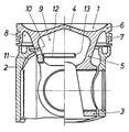
- the piston consists of an upper piston part 1 and a shaft 2, these parts being connected to one another only via a piston pin, not shown.
- the piston pin (not shown) is mounted in the upper piston part 1 in bores of the hubs 3.
- the hubs 3 are connected to the piston crown 4 of the upper piston part via an inner ring wall support 5. Radially on the outside, the piston crown 4 merges into an outer ring wall section 6, which receives the ring grooves 7.
- Cooling oil is injected into the outer annular space 8 from the crank chamber in a manner not shown.
- a radial opening 10 is provided in the ring wall support.
- a channel section 11, which is open toward the piston axis, is formed from the inner surface of the piston skirt 2.
- the direction of flow in this channel lies in a radial plane spanned by the piston axis and is curved in such a way that the end of the channel section facing the piston head opens directly into the opening 10.
- the curvature of the flow channel in the channel section 11 is selected such that the oil injected from the crank chamber through a nozzle in the form of an oil jet opens approximately tangentially into the channel section 11.
- the size of the channel cross-section is chosen so that it is somewhat smaller is the opening cross-section of the radial opening 10. In this way, a complete transfer of the cooling oil from the channel into the opening 10 is ensured.
- the interior 9 is closed at its downward open end by a e.g. closed cover 12 inserted by screws or welding.
- a e.g. closed cover 12 inserted by screws or welding.
- cover 12 represents only a bridge-like structure partially covering the lower opening of the interior 9, the edges which do not directly adjoin the ring wall support can be designed as a collar 13.
Landscapes
- Engineering & Computer Science (AREA)
- Chemical & Material Sciences (AREA)
- Combustion & Propulsion (AREA)
- Mechanical Engineering (AREA)
- General Engineering & Computer Science (AREA)
- Physics & Mathematics (AREA)
- Fluid Mechanics (AREA)
- Pistons, Piston Rings, And Cylinders (AREA)
Abstract
Claims (3)
Applications Claiming Priority (2)
| Application Number | Priority Date | Filing Date | Title |
|---|---|---|---|
| DE19873717767 DE3717767A1 (de) | 1987-05-26 | 1987-05-26 | Kuehlbarer tauchkolben fuer verbrennungsmotoren |
| DE3717767 | 1987-05-26 |
Publications (2)
| Publication Number | Publication Date |
|---|---|
| EP0362261A1 EP0362261A1 (fr) | 1990-04-11 |
| EP0362261B1 true EP0362261B1 (fr) | 1991-05-22 |
Family
ID=6328476
Family Applications (1)
| Application Number | Title | Priority Date | Filing Date |
|---|---|---|---|
| EP88904955A Expired - Lifetime EP0362261B1 (fr) | 1987-05-26 | 1988-05-21 | Piston-plongeur refroidissable pour moteurs a combustion interne |
Country Status (7)
| Country | Link |
|---|---|
| US (1) | US4947805A (fr) |
| EP (1) | EP0362261B1 (fr) |
| JP (1) | JP2588959B2 (fr) |
| AU (1) | AU1931988A (fr) |
| BR (1) | BR8807519A (fr) |
| DE (2) | DE3717767A1 (fr) |
| WO (1) | WO1988009433A1 (fr) |
Families Citing this family (14)
| Publication number | Priority date | Publication date | Assignee | Title |
|---|---|---|---|---|
| DE3732927A1 (de) * | 1987-09-30 | 1989-04-13 | Mahle Gmbh | Kuehlbarer tauchkolben fuer verbrennungsmotoren |
| DE4010062A1 (de) * | 1990-03-29 | 1991-10-02 | Mahle Gmbh | Gekuehlter tauchkolben fuer verbrennungsmotoren mit voneinander getrenntem kolbenoberteil und kolbenschaft |
| DE4014705C2 (de) * | 1990-05-08 | 1999-06-10 | Mahle Gmbh | Gekühlter Tauchkolben für Verbrennungsmotoren mit voneinander getrenntem Kolbenoberteil und Kolbenschaft |
| DE4108650C2 (de) * | 1990-05-08 | 1999-04-15 | Mahle Gmbh | Gekühlter Tauchkolben für Verbrennungsmotoren mit voneinander getrenntem Kolbenoberteil und Kolbenschaft |
| DE4014703A1 (de) * | 1990-05-08 | 1991-11-14 | Mahle Gmbh | Gekuehlter tauchkolben fuer verbrennungsmotoren mit voneinander getrenntem kolbenoberteil und kolbenschaft |
| IT1240526B (it) * | 1990-07-31 | 1993-12-17 | Borgo Nova S.P.A. | Perfezionamento relativo a pistoni, in genere. |
| US5692430A (en) * | 1995-06-08 | 1997-12-02 | Caterpillar Inc. | Articulated piston apparatus including a cooling gallery |
| DE19747944A1 (de) | 1997-10-30 | 1999-05-06 | Mahle Gmbh | Kolben mit zentralem Kühlraum |
| WO2001073275A1 (fr) | 2000-03-28 | 2001-10-04 | Federal-Mogul Corporation | Piston à grande puissance pourvu d'un déflecteur d'huile |
| DE10257022A1 (de) * | 2002-12-06 | 2004-06-17 | Mahle Gmbh | Mehrteiliger gekühlter Kolben für einen Verbrennungsmotor |
| DE10322921A1 (de) * | 2003-05-21 | 2004-12-16 | Mahle Gmbh | Verfahren zur Herstellung eines einteiligen Kolbens für einen Verbrennungsmotor |
| DE102009045437A1 (de) * | 2009-10-07 | 2011-04-14 | Federal-Mogul Nürnberg GmbH | Kolben für einen Verbrennungsmotor und Verbrennungsmotor mit einem Kolben |
| CN103362682B (zh) * | 2013-08-06 | 2015-08-26 | 安徽江淮汽车股份有限公司 | 一种柴油发动机活塞 |
| DE102013013962A1 (de) * | 2013-08-23 | 2015-02-26 | Mahle International Gmbh | Baueinheit aus einem Kolben und einer Anspritzdüse für einen Verbrennungsmotor |
Family Cites Families (6)
| Publication number | Priority date | Publication date | Assignee | Title |
|---|---|---|---|---|
| DE2543478C2 (de) * | 1975-09-30 | 1983-01-05 | Günter 8543 Hilpoltstein Elsbett | Kolben für Brennkraftmaschinen, insb. Dieselmotoren |
| US4056044A (en) * | 1975-11-12 | 1977-11-01 | Caterpillar Tractor Co. | Oil cooled piston |
| US4377967A (en) * | 1981-03-27 | 1983-03-29 | Mack Trucks, Inc. | Two-piece piston assembly |
| DE3210771A1 (de) * | 1982-03-24 | 1983-09-29 | Günter 8543 Hilpoltstein Elsbett | Kolbentrieb fuer hubkolben-brennkraftmaschinen, wie dieselmotoren u.a. |
| DE3338419A1 (de) * | 1983-10-22 | 1985-05-02 | Mtu Motoren- Und Turbinen-Union Friedrichshafen Gmbh, 7990 Friedrichshafen | Kolben fuer eine hubkolbenbrennkraftmaschine |
| DE3425228A1 (de) * | 1984-07-09 | 1986-02-06 | Klöckner-Humboldt-Deutz AG, 5000 Köln | Zylinderrohrkuehlung |
-
1987
- 1987-05-26 DE DE19873717767 patent/DE3717767A1/de not_active Withdrawn
-
1988
- 1988-05-21 DE DE8888904955T patent/DE3862936D1/de not_active Expired - Lifetime
- 1988-05-21 EP EP88904955A patent/EP0362261B1/fr not_active Expired - Lifetime
- 1988-05-21 BR BR888807519A patent/BR8807519A/pt not_active IP Right Cessation
- 1988-05-21 JP JP63504699A patent/JP2588959B2/ja not_active Expired - Lifetime
- 1988-05-21 WO PCT/EP1988/000455 patent/WO1988009433A1/fr not_active Ceased
- 1988-05-21 US US07/411,483 patent/US4947805A/en not_active Expired - Lifetime
- 1988-05-21 AU AU19319/88A patent/AU1931988A/en not_active Withdrawn
Also Published As
| Publication number | Publication date |
|---|---|
| WO1988009433A1 (fr) | 1988-12-01 |
| DE3862936D1 (de) | 1991-06-27 |
| AU1931988A (en) | 1988-12-21 |
| DE3717767A1 (de) | 1988-12-08 |
| EP0362261A1 (fr) | 1990-04-11 |
| JPH02503586A (ja) | 1990-10-25 |
| BR8807519A (pt) | 1990-05-22 |
| JP2588959B2 (ja) | 1997-03-12 |
| US4947805A (en) | 1990-08-14 |
Similar Documents
| Publication | Publication Date | Title |
|---|---|---|
| EP0362261B1 (fr) | Piston-plongeur refroidissable pour moteurs a combustion interne | |
| EP0334855B1 (fr) | Piston-fourreau refroidissable pour moteurs a combustion interne | |
| DE69101170T2 (de) | Konstruktion einer Brennkammer für eine Brennkraftmaschine. | |
| EP1185774B1 (fr) | Piston refroidi pour moteurs a combustion interne | |
| EP0731877B1 (fr) | Moteur a combustion interne | |
| DE60121308T2 (de) | Hochleistungskolben mit öldeflektor | |
| EP1963655A1 (fr) | Piston pour moteur a combustion interne et procede de fabrication dudit piston | |
| DE112007001562T5 (de) | Kühlmittelkanalventilationsbaugruppe für einen Kolben | |
| EP0359932B1 (fr) | Piston refroidi par huile pour moteurs à combustion interne | |
| DE10221561A1 (de) | Gekühlter Kolben für einen Verbrennungsmotor | |
| DE3732925C1 (de) | Gekuehlter Tauchkolben fuer Verbrennungsmotoren | |
| EP0855499B1 (fr) | Piston refroidi par un liquide | |
| DE4007992C2 (fr) | ||
| DE3838349C2 (fr) | ||
| DE4030951B4 (de) | Schweröl-Kraftstoffeinspritzeinrichtung für Einspritzbrennkraftmaschinen | |
| DE804048C (de) | Kolben | |
| DE3702694C1 (en) | Oil-cooled piston for internal combustion engines, especially for diesel engines | |
| DE3806749A1 (de) | Verbrennungsmotor sowie diesbezuegliche kolbenanordnung | |
| EP1355057A2 (fr) | Dispositif pour la recirculation des gaz d'échappement d'un moteur à combustion interne | |
| EP0237853B1 (fr) | Piston à éléments multiples pour moteurs à combustion interne | |
| DE3732927C2 (fr) | ||
| DE69202959T2 (de) | Zweitaktbrennkraftmaschine. | |
| DE4221240C2 (de) | Gekühlter zweiteiliger Kolben | |
| EP0206125B1 (fr) | Culasse pour moteur à combustion interne à refroidissement par liquide | |
| DE3834852A1 (de) | Gekuehlter zweiteiliger tauchkolben |
Legal Events
| Date | Code | Title | Description |
|---|---|---|---|
| PUAI | Public reference made under article 153(3) epc to a published international application that has entered the european phase |
Free format text: ORIGINAL CODE: 0009012 |
|
| 17P | Request for examination filed |
Effective date: 19890823 |
|
| AK | Designated contracting states |
Kind code of ref document: A1 Designated state(s): DE FR GB IT SE |
|
| 17Q | First examination report despatched |
Effective date: 19901114 |
|
| GRAA | (expected) grant |
Free format text: ORIGINAL CODE: 0009210 |
|
| AK | Designated contracting states |
Kind code of ref document: B1 Designated state(s): DE FR GB IT SE |
|
| ITF | It: translation for a ep patent filed | ||
| ET | Fr: translation filed | ||
| GBT | Gb: translation of ep patent filed (gb section 77(6)(a)/1977) | ||
| REF | Corresponds to: |
Ref document number: 3862936 Country of ref document: DE Date of ref document: 19910627 |
|
| PLBE | No opposition filed within time limit |
Free format text: ORIGINAL CODE: 0009261 |
|
| STAA | Information on the status of an ep patent application or granted ep patent |
Free format text: STATUS: NO OPPOSITION FILED WITHIN TIME LIMIT |
|
| 26N | No opposition filed | ||
| EAL | Se: european patent in force in sweden |
Ref document number: 88904955.7 |
|
| REG | Reference to a national code |
Ref country code: GB Ref legal event code: IF02 |
|
| PGFP | Annual fee paid to national office [announced via postgrant information from national office to epo] |
Ref country code: SE Payment date: 20070521 Year of fee payment: 20 |
|
| PGFP | Annual fee paid to national office [announced via postgrant information from national office to epo] |
Ref country code: DE Payment date: 20070629 Year of fee payment: 20 |
|
| PGFP | Annual fee paid to national office [announced via postgrant information from national office to epo] |
Ref country code: GB Payment date: 20070419 Year of fee payment: 20 |
|
| PGFP | Annual fee paid to national office [announced via postgrant information from national office to epo] |
Ref country code: IT Payment date: 20070524 Year of fee payment: 20 |
|
| PGFP | Annual fee paid to national office [announced via postgrant information from national office to epo] |
Ref country code: FR Payment date: 20070518 Year of fee payment: 20 |
|
| REG | Reference to a national code |
Ref country code: GB Ref legal event code: PE20 Expiry date: 20080520 |
|
| EUG | Se: european patent has lapsed | ||
| PG25 | Lapsed in a contracting state [announced via postgrant information from national office to epo] |
Ref country code: GB Free format text: LAPSE BECAUSE OF EXPIRATION OF PROTECTION Effective date: 20080520 |