EP0362504B1 - Charnière - Google Patents
Charnière Download PDFInfo
- Publication number
- EP0362504B1 EP0362504B1 EP89113855A EP89113855A EP0362504B1 EP 0362504 B1 EP0362504 B1 EP 0362504B1 EP 89113855 A EP89113855 A EP 89113855A EP 89113855 A EP89113855 A EP 89113855A EP 0362504 B1 EP0362504 B1 EP 0362504B1
- Authority
- EP
- European Patent Office
- Prior art keywords
- hinge
- roll
- angle
- leaf
- stop
- Prior art date
- Legal status (The legal status is an assumption and is not a legal conclusion. Google has not performed a legal analysis and makes no representation as to the accuracy of the status listed.)
- Expired - Lifetime
Links
- 239000000463 material Substances 0.000 description 5
- 101001017827 Mus musculus Leucine-rich repeat flightless-interacting protein 1 Proteins 0.000 description 2
- 238000003780 insertion Methods 0.000 description 2
- 230000037431 insertion Effects 0.000 description 2
- 238000000034 method Methods 0.000 description 2
- 239000002023 wood Substances 0.000 description 2
Images

Classifications
-
- E—FIXED CONSTRUCTIONS
- E05—LOCKS; KEYS; WINDOW OR DOOR FITTINGS; SAFES
- E05D—HINGES OR SUSPENSION DEVICES FOR DOORS, WINDOWS OR WINGS
- E05D11/00—Additional features or accessories of hinges
- E05D11/06—Devices for limiting the opening movement of hinges
-
- E—FIXED CONSTRUCTIONS
- E05—LOCKS; KEYS; WINDOW OR DOOR FITTINGS; SAFES
- E05D—HINGES OR SUSPENSION DEVICES FOR DOORS, WINDOWS OR WINGS
- E05D7/00—Hinges or pivots of special construction
- E05D7/009—Elongate hinges, e.g. piano-hinges
Definitions
- the invention relates to a hinge with two hinge tabs, which are connected at the abutting edges to form a hinge joint made of intermeshing rollers and interspersed with a hinge wire, with devices for fastening to parts of a stop material and with detents for mutual support at an adjustable hinge angle.
- Hinges of the aforementioned type serve, inter alia, for the pivotable fastening of a lid to a lower part of a container-like stop material, for example a box, case or a box made of wood, cardboard or plastic.
- a container-like stop material for example a box, case or a box made of wood, cardboard or plastic.
- One hinge flap is attached to the lid and the other hinge flap is attached to the lower part.
- the hinge tabs have the devices for fastening.
- the detents are provided in order to limit the angle by which the cover can be pivoted relative to the lower part after the hinge has been attached.
- Hinges with a so-called inner stop are known from US-A-4 206 532, i.e. Hinges where the swivel angle of the hinge is limited inwards.
- the inner stop is formed from opposite edge parts on the hinge tabs in pairs.
- the edge part In one of the hinges (FIGS. 1 and 2) the edge part, a projection to be bent to the roll and a recess for receiving the roll of the other hinge flap follow one another cyclically in its axial direction; on the other hinge tab the edge part, a recess for receiving the role of the one hinge tab and a projection to be bent to the role.
- FR-A-942 729 discloses hinges with a so-called external stop, ie hinges in which the pivoting angle of the hinge is limited to the outside.
- the hinge stop is formed by engaging in partially cylindrical recesses on the central roller, which belongs to the hinge tab of one hinge half, of partially cylindrical projections on outer rollers, which belong to the hinge tab of the other hinge half.
- the invention has for its object to provide a hinge which is provided both with an inner stop and with an outer stop, so that it - both for reasons to be described - can be fixed inwards in the later closed position of the stop material and not outwards can be pivoted beyond a certain angle, it is simply constructed.
- this object is achieved in that a lock is provided on each of the hinge tabs, via which the hinge tab is limited in its inward movement to an angle of approximately 180 ° to the other hinge tab - so-called.
- Inner stop - as also a locking mechanism by means of which the hinge flap is limited in its outward movement to an angle of approximately 270 ° to the other hinge flap - so-called external stop.
- Hinges can be attached individually to container-like slings. To rationalize the fastening process, however, it is also known to combine the hinges into band-shaped workpieces. These are then in the form of a strip or — because of the possible large number of hinges per strip-shaped workpiece — preferably in the form of a roll in which the workpiece is rolled up layer by layer in a spiral. The band-shaped workpieces are then gradually moved by means of a feed fed to a sling machine in which the hinges are cut off at the same time - isolated - and attached to the lid and lower part of the box-shaped sling.
- stop tools are necessary which bring the hinges into the later closed position immediately before the stop process, in which the hinge flaps one Form an angle of approx. 180 °, hold there and guide.
- Stop tools known from DE-U-86 00 009 are complex since they require special wall and / or guide devices.
- the hinge tabs are pivoted against each other in a direction up to a position in which they form an angle of 180 °.
- the lock acts in the form of the inner stop. It is the stop position, that is, the position in which the hinge on the lid and lower part of the box-shaped container can be attached most easily. After striking, this is the position in which the lid closes the lower part.
- the provided in the invention - additional - locking in the form of the outer stop causes one Hinge lobe is limited in its outward movement to an angle of approximately 270 ° to the other hinge lobe. As a result, the pivoting movement of the lid is limited to 90 ° in relation to its closed position.
- the hinge designed according to the invention is therefore both simplified in its processing and not restricted in its mode of operation: inner stop and outer stop are realized on the same hinge.
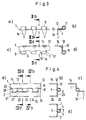
- the hinges chosen as the exemplary embodiment consist of two hinge tabs 1 and 2.
- the hinge tabs 1, 2 are designed as rollers 11, 21 on the inner longitudinal edges facing one another.
- the rollers 11, 21 intermesh like a comb and form a hinge roller 3.
- the hinge roller 3 is penetrated by a hinge wire 4.
- the hinge roller 3 forms a hinge joint with the hinge wire 4.
- Each hinge flap 1, 2 is provided on its edge 12, 22 with insertion tips 14, 24 which are angled essentially at right angles to its flat part 13, 23. Instead of the insertion tips, other devices can be provided for fastening the hinge to parts of an impact material.
- a lock 5 is provided on at least one of the hinge tabs 1, 2. Via the locking mechanism 5, one hinge flap 1 is limited in its inward movement to an angle of 180 ° to the other hinge flap 2; the lock forms a so-called inner stop.
- the lock 5 is provided on each of the hinge tabs 1, 2.
- each roller 11, 21 is provided with a recess 15, 25 on at least one end face.
- the recess 15, 25 is so large that only a remainder 16, 26 remains in the associated roll 11, 21, which essentially has the thickness of the hinge wire 4.
- Each roller 11, 21 has the recess 15, 25 on the same end face.
- the hinge is only provided with an inner stop.
- a further locking device 6 is provided, by means of which this hinge tab 1 limits its outward movement to an angle of 270 ° to the other hinge tab 2 is so-called outside stop.
- the locking device 6 is provided on each hinge tab 1, 2.
- each roller 11, 21 is extended on one end face in the manner of a partial cylinder jacket 17, 27.
- the partial cylinder jacket 17, 27 extends in the circumferential direction from the free edge of the roller 11, 21 to approximately the center of the hinge wire 4.
- Each roller 11, 21 of each hinge tab 1, 2 has the extension on the same end face.
- the hinge is used for the pivotable attachment of a lid to a lower part of a container-like stop material, e.g. a box, case or box made of wood, cardboard or plastic.
Landscapes
- Engineering & Computer Science (AREA)
- Mechanical Engineering (AREA)
- Cartons (AREA)
- Closures For Containers (AREA)
- Rigid Containers With Two Or More Constituent Elements (AREA)
- Hinges (AREA)
Claims (5)
- Charnière avec deux pattes de charnière (1; 2) qui, reliées aux bords contigus en une articulation à charnière constituée de rouleaux (3) qui s'emboîtent à la manière d'un peigne et sont traversés par une cheville de charnière (4), sont munies de dispositifs pour la fixation sur des éléments d'un produit récepteur et de dispositifs d'arrêt pour le soutien réciproque avec un angle de charnière réglable, caractérisée en ce que sur chaque patte de charnière (1; 2) sont prévus aussi bien un dispositif d'arrêt (5) par lequel le mouvement vers l'intérieur de la patte de charnière (1) par rapport à l'autre patte de charnière (2; 1) est limité à un angle d'environ 180° - arrêt dit intérieur - qu'un dispositif d'arrêt (6) par lequel le mouvement vers l'extérieur de la patte de charnière (1; 2) par rapport à l'autre patte de charnière (2; 1) est limité à un angle d'environ 270° - arrêt dit extérieur -.
- Charnière selon la revendication 1, caractérisée en ce que dans la direction axiale, l'une des faces frontales du rouleau (11; 21) est évidée jusqu'à un reste qui est sensiblement égal à l'épaisseur de la cheville de charnière (4).
- Charnière selon la revendication 2, caractérisée en ce que chaque rouleau (11; 21) de chaque patte de charnière (1; 2) présente sur la face frontale l'évidement (15; 25).
- Patte de charnière selon la revendication 1, caractérisée en ce que, dans la direction axiale, le rouleau (11; 21) est prolongé à l'une des faces frontales à la manière d'un corps de cylindre partiel (17; 27), ledit corps de cylindre partiel s'étendant, dans la direction circonférentielle, du bord libre du rouleau (11; 21) jusqu'au milieu environ de la cheville de charnière (4).
- Charnière selon la revendication 4, caractérisé en ce que chaque rouleau (11; 21) de chaque patte de charnière (1; 2) présente le corps de cylindre partiel (17; 27) sur la même face frontale.
Applications Claiming Priority (2)
| Application Number | Priority Date | Filing Date | Title |
|---|---|---|---|
| DE8812459U DE8812459U1 (de) | 1988-10-03 | 1988-10-03 | Scharnier |
| DE8812459U | 1988-10-03 |
Publications (2)
| Publication Number | Publication Date |
|---|---|
| EP0362504A1 EP0362504A1 (fr) | 1990-04-11 |
| EP0362504B1 true EP0362504B1 (fr) | 1993-03-10 |
Family
ID=6828521
Family Applications (1)
| Application Number | Title | Priority Date | Filing Date |
|---|---|---|---|
| EP89113855A Expired - Lifetime EP0362504B1 (fr) | 1988-10-03 | 1989-07-27 | Charnière |
Country Status (3)
| Country | Link |
|---|---|
| EP (1) | EP0362504B1 (fr) |
| DE (2) | DE8812459U1 (fr) |
| ES (1) | ES2040421T3 (fr) |
Families Citing this family (3)
| Publication number | Priority date | Publication date | Assignee | Title |
|---|---|---|---|---|
| DE29618844U1 (de) * | 1996-10-29 | 1997-03-20 | Bosch-Siemens Hausgeräte GmbH, 81669 München | Einbau-Kältegerät |
| DE20014612U1 (de) * | 2000-08-23 | 2000-11-30 | Schmale GmbH & Co KG, 58511 Lüdenscheid | Scharnier |
| DE102004049554B4 (de) * | 2004-10-12 | 2010-04-22 | Edscha Ag | Türscharnier für ein Kraftfahrzeug |
Family Cites Families (2)
| Publication number | Priority date | Publication date | Assignee | Title |
|---|---|---|---|---|
| FR942729A (fr) * | 1947-03-07 | 1949-02-16 | Dispositif limiteur de course pour portes et fenêtres | |
| US4206532A (en) * | 1977-01-28 | 1980-06-10 | Delorenzo Mario M | Hinge construction |
-
1988
- 1988-10-03 DE DE8812459U patent/DE8812459U1/de not_active Expired - Lifetime
-
1989
- 1989-07-27 ES ES198989113855T patent/ES2040421T3/es not_active Expired - Lifetime
- 1989-07-27 DE DE8989113855T patent/DE58903716D1/de not_active Expired - Fee Related
- 1989-07-27 EP EP89113855A patent/EP0362504B1/fr not_active Expired - Lifetime
Also Published As
| Publication number | Publication date |
|---|---|
| DE8812459U1 (de) | 1990-02-08 |
| EP0362504A1 (fr) | 1990-04-11 |
| DE58903716D1 (de) | 1993-04-15 |
| ES2040421T3 (es) | 1993-10-16 |
Similar Documents
| Publication | Publication Date | Title |
|---|---|---|
| DE2920843A1 (de) | Vorrichtung zur befestigung eines tuer- oder fensterbandes an einer zarge | |
| DE202018106418U1 (de) | Kantenschutzelement | |
| EP1740470A2 (fr) | Boite pliante a soufflets pliants | |
| EP0362504A1 (fr) | Charnière | |
| EP0466848B1 (fr) | Charniere pour cadre de tableau | |
| DE2160563A1 (de) | Schlosskasten zur aufnahme von einsteckschloessern | |
| DE2936603C2 (fr) | ||
| DE2356057A1 (de) | Werkzeugkasten mit mehreren verbundenen, seitlich ausbreitbaren faechern | |
| EP0289821B1 (fr) | Charnière à ressort | |
| EP0898636B1 (fr) | Porte a ventail pouvant tre monte de facon a venir buter, au choix, a gauche ou a droite | |
| DE2912717A1 (de) | Schachtel mit verschliessbarer ausschuettoeffnung | |
| DE3627034A1 (de) | Vorrichtung zur befestigung eines beschlags an einem anschlaggut | |
| DE3204933C2 (de) | Geldkassette mit Zähleinsatz | |
| DE29509037U1 (de) | Seitenkantenschutz | |
| DE8802899U1 (de) | Federscharnier | |
| DE2422128B2 (de) | Verschlußoberteil und/oder Verschlußunterteil für kastenförmige Behälter | |
| DE9112323U1 (de) | Eckenschutz-Erzeugnis | |
| EP2277792B1 (fr) | Fermeture | |
| DE7616729U1 (de) | Schachtel mit verborgenem Scharnier | |
| EP0113449B1 (fr) | Pièce à usiner des charnières en forme de bande | |
| DE3807665C1 (en) | Steel cabinet | |
| DE9405322U1 (de) | Packschachtel | |
| DE8706469U1 (de) | Federscharnier | |
| DE60202963T2 (de) | Vorrichtung zum diebstahlschutz für flaschen | |
| EP0126911A2 (fr) | Pièce à usiner des charnières en forme de bande |
Legal Events
| Date | Code | Title | Description |
|---|---|---|---|
| PUAI | Public reference made under article 153(3) epc to a published international application that has entered the european phase |
Free format text: ORIGINAL CODE: 0009012 |
|
| AK | Designated contracting states |
Kind code of ref document: A1 Designated state(s): DE ES FR GB IT |
|
| 17P | Request for examination filed |
Effective date: 19900817 |
|
| 17Q | First examination report despatched |
Effective date: 19911227 |
|
| GRAA | (expected) grant |
Free format text: ORIGINAL CODE: 0009210 |
|
| AK | Designated contracting states |
Kind code of ref document: B1 Designated state(s): DE ES FR GB IT |
|
| ET | Fr: translation filed | ||
| REF | Corresponds to: |
Ref document number: 58903716 Country of ref document: DE Date of ref document: 19930415 |
|
| GBT | Gb: translation of ep patent filed (gb section 77(6)(a)/1977) |
Effective date: 19930324 |
|
| ITF | It: translation for a ep patent filed | ||
| PGFP | Annual fee paid to national office [announced via postgrant information from national office to epo] |
Ref country code: GB Payment date: 19930720 Year of fee payment: 5 |
|
| PGFP | Annual fee paid to national office [announced via postgrant information from national office to epo] |
Ref country code: FR Payment date: 19930723 Year of fee payment: 5 Ref country code: ES Payment date: 19930723 Year of fee payment: 5 |
|
| REG | Reference to a national code |
Ref country code: ES Ref legal event code: FG2A Ref document number: 2040421 Country of ref document: ES Kind code of ref document: T3 |
|
| PLBE | No opposition filed within time limit |
Free format text: ORIGINAL CODE: 0009261 |
|
| STAA | Information on the status of an ep patent application or granted ep patent |
Free format text: STATUS: NO OPPOSITION FILED WITHIN TIME LIMIT |
|
| 26N | No opposition filed | ||
| PG25 | Lapsed in a contracting state [announced via postgrant information from national office to epo] |
Ref country code: GB Effective date: 19940727 |
|
| PG25 | Lapsed in a contracting state [announced via postgrant information from national office to epo] |
Ref country code: ES Free format text: LAPSE BECAUSE OF THE APPLICANT RENOUNCES Effective date: 19940728 |
|
| ITTA | It: last paid annual fee | ||
| GBPC | Gb: european patent ceased through non-payment of renewal fee |
Effective date: 19940727 |
|
| PG25 | Lapsed in a contracting state [announced via postgrant information from national office to epo] |
Ref country code: FR Effective date: 19950331 |
|
| REG | Reference to a national code |
Ref country code: FR Ref legal event code: ST |
|
| REG | Reference to a national code |
Ref country code: ES Ref legal event code: FD2A Effective date: 19991007 |
|
| PGFP | Annual fee paid to national office [announced via postgrant information from national office to epo] |
Ref country code: DE Payment date: 20000912 Year of fee payment: 12 |
|
| PG25 | Lapsed in a contracting state [announced via postgrant information from national office to epo] |
Ref country code: DE Free format text: LAPSE BECAUSE OF NON-PAYMENT OF DUE FEES Effective date: 20020501 |
|
| PG25 | Lapsed in a contracting state [announced via postgrant information from national office to epo] |
Ref country code: IT Free format text: LAPSE BECAUSE OF NON-PAYMENT OF DUE FEES;WARNING: LAPSES OF ITALIAN PATENTS WITH EFFECTIVE DATE BEFORE 2007 MAY HAVE OCCURRED AT ANY TIME BEFORE 2007. THE CORRECT EFFECTIVE DATE MAY BE DIFFERENT FROM THE ONE RECORDED. Effective date: 20050727 |