EP0362518B1 - Tiroir cylindrique avec dispositif de commande flexible - Google Patents
Tiroir cylindrique avec dispositif de commande flexible Download PDFInfo
- Publication number
- EP0362518B1 EP0362518B1 EP89114692A EP89114692A EP0362518B1 EP 0362518 B1 EP0362518 B1 EP 0362518B1 EP 89114692 A EP89114692 A EP 89114692A EP 89114692 A EP89114692 A EP 89114692A EP 0362518 B1 EP0362518 B1 EP 0362518B1
- Authority
- EP
- European Patent Office
- Prior art keywords
- piston
- valve according
- housing
- valve
- drive
- Prior art date
- Legal status (The legal status is an assumption and is not a legal conclusion. Google has not performed a legal analysis and makes no representation as to the accuracy of the status listed.)
- Expired - Lifetime
Links
- 238000007789 sealing Methods 0.000 claims description 2
- 238000004519 manufacturing process Methods 0.000 description 12
- 230000000694 effects Effects 0.000 description 6
- 238000012423 maintenance Methods 0.000 description 3
- 238000009423 ventilation Methods 0.000 description 3
- 238000003754 machining Methods 0.000 description 2
- 238000010276 construction Methods 0.000 description 1
- 230000001934 delay Effects 0.000 description 1
- 230000007257 malfunction Effects 0.000 description 1
- 230000007704 transition Effects 0.000 description 1
Images


Classifications
-
- F—MECHANICAL ENGINEERING; LIGHTING; HEATING; WEAPONS; BLASTING
- F16—ENGINEERING ELEMENTS AND UNITS; GENERAL MEASURES FOR PRODUCING AND MAINTAINING EFFECTIVE FUNCTIONING OF MACHINES OR INSTALLATIONS; THERMAL INSULATION IN GENERAL
- F16K—VALVES; TAPS; COCKS; ACTUATING-FLOATS; DEVICES FOR VENTING OR AERATING
- F16K27/00—Construction of housing; Use of materials therefor
- F16K27/02—Construction of housing; Use of materials therefor of lift valves
-
- F—MECHANICAL ENGINEERING; LIGHTING; HEATING; WEAPONS; BLASTING
- F16—ENGINEERING ELEMENTS AND UNITS; GENERAL MEASURES FOR PRODUCING AND MAINTAINING EFFECTIVE FUNCTIONING OF MACHINES OR INSTALLATIONS; THERMAL INSULATION IN GENERAL
- F16K—VALVES; TAPS; COCKS; ACTUATING-FLOATS; DEVICES FOR VENTING OR AERATING
- F16K3/00—Gate valves or sliding valves, i.e. cut-off apparatus with closing members having a sliding movement along the seat for opening and closing
- F16K3/22—Gate valves or sliding valves, i.e. cut-off apparatus with closing members having a sliding movement along the seat for opening and closing with sealing faces shaped as surfaces of solids of revolution
- F16K3/24—Gate valves or sliding valves, i.e. cut-off apparatus with closing members having a sliding movement along the seat for opening and closing with sealing faces shaped as surfaces of solids of revolution with cylindrical valve members
- F16K3/246—Combination of a sliding valve and a lift valve
Definitions
- the invention relates to a valve with a housing, housing cover, housing bushing, piston and piston seat, which is actuated by a drive device, the piston and housing bushing being single-cylindrical bodies which have a substantially constant diameter and the housing bushing being centered on the one hand in the piston seat.
- a similar valve is known from DE-U-8 807 860.
- the housing bush sits approximately in the middle of the housing, but fits directly into the housing, without a centering retaining ring.
- the hollow cylinder is arranged in the housing and how the cover is arranged on the hollow cylinder. If you want to center this hollow cylinder in the housing without a retaining ring in the housing, extremely precise and therefore extremely complex machining of the entire connecting surfaces of the housing and the hollow cylinder is required. This document does not indicate that the valve bushing is centered in the housing or that a retaining ring is arranged between the valve bushing and the housing.
- both the piston and the housing bush are bodies which are formed by a plurality of cylinders of different diameters merging into one another, which makes the manufacture of these bodies complex and expensive.
- the merged cylinders of different diameters have so far been used Differential surfaces are formed, which cause the differential piston effect, which is required for pilot operated valves.
- a piston ring which is arranged in the region of the lower end of the piston between the piston and the housing bush, already increases the permissible machining tolerances of the piston and the housing bush in the region of a cylinder diameter, it is nevertheless necessary to work very precisely in the region of the transitions.
- connection points between the housing and the housing bushing and between the piston and piston rod of this known valve are formed in such a way that an exact assembly and an exact work of the assembled valve is only guaranteed if precise fits are also worked at these points.
- a complex multi-cylindrical shape of the parts complicates the handling of the valve in the event of a fault.
- Such a multi-cylindrical shape also hinders disassembly and reassembly of the valve during maintenance work, for example when wearing parts such as seals have to be replaced. This is particularly annoying because maintenance and repair work usually takes place under time pressure and on the built-in valve, i.e. under difficult working conditions.
- valves In the known valves, the individual components of the drive device or the entire drive device cannot be installed in valves of different nominal sizes. For each nominal size, a separate drive device with different dimensions is required.
- the drive spindle, the attachment column, the drive flange and handwheel or electric drive, or in the case of the float valve, the piston rod, the bearing and the float linkage or other valves are the corresponding parts of the respective Actuators not interchangeable between valves of different sizes. This also makes the manufacture of the valves complex.
- the object of the present invention is to simplify the construction of the piston valves, in particular with a view to simpler manufacture and handling during assembly, repair and maintenance.
- the invention has the advantage that larger manufacturing tolerances are now permissible during manufacture, which can be easily compensated for by the simple retaining ring.
- the piston has on its inner surface a small collar-like projection which is used to connect the piston to the Piston rod serves.
- a small collar-like projection which is used to connect the piston to the Piston rod serves.
- a separate connecting part for connecting the piston and piston rod is arranged on the collar-like projection.
- the connecting part can also be firmly connected to the piston rod while it has a game around the collar-like projection of the piston. It is particularly advantageous here that on the one hand higher manufacturing tolerances are permitted at this point, on the other hand jamming or tilting of the piston during sliding back and forth can be avoided by the play. This ensures precise guidance of the piston.
- the connecting part can consist of two simple washers exist that are completely unproblematic in both the manufacture and assembly.
- the disks have pressure compensation bores which each open into a groove. This has the advantage that the pressure compensation holes in the superimposed disks do not have to be aligned, which simplifies production.
- the respective cover each have the same central opening for nominal sizes from DN 50 to DN 200.
- the piston rod and collar bushing have thus become a part that can be exchanged between different nominal diameters.
- the cover can also be used with these nominal sizes its top can be partially identical.
- the identical drive parts can be placed on the outside of the cover on valves of different nominal sizes.
- the other parts of the drive device such as the top column, drive flange and drive device for the control valve, have become interchangeable with different nominal sizes.
- These parts have also become parts that can be produced in series.
- the entire drive device can thus be used in a nominal size range from DN 50 to DN 200. This makes the valves both easier and cheaper to manufacture.
- the valve can be a control valve.
- the control valve comprises a drive device which has a drive spindle, pointer, attachment column, drive flange and drive device, in which various drive devices can optionally be mounted on the drive flange.
- the drive device can be a handwheel, sprocket, drive sleeve, etc. or an electric rotary drive.
- the valve can also be a directly controlled float valve.
- the piston rod of the float valve can be stored twice in the cover.
- the storage for the float rod can be cast on the lid. This saves an extra assembly, for example screwing, a separate storage on the lid.
- the bearing has connection parts for one or more levers. This has the advantage that either only one lever for a single guide or more levers for a parallel guide can be attached to the bearing, without it being necessary to mount different attachments.
- Each valve irrespective of whether it is a piston valve, control valve, float valve or another, can have the same central cover openings and nominally identical cover tops for nominal sizes from DN 50 to 200. This makes it possible to use the same drive device for piston valves in this nominal size range. It is therefore the first time economically to produce the parts of the drive device in series. The parts of the drive device are now easily exchangeable in the event of a malfunction, since they can be taken from the same valves of other nominal sizes or from a stock.
- the valve can be a pilot operated pressure reducing valve or a pilot operated float valve.
- the piston advantageously consists of a long piston part and a piston disk which are connected to one another by a piston rod.
- This has the advantage that an intermediate floor can be arranged between the piston parts, which serves to produce the differential piston effect. It is thus possible to produce a differential piston valve in which the piston and the housing bush have essentially constant diameters. It is therefore no longer necessary to form a plurality of cylinders of different diameters merging into one another on the piston or housing bushing. Instead, the differential areas are achieved by separate parts which are significantly easier to manufacture and handle and which are arranged in the interior of the piston. Such an intermediate floor can be arranged between the housing bushing and the piston rod.
- the housing bushing can have a collar-like projection or a groove-like recess on its inner surface, on which the intermediate floor is arranged.
- Such a connection is simple to manufacture and easy to use.
- the intermediate floor can also have two disks with a passage for the piston rod, the lower disk of which has a neck-shaped extension around the passage for the piston rod, for centering a spring.
- the housing bush In order to ensure that the piston disc does not tilt, it can slide along its running surface the housing bush have a short shape and rounded at their upper and lower tread ends.
- the piston disc can also be turned towards the piston on its underside so that the control bore in the housing bushing cannot be run over.
- the piston rod has a bore which connects the space above the long piston part and the space above the piston disc. This creates the same pressure in both rooms.
- a piston ring is arranged in a recess between the two disks of the intermediate floor, which has a play in the radial direction. This ensures a sufficient seal and automatic ventilation and ventilation.
- a piston ring can also be arranged in the region of the lower end of the piston between the piston and the housing bushing.
- a control valve is shown with a housing 1, which is closed at the top by a cover 2.
- On the top of the lid there is an attachment column 3 on which a drive flange 4 is mounted.
- a drive spindle 5 axially flows through the drive flange, the attachment column and the cover into the interior of the piston 6.
- the upper end of the drive spindle 5 is located inside a threaded bushing.
- a threaded bushing 8 is arranged in the interior of the drive flange.
- An electric rotary drive can be attached to the drive flange 4 with the threaded bushing 8.
- a threaded bushing 7 is partially arranged in the interior of the drive flange.
- a handwheel or the like can be attached to the threaded bushing 7 for actuating the valve.
- a pointer 9 for indicating the valve position is provided on the drive spindle 5, which at the same time prevents rotation of the drive spindle.
- the drive spindle 5 is sealed in the cover 2 by a collar bush 10 and a plurality of seals located therein.
- housing bushing 11 In the interior of the housing 1 there is a housing bushing 11 which is centered and seated on a piston seat or seat ring 13 at its lower end.
- the housing bushing 11 is designed as a slot cylinder, the slots 12 of which are arranged in the lower region of the housing bushing 11.
- a step 15 In the area of the upper edge of the housing there is a step 15 on the outside of the housing bushing, on which a retaining ring 16 is arranged, which is screwed to the housing.
- the upper end of the housing bush engages in a groove 17 running on the underside of the housing cover.
- the piston 6, Inside the housing bush is the piston 6, which has a collar-like projection 18 on its inner surface. Piston 6 and drive spindle 5 are connected to one another by means of two disks 19.
- a piston ring 20 can be arranged in the region of the lower end of the piston, which together with the housing bush 11 designed as a slot cylinder forms a control device which ensures that the cross-sectional area that is released changes only slowly and, above all, continuously with a small degree of opening.
- the piston and the housing bushing are formed with essentially constant diameters.
- the only deviation from this cylindrical shape is formed by small step-like projections 18 or recesses 15 in the interior of the piston or on the outside of the housing bushing, which serve for the connection with the other valve components.
- the outer diameter of the piston and the inner diameter of the housing bushing are constant over their entire length. If the piston 6 in its Is closed position, the valve is sealed by a sealing ring 13 a, which sits in a chamber which is formed by the seat ring 13 and the housing bushing 11. If the piston is moved upwards, the control device 11, 20 ensures that the cross-sectional area that is released, through which the flow medium can flow, is slowly and steadily released.
- the connecting disks 19 between the drive spindle 5 and the piston 6 are firmly connected to the drive spindle, while at their connection point to the piston they have a play around the collar-like projection 18. This ensures that the piston is not jammed by the piston rod during upward or downward guidance, since small deviations from the exact guideway can be compensated for by this play.
- the disks 19 for connecting the drive spindle and the piston have pressure relief bores 21. These prevent the pressure from building up in the interior due to the upward and downward movement of the piston, which pressure can lead to the piston becoming blocked.
- the pressure relief bores 21 open into a groove 22, so that the pressure relief in the piston is effective even without the pressure relief bores having to be aligned.
- the retaining ring 16 which holds the housing bushing in the housing, forces it into a circumferentially uniform distance from the housing and thus has a centering effect.
- the upper end of the housing bush engages in a groove 17 located on the underside of the cover 2 and thus centers the cover on the housing.
- the drive device in the upper part of FIG. 1 the drive device can be seen, consisting of drive spindle 5, pointer 9, attachment column 3, drive flange 4 and handwheel 70 with corresponding threaded bushing 7.
- the central opening in the cover is for all valves with nominal diameters between DN 50 and DN 200 the same size, so that the same drive spindles 5 and collar bushings 10 can be used with these nominal sizes.
- the cover on part of its top around the opening is of the same design for all valves of nominal diameters DN 50 to DN 200, in order to enable the same top column or other components of the drive device to be placed on these nominal diameters.
- a long threaded bushing 7 or a short threaded bushing 8 can be inserted into the drive flange 4 in order to selectively accommodate a handwheel or an electric rotary drive.
- FIG. 2 shows another embodiment of a drive device which can be used for nominal diameters from DN 50 to DN 200.
- the cover has the same central opening in the case of nominal diameters from DN 50 to DN 200 and is partially of the same design on its upper side.
- the drive device has a piston rod, bearing for the float linkage and linkage lever.
- the piston rod is supported twice in the valve cover 23 in order to ensure stable guidance.
- the cover 23 has on its right side a bearing 24 for the float linkage 27, 28, which is of the same design for the nominal widths mentioned above. These Bearing 24 is cast on the cover 23 and therefore does not have to be fitted separately.
- one or two linkage levers 27, 28 can optionally be attached without having to install a separate connection for the second lever. Otherwise, this valve in the interior of the housing has the same structure with a single-cylindrical piston and housing bushing as the valve according to FIG. 1.
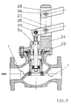
- Figure 3 shows a pilot operated pressure reducing or float valve.
- the actuation force required for the pilot-operated valves has hitherto been achieved with multi-cylinder, stepped bushings and pistons, in which the merging cylinders of different diameters form the differential areas which bring about the differential piston effect.
- the differential piston effect is realized differently in an astonishingly simple manner, while the piston and housing bushing are simple cylindrical bodies.
- Inside the housing bushing there is a two-part piston, consisting of a long piston part 6a and a piston disk 6b, which are connected to one another by the piston rod 5b.
- An intermediate base 30 is located between the two piston parts.
- the intermediate base is fastened in the housing bushing by means of a multi-part ring 32, which partially sits within a groove-like recess 11a in the housing bushing 11.
- the intermediate floor consists of two disks 30a, 30b, the lower disk 30b around the passage for the piston rod, a neck-shaped extension 31 for the Centering the spring has.
- the piston disc 6b is turned towards the piston rod so that the control bore in the housing bushing cannot be run over.
- Intermediate base 30a, 30b and piston disc 6b form differential surfaces that are required to produce the differential piston effect. In this way it is possible to use the simple cylindrically shaped pistons and housing bushing with their constant diameters even with the pilot operated valve.
- the piston disc 6b is short on its running surface along the inner surface of the housing bushing and rounded at the upper and lower end of the running surface in order to avoid jamming or jamming.
- In the piston rod 5 there is an axial bore 33, which connects the space above the long piston part and the space above the piston disc to compensate for pressure.
- a piston ring 20a is arranged in a groove-like recess in the piston disc 6b between the two discs of the intermediate floor. This piston ring 20a has a play in the radial direction, which causes automatic ventilation.
- the described invention can of course be used for all types of piston valves, for example also for overflow valves and safety valves.
Landscapes
- Engineering & Computer Science (AREA)
- General Engineering & Computer Science (AREA)
- Mechanical Engineering (AREA)
- Fluid-Driven Valves (AREA)
- Valve Device For Special Equipments (AREA)
- Compressor (AREA)
- Actuator (AREA)
- Catching Or Destruction (AREA)
- External Artificial Organs (AREA)
- Pens And Brushes (AREA)
Claims (29)
- Robinet comprenant un corps (1), un couvercle (2, 23) et un manchon intérieur (11) conjugés au corps, un piston (6) et une bague formant siège (13), qui est manoeuvré par un dispositif de commande (5, 3, 4; 7, 8, 9), dans lequel le piston (6) et le manchon (11) sont des pièces de forme cylindrique simple ayant un diamètre essentiellement constant et dans lequel le manchon (11) est centré d'un côté dans la bague formant siège (13), caractérisé en ce que le manchon (11) est fixé et centré de l'autre côté dans le corps (1), à distance de celui-ci, par une bague de maintien (16), et que le couvercle (2, 23) est centré sur le corps (1) par la surface intérieure de la partie supérieure du manchon (11).
- Robinet selon la revendication 1, caractérisé en ce que le dessous du couvercle (2, 23) présente un évidement (17) dans lequel pénètre le bord supérieur du manchon (11).
- Robinet selon une des revendications précédentes, caractérisé en ce que la surface intérieure du piston (6) présente une saillie (18) semblable à un collet ou une gorge.
- Robinet selon une des revendications précédentes, caractérisé en ce que le piston (6) et la tige filetée de commande (5) du dispositif de commande (5, 3, 4; 7, 8, 9) sont reliés entre eux au moyen d'une pièce de liaison séparée (19) disposée sur la saillie (18) semblable à un collet.
- Robinet selon la revendication 4, caractérisé en ce que la pièce de liaison (19) est reliée fixe à la tige filetée de commande (5) et présente du jeu autour de la saillie (18) semblable à un collet.
- Robinet selon la revendication 4 ou 5, caractérisé en ce que la pièce de liaison (19) est constituée de deux disques.
- Robinet selon la revendication 6, caractérisé en ce que les disques (19) présentent des orifices d'égalisation de pression (21) qui débouchent dans une gorge (22).
- Robinet selon une des revendications précédentes, caractérisé en ce que le manchon (11) et la bague formant siège (13) définissent un logement dans lequel peut être placé un joint d'étanchéité (13a).
- Robinet selon une des revendications précédentes, caractérisé en ce que le couvercle (2), pouvant avoir une grandeur variable en fonction du diamètre nomibal du robinet, présente une ouverte centrale de même grandeur pour des robinets de diamètres nominaux allant de DN 50 à DN 200.
- Robinet selon la revendication 9, caractérisé en ce que la même tige filetée de commande (tige de piston 5, 5a) est utilisable sur des robinets dont le diamètre nominal est compris entre DN 50 et DN 200.
- Robinet selon la revendication 9, caractérisé en ce que le même dispositif de commande (5, 3, 4; 7, 8, 9) est utilisable sur des robinets dont les diamètres nominaux sont compris entre DN 50 et DN 200.
- Robinet selon une des revendications précédentes, caractérisé en ce qu'il est un robinet de réglage.
- Robinet selon la revendication 12 avec un dispositif de commande comprenant une tige filetée de commande (5), un index (9), un chapeau en colonne (3), une bride de commande (4) et un système de commande (70), caractérisé en ce que différents systèmes de commande (70) peuvent être montés au choix sur la bride de commande (4).
- Robinet selon la revendication 13, caractérisé en ce que le système de commande (70) est un volant actionné manuellement, une roue à chaîne, une douille de commande et ainsi de suite ou une commande électrique à rotation.
- Robinet selon une des revendications 1 à 10, caractérisé en ce qu'il est un robinet à flotteur à commande directe.
- Robinet selon la revendication 14, caractérisé en ce que la tige filetée de commande (tige de piston 5a) est montée à double palier dans le couvercle (23).
- Robinet selon la revendication 15, caractérisé en ce que le support (24) pour la timonerie du flotteur est formé sur le couvercle (23) lors de la coulée de celui-ci.
- Robinet selon la revendication 17, caractérisé en ce que le support (24) présente des raccordements (25, 26) pour un ou plusieurs leviers (27, 28).
- Robinet selon la revendication 18, caractérisé en ce qu'un trou oblong (29) est ménagé dans le levier (27).
- Robinet selon une des revendications 1 à 4 et 6 à 8, caractérisé en ce qu'il est un manodétendeur piloté ou un robinet à flotteur piloté.
- Robinet selon la revendication 20, caractérisé en ce que le piston est constitué d'une longue partie de piston (6a) et d'un disque (6b) qui sont reliés entre eux par une tige de piston (5b).
- Robinet selon la revendication 21, caractérisé en ce qu'un fond intermédiaire (30a, 30b) est disposé entre le manchon (11) et la tige de piston (5b) et entre la longue partie de piston (6a) et le disque (6b) du piston.
- Robinet selon la revendication 22, caractérisé en ce que le fond intermédiaire (30a, 30b) est disposé sur une saillie semblabe à un collet ou dans un évidement (11a) semblable à une gorge de la surface intérieure du manchon (11).
- Robinet selon la revendication 22 ou 23, caractérisé en ce que le fond intermédiaire comporte deux disques (30a, 30b) pourvus d'un passage pour la tige de piston (5b) et dont le disque inférieur présente, autour du passage pour la tige de piston (5b), un prolongement (31) en forme de col pour le centrage d'un ressort.
- Robinet selon une des revendications 22 à 24, caractérisé en ce que le disque (6b) du piston possède une portée s'étendant sur une courte longueur le long du manchon (11) et ayant des extrémités supérieure et inférieure arrondies.
- Robinet selon une des revendications 22 à 25, caractérisé en ce que le disque (6b) du piston possède sur son dessous une configuration façonnée au tour dirigée vers la longue partie de piston (6a).
- Robinet selon une des revendications 22 à 26, caractérisé en ce que la tige de piston (5b) présente un perçage (33) qui fait communiquer entre eux l'espace au-dessus de la longue partie de piston (6a) et l'espace au-dessus du disque (6b) du piston.
- Robinet selon une des revendications 24 à 27, caractérisé en ce qu'un segment de piston (20a), servant à étancher la tige de piston, est disposé avec du jeu en direction radiale dans un évidement des disques (30a, 30b) du fond intermédiaire.
- Robinet selon une des revendications 22 à 28, caractérisé en ce qu'un segment de piston (20) est disposé dans la région de l'extrémité inférieure du piston (6a) entre celui-ci et le manchon (11).
Priority Applications (1)
| Application Number | Priority Date | Filing Date | Title |
|---|---|---|---|
| AT89114692T ATE99397T1 (de) | 1988-10-07 | 1989-08-09 | Kolbenventil mit flexibler antriebseinrichtung. |
Applications Claiming Priority (2)
| Application Number | Priority Date | Filing Date | Title |
|---|---|---|---|
| DE3834173A DE3834173C3 (de) | 1988-10-07 | 1988-10-07 | Kolbenventil mit flexibler Antriebseinrichtung |
| DE3834173 | 1988-10-07 |
Publications (3)
| Publication Number | Publication Date |
|---|---|
| EP0362518A2 EP0362518A2 (fr) | 1990-04-11 |
| EP0362518A3 EP0362518A3 (en) | 1990-08-22 |
| EP0362518B1 true EP0362518B1 (fr) | 1993-12-29 |
Family
ID=6364616
Family Applications (1)
| Application Number | Title | Priority Date | Filing Date |
|---|---|---|---|
| EP89114692A Expired - Lifetime EP0362518B1 (fr) | 1988-10-07 | 1989-08-09 | Tiroir cylindrique avec dispositif de commande flexible |
Country Status (9)
| Country | Link |
|---|---|
| EP (1) | EP0362518B1 (fr) |
| AT (1) | ATE99397T1 (fr) |
| DE (2) | DE3834173C3 (fr) |
| DK (1) | DK495489A (fr) |
| ES (1) | ES2047619T3 (fr) |
| IE (1) | IE62732B1 (fr) |
| NO (1) | NO175952C (fr) |
| PT (1) | PT91911B (fr) |
| TR (1) | TR26281A (fr) |
Cited By (1)
| Publication number | Priority date | Publication date | Assignee | Title |
|---|---|---|---|---|
| DE102023127420A1 (de) * | 2023-09-15 | 2025-03-20 | Volker Wurzer | Ventil |
Families Citing this family (3)
| Publication number | Priority date | Publication date | Assignee | Title |
|---|---|---|---|---|
| US5427358A (en) * | 1994-06-23 | 1995-06-27 | Fisher Controls International, Inc. | Sweep flow valve with removable valve seat |
| RU2200265C1 (ru) * | 2001-06-08 | 2003-03-10 | Малина Петр Васильевич | Клапан |
| DE102017123396A1 (de) * | 2017-10-09 | 2019-04-11 | Samson Aktiengesellschaft | Hubventil und Anordnung für ein Hubventil |
Family Cites Families (7)
| Publication number | Priority date | Publication date | Assignee | Title |
|---|---|---|---|---|
| BE505335A (fr) * | ||||
| NL6807652A (fr) * | 1967-09-11 | 1969-03-13 | ||
| US3648718A (en) * | 1970-06-01 | 1972-03-14 | Foxboro Co | Valve structure |
| DE2507513B2 (de) * | 1975-02-21 | 1978-03-16 | Deutsche Forschungs- Und Versuchsanstalt Fuer Luft- Und Raumfahrt E.V., 5000 Koeln | Ventil zur Steuerung des Druckes und/oder der Menge strömender Medien |
| CH635909A5 (de) * | 1979-02-28 | 1983-04-29 | Elektrowatt Ag | Ventil. |
| EP0227854B1 (fr) * | 1985-12-30 | 1990-05-09 | Johannes Erhard, H. Waldenmaier Erben Süddeutsche Armaturenfabrik GmbH & Co. | Dispositif de réduction de pression |
| DE8807860U1 (de) * | 1988-06-17 | 1988-08-04 | Albrecht-Automatik GmbH & Co, 5024 Pulheim | Handventil |
-
1988
- 1988-10-07 DE DE3834173A patent/DE3834173C3/de not_active Expired - Fee Related
-
1989
- 1989-08-09 AT AT89114692T patent/ATE99397T1/de active
- 1989-08-09 ES ES89114692T patent/ES2047619T3/es not_active Expired - Lifetime
- 1989-08-09 DE DE89114692T patent/DE58906557D1/de not_active Expired - Fee Related
- 1989-08-09 EP EP89114692A patent/EP0362518B1/fr not_active Expired - Lifetime
- 1989-10-02 NO NO893903A patent/NO175952C/no unknown
- 1989-10-04 TR TR89/0817A patent/TR26281A/xx unknown
- 1989-10-04 PT PT91911A patent/PT91911B/pt not_active IP Right Cessation
- 1989-10-06 IE IE322289A patent/IE62732B1/en not_active IP Right Cessation
- 1989-10-06 DK DK495489A patent/DK495489A/da not_active Application Discontinuation
Cited By (1)
| Publication number | Priority date | Publication date | Assignee | Title |
|---|---|---|---|---|
| DE102023127420A1 (de) * | 2023-09-15 | 2025-03-20 | Volker Wurzer | Ventil |
Also Published As
| Publication number | Publication date |
|---|---|
| DE3834173A1 (de) | 1990-04-12 |
| DE58906557D1 (de) | 1994-02-10 |
| DE3834173C2 (fr) | 1992-02-20 |
| EP0362518A3 (en) | 1990-08-22 |
| NO175952B (no) | 1994-09-26 |
| EP0362518A2 (fr) | 1990-04-11 |
| IE893222L (en) | 1990-04-07 |
| DK495489A (da) | 1990-04-08 |
| TR26281A (tr) | 1994-02-09 |
| IE62732B1 (en) | 1995-02-22 |
| NO893903D0 (no) | 1989-10-02 |
| PT91911B (pt) | 1991-05-22 |
| DE3834173C3 (de) | 1994-07-28 |
| NO175952C (no) | 1995-01-04 |
| DK495489D0 (da) | 1989-10-06 |
| ATE99397T1 (de) | 1994-01-15 |
| NO893903L (no) | 1990-04-09 |
| ES2047619T3 (es) | 1994-03-01 |
Similar Documents
| Publication | Publication Date | Title |
|---|---|---|
| DE3540310C2 (fr) | ||
| EP0522285B1 (fr) | Servomoteur pneumatique à membrane | |
| DE1285819B (de) | Mehrfachsteuerventil | |
| DE10203886B4 (de) | Vorsteuerventil | |
| DE2204219A1 (de) | Durchflußregelsystem | |
| AT391176B (de) | Steuerscheibenventil, insbesondere fuer den sanitaerbereich | |
| DE2707134C2 (fr) | ||
| DE3701211A1 (de) | Stroemungsmittelventilaufbau | |
| EP0027854A1 (fr) | Commande électrohydraulique | |
| DE3507278C2 (fr) | ||
| EP0829892A1 (fr) | Moteur hydraulique | |
| DE1947117A1 (de) | Stroemungsregler und Verfahren zur Herstellung desselben | |
| DE3834173C2 (fr) | ||
| EP0059887A1 (fr) | Vanne de réduction de pression | |
| DE1915267B2 (de) | Einstroemkasten fuer duesengruppenregelung von dampfturbinen | |
| DE3108973C2 (fr) | ||
| DE69715111T2 (de) | Durchflussregelventil | |
| AT390313B (de) | Kolbenschieberventil | |
| DE3625058A1 (de) | Ventil | |
| DE8812606U1 (de) | Kolbenventil mit flexibler Antriebseinrichtung | |
| DE2637217A1 (de) | Absperrschieber mit zweiteiliger schieberzunge | |
| DE10014906A1 (de) | Mehrwegeventil (Deckelbefestigung) | |
| DE69401196T2 (de) | Abblasventil für ein dampfgefäss | |
| DE3131943C2 (de) | Absperrschieber mit bei der Betätigung im Normalbetrieb axial feststehender Gewindespindel | |
| DE69407982T2 (de) | Lagerung einer schneckenwelle |
Legal Events
| Date | Code | Title | Description |
|---|---|---|---|
| PUAI | Public reference made under article 153(3) epc to a published international application that has entered the european phase |
Free format text: ORIGINAL CODE: 0009012 |
|
| AK | Designated contracting states |
Kind code of ref document: A2 Designated state(s): AT BE CH DE ES FR GB GR IT LI LU NL SE |
|
| PUAL | Search report despatched |
Free format text: ORIGINAL CODE: 0009013 |
|
| AK | Designated contracting states |
Kind code of ref document: A3 Designated state(s): AT BE CH DE ES FR GB GR IT LI LU NL SE |
|
| 17P | Request for examination filed |
Effective date: 19900907 |
|
| 17Q | First examination report despatched |
Effective date: 19920129 |
|
| GRAA | (expected) grant |
Free format text: ORIGINAL CODE: 0009210 |
|
| AK | Designated contracting states |
Kind code of ref document: B1 Designated state(s): AT BE CH DE ES FR GB GR IT LI LU NL SE |
|
| REF | Corresponds to: |
Ref document number: 99397 Country of ref document: AT Date of ref document: 19940115 Kind code of ref document: T |
|
| REF | Corresponds to: |
Ref document number: 58906557 Country of ref document: DE Date of ref document: 19940210 |
|
| GBT | Gb: translation of ep patent filed (gb section 77(6)(a)/1977) |
Effective date: 19940117 |
|
| REG | Reference to a national code |
Ref country code: ES Ref legal event code: FG2A Ref document number: 2047619 Country of ref document: ES Kind code of ref document: T3 |
|
| ET | Fr: translation filed | ||
| ITF | It: translation for a ep patent filed | ||
| REG | Reference to a national code |
Ref country code: GR Ref legal event code: FG4A Free format text: 3011232 |
|
| EPTA | Lu: last paid annual fee | ||
| PLBE | No opposition filed within time limit |
Free format text: ORIGINAL CODE: 0009261 |
|
| STAA | Information on the status of an ep patent application or granted ep patent |
Free format text: STATUS: NO OPPOSITION FILED WITHIN TIME LIMIT |
|
| 26N | No opposition filed | ||
| EAL | Se: european patent in force in sweden |
Ref document number: 89114692.0 |
|
| PGFP | Annual fee paid to national office [announced via postgrant information from national office to epo] |
Ref country code: BE Payment date: 19950607 Year of fee payment: 7 |
|
| PGFP | Annual fee paid to national office [announced via postgrant information from national office to epo] |
Ref country code: FR Payment date: 19950623 Year of fee payment: 7 |
|
| PGFP | Annual fee paid to national office [announced via postgrant information from national office to epo] |
Ref country code: LU Payment date: 19950701 Year of fee payment: 7 |
|
| PGFP | Annual fee paid to national office [announced via postgrant information from national office to epo] |
Ref country code: SE Payment date: 19950706 Year of fee payment: 7 |
|
| PGFP | Annual fee paid to national office [announced via postgrant information from national office to epo] |
Ref country code: GR Payment date: 19950725 Year of fee payment: 7 |
|
| PGFP | Annual fee paid to national office [announced via postgrant information from national office to epo] |
Ref country code: NL Payment date: 19950831 Year of fee payment: 7 |
|
| PGFP | Annual fee paid to national office [announced via postgrant information from national office to epo] |
Ref country code: ES Payment date: 19960802 Year of fee payment: 8 |
|
| PG25 | Lapsed in a contracting state [announced via postgrant information from national office to epo] |
Ref country code: LU Free format text: LAPSE BECAUSE OF NON-PAYMENT OF DUE FEES Effective date: 19960809 |
|
| PG25 | Lapsed in a contracting state [announced via postgrant information from national office to epo] |
Ref country code: SE Effective date: 19960810 |
|
| PG25 | Lapsed in a contracting state [announced via postgrant information from national office to epo] |
Ref country code: BE Effective date: 19960831 |
|
| BERE | Be: lapsed |
Owner name: JOHANNES ERHARD H. WALDENMAIER ERBEN SUDDEUTSCHE Effective date: 19960831 |
|
| PG25 | Lapsed in a contracting state [announced via postgrant information from national office to epo] |
Ref country code: GR Free format text: THE PATENT HAS BEEN ANNULLED BY A DECISION OF A NATIONAL AUTHORITY Effective date: 19970228 |
|
| PG25 | Lapsed in a contracting state [announced via postgrant information from national office to epo] |
Ref country code: NL Effective date: 19970301 |
|
| REG | Reference to a national code |
Ref country code: GR Ref legal event code: MM2A Free format text: 3011232 |
|
| PG25 | Lapsed in a contracting state [announced via postgrant information from national office to epo] |
Ref country code: FR Effective date: 19970430 |
|
| NLV4 | Nl: lapsed or anulled due to non-payment of the annual fee |
Effective date: 19970301 |
|
| EUG | Se: european patent has lapsed |
Ref document number: 89114692.0 |
|
| REG | Reference to a national code |
Ref country code: FR Ref legal event code: ST |
|
| PG25 | Lapsed in a contracting state [announced via postgrant information from national office to epo] |
Ref country code: ES Free format text: LAPSE BECAUSE OF THE APPLICANT RENOUNCES Effective date: 19970811 |
|
| PGFP | Annual fee paid to national office [announced via postgrant information from national office to epo] |
Ref country code: CH Payment date: 19970815 Year of fee payment: 9 |
|
| PGFP | Annual fee paid to national office [announced via postgrant information from national office to epo] |
Ref country code: GB Payment date: 19980731 Year of fee payment: 10 |
|
| PGFP | Annual fee paid to national office [announced via postgrant information from national office to epo] |
Ref country code: DE Payment date: 19980803 Year of fee payment: 10 |
|
| PGFP | Annual fee paid to national office [announced via postgrant information from national office to epo] |
Ref country code: AT Payment date: 19980828 Year of fee payment: 10 |
|
| PG25 | Lapsed in a contracting state [announced via postgrant information from national office to epo] |
Ref country code: LI Free format text: LAPSE BECAUSE OF NON-PAYMENT OF DUE FEES Effective date: 19980831 Ref country code: CH Free format text: LAPSE BECAUSE OF NON-PAYMENT OF DUE FEES Effective date: 19980831 |
|
| REG | Reference to a national code |
Ref country code: CH Ref legal event code: PL |
|
| PG25 | Lapsed in a contracting state [announced via postgrant information from national office to epo] |
Ref country code: GB Free format text: LAPSE BECAUSE OF NON-PAYMENT OF DUE FEES Effective date: 19990809 Ref country code: AT Free format text: LAPSE BECAUSE OF NON-PAYMENT OF DUE FEES Effective date: 19990809 |
|
| GBPC | Gb: european patent ceased through non-payment of renewal fee |
Effective date: 19990809 |
|
| PG25 | Lapsed in a contracting state [announced via postgrant information from national office to epo] |
Ref country code: DE Free format text: LAPSE BECAUSE OF NON-PAYMENT OF DUE FEES Effective date: 20000601 |
|
| REG | Reference to a national code |
Ref country code: ES Ref legal event code: FD2A Effective date: 20001009 |
|
| PG25 | Lapsed in a contracting state [announced via postgrant information from national office to epo] |
Ref country code: IT Free format text: LAPSE BECAUSE OF NON-PAYMENT OF DUE FEES;WARNING: LAPSES OF ITALIAN PATENTS WITH EFFECTIVE DATE BEFORE 2007 MAY HAVE OCCURRED AT ANY TIME BEFORE 2007. THE CORRECT EFFECTIVE DATE MAY BE DIFFERENT FROM THE ONE RECORDED. Effective date: 20050809 |