EP0362552A1 - Verfahren zum Befüllen mit einer Flüssigkeit und anschliessenden Verschweissen eines Behälters - Google Patents
Verfahren zum Befüllen mit einer Flüssigkeit und anschliessenden Verschweissen eines Behälters Download PDFInfo
- Publication number
- EP0362552A1 EP0362552A1 EP89115977A EP89115977A EP0362552A1 EP 0362552 A1 EP0362552 A1 EP 0362552A1 EP 89115977 A EP89115977 A EP 89115977A EP 89115977 A EP89115977 A EP 89115977A EP 0362552 A1 EP0362552 A1 EP 0362552A1
- Authority
- EP
- European Patent Office
- Prior art keywords
- container
- filling
- negative pressure
- welding process
- welding
- Prior art date
- Legal status (The legal status is an assumption and is not a legal conclusion. Google has not performed a legal analysis and makes no representation as to the accuracy of the status listed.)
- Granted
Links
- 238000000034 method Methods 0.000 title claims abstract description 40
- 239000007788 liquid Substances 0.000 title description 3
- 238000007789 sealing Methods 0.000 title 1
- 238000003466 welding Methods 0.000 claims abstract description 26
- 239000000945 filler Substances 0.000 claims abstract description 13
- 230000005489 elastic deformation Effects 0.000 claims abstract description 3
- 239000006260 foam Substances 0.000 claims description 2
- 239000000463 material Substances 0.000 description 5
- 238000006073 displacement reaction Methods 0.000 description 4
- 238000000465 moulding Methods 0.000 description 4
- 230000015572 biosynthetic process Effects 0.000 description 1
- 238000007664 blowing Methods 0.000 description 1
- 238000005429 filling process Methods 0.000 description 1
- 238000001802 infusion Methods 0.000 description 1
- 238000004519 manufacturing process Methods 0.000 description 1
Images

Classifications
-
- B—PERFORMING OPERATIONS; TRANSPORTING
- B65—CONVEYING; PACKING; STORING; HANDLING THIN OR FILAMENTARY MATERIAL
- B65B—MACHINES, APPARATUS OR DEVICES FOR, OR METHODS OF, PACKAGING ARTICLES OR MATERIALS; UNPACKING
- B65B3/00—Packaging plastic material, semiliquids, liquids or mixed solids and liquids, in individual containers or receptacles, e.g. bags, sacks, boxes, cartons, cans, or jars
- B65B3/02—Machines characterised by the incorporation of means for making the containers or receptacles
- B65B3/022—Making containers by moulding of a thermoplastic material
-
- B—PERFORMING OPERATIONS; TRANSPORTING
- B65—CONVEYING; PACKING; STORING; HANDLING THIN OR FILAMENTARY MATERIAL
- B65B—MACHINES, APPARATUS OR DEVICES FOR, OR METHODS OF, PACKAGING ARTICLES OR MATERIALS; UNPACKING
- B65B3/00—Packaging plastic material, semiliquids, liquids or mixed solids and liquids, in individual containers or receptacles, e.g. bags, sacks, boxes, cartons, cans, or jars
- B65B3/18—Controlling escape of air from containers or receptacles during filling
-
- B—PERFORMING OPERATIONS; TRANSPORTING
- B67—OPENING, CLOSING OR CLEANING BOTTLES, JARS OR SIMILAR CONTAINERS; LIQUID HANDLING
- B67C—CLEANING, FILLING WITH LIQUIDS OR SEMILIQUIDS, OR EMPTYING, OF BOTTLES, JARS, CANS, CASKS, BARRELS, OR SIMILAR CONTAINERS, NOT OTHERWISE PROVIDED FOR; FUNNELS
- B67C3/00—Bottling liquids or semiliquids; Filling jars or cans with liquids or semiliquids using bottling or like apparatus; Filling casks or barrels with liquids or semiliquids
- B67C3/02—Bottling liquids or semiliquids; Filling jars or cans with liquids or semiliquids using bottling or like apparatus
- B67C3/22—Details
- B67C3/222—Head-space air removing devices, e.g. by inducing foam
- B67C3/223—Head-space air removing devices, e.g. by inducing foam by squeezing the container elastically
-
- B—PERFORMING OPERATIONS; TRANSPORTING
- B29—WORKING OF PLASTICS; WORKING OF SUBSTANCES IN A PLASTIC STATE IN GENERAL
- B29C—SHAPING OR JOINING OF PLASTICS; SHAPING OF MATERIAL IN A PLASTIC STATE, NOT OTHERWISE PROVIDED FOR; AFTER-TREATMENT OF THE SHAPED PRODUCTS, e.g. REPAIRING
- B29C49/00—Blow-moulding, i.e. blowing a preform or parison to a desired shape within a mould; Apparatus therefor
- B29C49/42—Component parts, details or accessories; Auxiliary operations
- B29C49/46—Component parts, details or accessories; Auxiliary operations characterised by using particular environment or blow fluids other than air
- B29C2049/4602—Blowing fluids
- B29C2049/465—Blowing fluids being incompressible
- B29C2049/4664—Blowing fluids being incompressible staying in the final article
-
- B—PERFORMING OPERATIONS; TRANSPORTING
- B29—WORKING OF PLASTICS; WORKING OF SUBSTANCES IN A PLASTIC STATE IN GENERAL
- B29C—SHAPING OR JOINING OF PLASTICS; SHAPING OF MATERIAL IN A PLASTIC STATE, NOT OTHERWISE PROVIDED FOR; AFTER-TREATMENT OF THE SHAPED PRODUCTS, e.g. REPAIRING
- B29C49/00—Blow-moulding, i.e. blowing a preform or parison to a desired shape within a mould; Apparatus therefor
- B29C49/42—Component parts, details or accessories; Auxiliary operations
- B29C49/4273—Auxiliary operations after the blow-moulding operation not otherwise provided for
- B29C49/428—Joining
- B29C49/42802—Joining a closure or a sealing foil to the article or pincing the opening
-
- B—PERFORMING OPERATIONS; TRANSPORTING
- B29—WORKING OF PLASTICS; WORKING OF SUBSTANCES IN A PLASTIC STATE IN GENERAL
- B29C—SHAPING OR JOINING OF PLASTICS; SHAPING OF MATERIAL IN A PLASTIC STATE, NOT OTHERWISE PROVIDED FOR; AFTER-TREATMENT OF THE SHAPED PRODUCTS, e.g. REPAIRING
- B29C49/00—Blow-moulding, i.e. blowing a preform or parison to a desired shape within a mould; Apparatus therefor
- B29C49/42—Component parts, details or accessories; Auxiliary operations
- B29C49/4273—Auxiliary operations after the blow-moulding operation not otherwise provided for
- B29C49/42815—Emptying the article, e.g. emptying hydraulic blowing fluid
-
- B—PERFORMING OPERATIONS; TRANSPORTING
- B29—WORKING OF PLASTICS; WORKING OF SUBSTANCES IN A PLASTIC STATE IN GENERAL
- B29C—SHAPING OR JOINING OF PLASTICS; SHAPING OF MATERIAL IN A PLASTIC STATE, NOT OTHERWISE PROVIDED FOR; AFTER-TREATMENT OF THE SHAPED PRODUCTS, e.g. REPAIRING
- B29C49/00—Blow-moulding, i.e. blowing a preform or parison to a desired shape within a mould; Apparatus therefor
- B29C49/42—Component parts, details or accessories; Auxiliary operations
- B29C49/4273—Auxiliary operations after the blow-moulding operation not otherwise provided for
- B29C49/4283—Deforming the finished article
-
- B—PERFORMING OPERATIONS; TRANSPORTING
- B29—WORKING OF PLASTICS; WORKING OF SUBSTANCES IN A PLASTIC STATE IN GENERAL
- B29C—SHAPING OR JOINING OF PLASTICS; SHAPING OF MATERIAL IN A PLASTIC STATE, NOT OTHERWISE PROVIDED FOR; AFTER-TREATMENT OF THE SHAPED PRODUCTS, e.g. REPAIRING
- B29C49/00—Blow-moulding, i.e. blowing a preform or parison to a desired shape within a mould; Apparatus therefor
- B29C49/42—Component parts, details or accessories; Auxiliary operations
- B29C49/4289—Valve constructions or configurations, e.g. arranged to reduce blowing fluid consumption
-
- B—PERFORMING OPERATIONS; TRANSPORTING
- B29—WORKING OF PLASTICS; WORKING OF SUBSTANCES IN A PLASTIC STATE IN GENERAL
- B29C—SHAPING OR JOINING OF PLASTICS; SHAPING OF MATERIAL IN A PLASTIC STATE, NOT OTHERWISE PROVIDED FOR; AFTER-TREATMENT OF THE SHAPED PRODUCTS, e.g. REPAIRING
- B29C49/00—Blow-moulding, i.e. blowing a preform or parison to a desired shape within a mould; Apparatus therefor
- B29C49/42—Component parts, details or accessories; Auxiliary operations
- B29C49/48—Moulds
- B29C49/4802—Moulds with means for locally compressing part(s) of the parison in the main blowing cavity
- B29C49/4817—Moulds with means for locally compressing part(s) of the parison in the main blowing cavity with means for closing off parison ends
-
- B—PERFORMING OPERATIONS; TRANSPORTING
- B29—WORKING OF PLASTICS; WORKING OF SUBSTANCES IN A PLASTIC STATE IN GENERAL
- B29C—SHAPING OR JOINING OF PLASTICS; SHAPING OF MATERIAL IN A PLASTIC STATE, NOT OTHERWISE PROVIDED FOR; AFTER-TREATMENT OF THE SHAPED PRODUCTS, e.g. REPAIRING
- B29C49/00—Blow-moulding, i.e. blowing a preform or parison to a desired shape within a mould; Apparatus therefor
- B29C49/42—Component parts, details or accessories; Auxiliary operations
- B29C49/58—Blowing means
-
- B—PERFORMING OPERATIONS; TRANSPORTING
- B29—WORKING OF PLASTICS; WORKING OF SUBSTANCES IN A PLASTIC STATE IN GENERAL
- B29L—INDEXING SCHEME ASSOCIATED WITH SUBCLASS B29C, RELATING TO PARTICULAR ARTICLES
- B29L2031/00—Other particular articles
- B29L2031/712—Containers; Packaging elements or accessories, Packages
- B29L2031/7158—Bottles
Definitions
- the invention relates to a method for filling and subsequent pore-tight welding of a container which is elastically deformable at least in some areas and which has a filler neck, the cross-section of which is smaller than that of the container and which, after filling, is flattened and welded at least in its edge area, after filling the filling level in the container is raised by an elastic deformation of the container and the size of the passage opening of the filler neck is reduced in a first welding process and then the mouth opening of the filler neck remaining after the first welding process is welded in a second welding process.
- a device provided for carrying out such a process belonging to the prior art is known from DE utility model 87 08 939.4.
- This method can be achieved in that in the finished container, i.e. the filled and sealed by the final welding process, only an insignificant amount of residual air is contained, the volume of which practically corresponds to that of the filler neck thanks to the process step of lifting the fill level in the first welding process, the reduction in the opening of the filler neck is a relatively small volume. Because of the small amount of air enclosed, containers filled with this method are therefore well suited, for example, for infusion purposes.
- the invention has for its object to remedy this situation by showing a method by which a completely pore-tight closure of the container is always ensured.
- this object is achieved according to the invention in that during at least a portion of the period between the beginning of the lifting of the filling level and the beginning of the second welding process, a negative pressure is applied to the filler neck of the container and formed by the filled product above vapors, mists or foams from the filling level are at least partially extracted.
- This additional process step protects the weld, irrespective of the properties of the filling material, against moistening by access of the filling material, so that a pore-tight closure of the container is ensured.
- the method according to the invention can be carried out in a simple manner. For example, one can proceed in such a way that when using a filling mandrel, as is usually used for supplying the filling material to the container and for removing the exhaust air during the filling process, the exhaust air line of the filling mandrel is connected to a suction air line for a desired period of time.
- a filling mandrel as is usually used for supplying the filling material to the container and for removing the exhaust air during the filling process
- the exhaust air line of the filling mandrel is connected to a suction air line for a desired period of time.
- the first welding process is preferably carried out after the application of the negative pressure has ended.
- the filling mandrel via the exhaust air line of which the negative pressure has been applied, lifts off the container shortly before the highest filling level is reached.
- the first closes Half of the head cheek intended for welding. Shortly afterwards, when the fill level has reached its highest level due to plastic shrinkage, the second half of the head cheek closes.
- a filling mandrel 1 which can be moved in the vertical direction, ie in its longitudinal direction, of which only the front end section is shown in the figures, has an inner, central line 3 for the supply of liquid filling material 5 to a container 7.
- the inner line 3 of the filling mandrel 1 is surrounded by an air line 9 which is formed in the filling mandrel 1 in the form of an annular channel concentric with the line 3.
- the air line 9 is in its expanded upper end section 11 a flexible connecting line 12 is connected to a valve arrangement designated as a whole by 13, see FIGS. 1 and 2.
- the bag 7 is produced in a blowing process from a plastic tube which is introduced into a mold 15 which has shaped bodies 16 and 17 which are movable in the manner customary in such devices, and which has cheek pieces 19 and 20 which are displaceably mounted in the region of the upper end thereof, the latter each have a lower jaw part 21 and an upper jaw part 22.
- the upper jaw parts 22 are separately slidably mounted on the lower pelvic parts 21.
- the molded body 16 is provided with a recess 25 into which a displacement punch 27 is inserted, which can be displaced in the recess 25 between an inactive position shown in FIG. 1 and an effective position shown in FIGS. 2 to 4.
- the working surface of the punch 27 facing the interior of the molding tool 15 is flush with the inner surface of the molded body 16 when the displacement punch 27 is in its inactive position. It then forms part of the mold contact surface for the container 7.
- the valve arrangement 13 has a blown air valve 29 which is opened in order to supply blown air via the line 12 and the air line 9 of the placed mandrel 1 in order to blow mold the container 7 in the molding tool.
- an exhaust air valve 30 belonging to the valve arrangement 13 is opened and the liquid one
- the filling material is fed via the line 3 of the filling mandrel 1 until the filling level 33 in the container 7 has reached the height shown in FIG. 1.
- the exhaust air valve 30 is closed and a suction air valve 31 belonging to the valve arrangement 13 is opened.
- the latter is connected to a negative pressure source, so that a negative pressure is generated via the line 12 and the inner air line 9 of the filling mandrel 1 in the interior of the container 7 located above the filling level 33.
- the filling level 33 is raised by volume displacement, see FIG. 2.
- the mandrel 1 is lifted and the suction air valve 31 is closed.
- the head jaws 19, 20 close with their lower jaw parts 21, whereby the size of the passage opening at the filler neck 35 of the container 7 is reduced in a first welding process, the fill level 33 reaching its maximum height by plastic shrinkage, see FIG. 3 upper jaw parts 22 of the head jaws, as a result of which, in a second welding process, the orifice 36 of the filler neck 35 remaining after the first welding process is welded, see FIG. 4.
- the method could also be carried out in such a way that the mandrel 1 remains placed on the mouth opening 36 while the first welding process is carried out by closing the lower jaw parts 21.
- the negative pressure in the interior of the filler neck 35 could also be carried out while the first welding process is being carried out and until the start of the second Welding process can be maintained.
Landscapes
- Engineering & Computer Science (AREA)
- Mechanical Engineering (AREA)
- Basic Packing Technique (AREA)
- Filling Of Jars Or Cans And Processes For Cleaning And Sealing Jars (AREA)
- Package Closures (AREA)
- Sealing Battery Cases Or Jackets (AREA)
- Closing Of Containers (AREA)
Abstract
Description
- Die Erfindung betrifft ein Verfahren zum Befüllen und anschließenden porendichten Verschweißen eines wenigstens in Teilbereichen elastisch verformbaren Behälters, der einen Einfüllstutzen aufweist, dessen Querschnitt kleiner ist als derjenige des Behälters und der nach dem Befüllen zumindest in seinem Randbereich flachgedrückt und verschweißt wird, wobei nach dem Befüllen der Füllspiegel im Behälter durch eine elastische Deformation des Behälters angehoben wird und wobei in einem ersten Schweißvorgang die Größe der Durchlaßöffnung des Einfüllstutzens verkleinert und danach in einem zweiten Schweißvorgang die nach dem ersten Schweißvorgang verbleibende Mündungsöffnung des Einfüllstutzens verschweißt wird.
- Ein zur Durchführung eines deratigen, zum Stande der Technik gehörenden Verfahrens vorgesehene Vorrichtung ist aus der DE-Gebrauchsmusterschrift 87 08 939.4 bekannt. Durch die Anwendung dieses Verfahrens läßt sich erreichen, daß im fertiggestellten Behälter, also dem befüllten und durch den abschließenden Schweißvorgang dicht verschlossenen Behälter, nur eine unbedeutende Restluftmenge enthalten ist, deren Volumen dank des Verfahrensschritts des Anhebens des Füllspiegels praktisch demjenigen des Einfüllstutzens entspricht, wobei es sich wegen der bei dem ersten Schweißvorgang durchgeführten Verkleinerung der Durchlaßöffunung des Einfüllstutzens um ein verhältnismäßig kleines Volumen handelt. Aufgrund der geringen eingeschlossenen Luftmenge sind nach diesem Verfahren befüllte Behälter daher beispielsweise für Infusionszwecke gut geeignet.
- Wie sich gezeigt hat, ergeben sich bei der Durchführung des üblichen Verfahrens in manchen Fällen jedoch Probleme dahingehend, daß der abschließende Schweißvorgang nicht zu einem völlig porendichten Verschluß führt.
- Der Erfindung liegt die Aufgabe zugrunde, diebezüglich Abhilfe zu schaffen, indem ein Verfahren aufgezeigt wird, durch das stets ein völlig porendichter Verschluß des Behälters sichergestellt wird.
- Bei einem Verfahren der eingangs genannten Art ist diese Aufgabe erfindungsgemäß dadurch gelöst, daß während zumindest einem Teilabschnitt des Zeitraumes zwischen dem Beginn des Anhebens des Füllspiegels und des Beginns des zweiten Schweißvorganges an dem Einfüllstutzen des Behälters ein Unterdruck angelegt und von dem eingefüllten Füllgut gebildete, oberhalb des Füllspiegels befindliche Dämpfe, Nebel oder Schäume zumindest teilweise abgesaugt werden.
- Durch diesen zusätzlichen Verfahrensschritt wird die Schweißstelle, unabhängig von den Eigenschaften des Füllgutes, vor einer Befeuchtung durch Zutritt von Füllgut geschützt, so daß ein porendichter Verschluß des Behälters gewährleistet ist.
- Das erfindungsgemäße Verfahren ist auf einfache Weise durchführbar. Beispielsweise kann so vorgegangen werden, daß bei Verwendung eines Fülldornes, wie er üblicherwiese zum Zuführen des Füllgutes zum Behälter und zum Abführen der Abluft beim Füllvorgang benutzt wird, die Abluftleitung des Fülldornes während eines gewünschten Zeitraums mit einer Saugluftleitung verbunden wird.
- In vielen Fällen werden besonders gute Ergebnisse Erzielt, wenn der Unterdruck von Beginn der Deformation des Behälters, also vom Beginn des Anhebens des Füllspiegels an, bis kurz vor Erreichen des höchsten Füllspiegels durchgehend angelegt wird.
- Im letzteren Fall wird der erste Schweißvorgang vorzugsweise nach Beendigung des Anlegens des Unterdrucks durchgeführt. In einem solchen Fall hebt der Fülldorn, über dessen Abluftleitung der Unterdruck angelegt worden ist, kurz vor Erreichen des höchsten Füllspiegels von dem Behälter ab. Bei Verwendung einer Vorrichtung der erwähnten, aus der DE-Gebrauchsmusterschrift 87 08 939.4 bekannten Art schließt danach die erste Hälfte der zum Verschweißen vorgesehenen Kopfbacke. Kurz danach, wenn der Füllspiegel durch Kunststoffschrumpfung seine größte Pegelhöhe erreicht hat, schließt die zweite Hälfte der Kopfbacke.
- Die Erfindung ist nachstehend anhand eines in der Zeichnung verdeutlichten Ausführungsbeispiels des Verfahrens im einzelnen erläutert.
- Es zeigen:
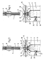
- Fig. 1 und 2 abgebrochen und teils schematisch vereinfacht gezeichnete Vertikalschnitte desjenigen Bereichs einer Vorrichtung zum Durchführen des Verfahrens, in dem ein Fülldorn mit einem Behälter-Formwerkzeug zusammenwirkt, wobei die Vorrichtung in einem ersten, bzw. einem zweiten Betriebszustand gezeigt ist, und
- Fig. 3 und 4 den Fig. 1 und 2 ähnliche Vertikalschnitte, wobei die Vorrichtung in einem dritten bzw. einem vierten Betriebszustand gezeigt ist.
- Ein in Vertikalrichtung, d.h. in seiner Längsrichtung, bewegbarer Fülldorn 1, von dem in den Fig. nur der vordere Endabschnitt gezeigt ist, weist eine innere, zentral gelegene Leitung 3 für die Zufuhr flüssigen Füllgutes 5 zu einem Behälter 7 auf. Die innere Leitung 3 des Fülldornes 1 ist von einer Luftleitung 9 umgeben, die im Fülldorn 1 in Form eines zur Leitung 3 konzentrischen Ringkanals ausgebildet ist. Die Luftleitung 9 ist in ihrem erweiterten oberen Endabschnitt 11 über eine flexible Verbindungsleitung 12 mit einer als Ganzes mit 13 bezeichneten Ventilanordnung verbunden, siehe Fig. 1 und 2.
- Die Herstellung des Beutels 7 erfolgt im Blasverfahren aus einem Kunststoffschlauch, der in ein Formwerkzeug 15 eingebracht wird, das in der bei derartigen Vorrichtungen üblichen Weise bewegliche Formkörper 16 und 17 sowie im Bereich des oberen Endes derselben verschiebbar gelagerte Kopfbacken 19 und 20 aufweist, welch letztere je einen unteren Backenteil 21 und einen oberen Backenteil 22 aufweisen. Die oberen Backenteile 22 sind für sich gesondert verschiebbar an den unteren Beckenteilen 21 gelagert.
- Der Formkörper 16 ist mit einer Aussparung 25 versehen, in die ein Verdrängungsstempel 27 eingesetzt ist, der in der Aussparung 25 zwischen einer in Fig. 1 gezeigten unwirksamen Stellung und einer in Fig. 2 bis 4 gezeigten wirksamen Stellung verschiebbar ist. Die dem Forminnenraum des Formwerkzeugs 15 zugekehrte Arbeitsfläche des Stempels 27 schließt bündig mit der Innenfläche des Formkörpers 16 ab, wenn der Verdrängungsstempel 27 sich in seiner unwirksamen Stellung befindet. Er bildet dann einen Teil der Formanlagefläche für den Behälter 7.
- Für die Herstellung eines gefüllten und verschlossenen Behälters 7 werden nach Einbringen des Kunststoffschlauches in des Formwerkzeug 15 die Formkörper 16, 17 in die Schließstellung gebracht. Die Ventilanordnung 13 weist ein Blasluftventil 29 auf, das geöffnet wird, um Blasluft über die Leitung 12 sowie die Luftleitung 9 des aufgesetzten Fülldorns 1 zuzuführen, um den Behälter 7 im Blasverfahren im Formwerkzeug zu formen. Nach Schließen des Blasluftventils 29 wird ein zur Ventilanordnung 13 gehörendes Abluftventil 30 geöffnet und das flüssige Füllgut über die Leitung 3 des Fülldornes 1 zugeführt, bis der Füllspiegel 33 im Behälter 7 die in Fig. 1 eingezeichnete Höhe erreicht hat. Das Abluftventil 30 wird geschlossen, und ein zur Ventilanordnung 13 gehörendes Saugluftventil 31 wird geöffnet. Letzteres ist mit einer Unterdruckquelle verbunden, so daß über die Leitung 12 sowie die innere Luftleitung 9 des Fülldornes 1 in dem oberhalb des Füllspiegels 33 gelegenen Innenraum des Behälters 7 ein Unterdruck erzeugt wird.
- Durch Verschieben des Verdrängungsstempels 27 aus der in Fig. 1 gezeigten unwirksamen Stellung in die in Fig. 2 bis 4 gezeigte wirksame Stellung wird durch Volumenverdrängung der Füllspiegel 33 angehoben, siehe Fig. 2. Kurz bevor der Füllspiegel 33 die größte Höhe erreicht hat, wird der Fülldorn 1 abgehoben und das Saugluftventil 31 geschlossen. Danach schließen die Kopfbacken 19, 20 mit ihren unteren Backenteilen 21, wodurch in einem ersten Schweißvorgang die Größe der Durchlaßöffnung am Einfüllstutzen 35 des Behälters 7 verkleinert wird, wobei der Füllspiegel 33 durch Kunststoffschrumpfung seine Maximalhöhe erreicht, siehe Fig. 3. Kurz danach schließen die oberen Backenteile 22 der Kopfbacken, wodurch in einem zweiten Schweißvorgang die nach dem ersten Schweißvorgang verbleibende Mündungsöffnung 36 des Einfüllstutzens 35 verschweißt wird, siehe Fig. 4.
- Bei entsprechender Bewegungssteuerung und Ausbildung des Fülldorns 1 könnte das Verfahren auch so durchgeführt werden, daß der Dorn 1 auf die Mündungsöffnung 36 aufgesetzt bleibt, während der erste Schweißvorgang durch Schließen der unteren Backenteile 21 durchgeführt wird. In einem solchen Falle könnte der Unterdruck im Innenraum des Einfüllstutzens 35 auch noch während der Durchführung des ersten Schweißvorgangs und bis zum Beginn des zweiten Schweißvorgangs aufrechterhalten werden.
- Die vorstehende Beschreibung und die Zeichnung beschränken sich nur auf die Angabe von Merkmalen, die für die beispielsweise Verkörperung der Erfindung wesentlich sind. Soweit die Merkmale in der Beschreibung und in der Zeichnung offenbart und in den Ansprüchen nicht genannt sind, dienen sie erforderlichenfalls auch zur Bestimmung des Gegenstandes der Erfindung.
Claims (5)
Applications Claiming Priority (2)
| Application Number | Priority Date | Filing Date | Title |
|---|---|---|---|
| DE3834184 | 1988-10-07 | ||
| DE3834184A DE3834184C1 (de) | 1988-10-07 | 1988-10-07 |
Publications (2)
| Publication Number | Publication Date |
|---|---|
| EP0362552A1 true EP0362552A1 (de) | 1990-04-11 |
| EP0362552B1 EP0362552B1 (de) | 1993-02-03 |
Family
ID=6364623
Family Applications (1)
| Application Number | Title | Priority Date | Filing Date |
|---|---|---|---|
| EP89115977A Expired - Lifetime EP0362552B1 (de) | 1988-10-07 | 1989-08-30 | Verfahren zum Befüllen mit einer Flüssigkeit und anschliessenden Verschweissen eines Behälters |
Country Status (9)
| Country | Link |
|---|---|
| US (1) | US4926613A (de) |
| EP (1) | EP0362552B1 (de) |
| JP (1) | JP2644346B2 (de) |
| CA (1) | CA1306724C (de) |
| DE (1) | DE3834184C1 (de) |
| ES (1) | ES2038386T3 (de) |
| IE (1) | IE62713B1 (de) |
| IN (1) | IN171829B (de) |
| MX (1) | MX172011B (de) |
Cited By (1)
| Publication number | Priority date | Publication date | Assignee | Title |
|---|---|---|---|---|
| WO2020227529A1 (en) * | 2019-05-08 | 2020-11-12 | Prc-Desoto International, Inc. | Sealant cartridge air release apparatus and methods |
Families Citing this family (57)
| Publication number | Priority date | Publication date | Assignee | Title |
|---|---|---|---|---|
| DE3912163A1 (de) * | 1988-10-21 | 1990-04-26 | Thomas Peter | Vorrichtung zur portionierung und abgabe von fluessigkeiten |
| US5060453A (en) * | 1990-07-23 | 1991-10-29 | Sewell Plastics, Inc. | Hot fill container with reconfigurable convex volume control panel |
| US5409124A (en) * | 1993-12-23 | 1995-04-25 | Kraft Foods, Inc. | Beverage container with bottom cavity |
| JP3644992B2 (ja) * | 1994-12-05 | 2005-05-11 | 日本テトラパック株式会社 | 包装容器の充填方法 |
| RU2139229C1 (ru) * | 1994-12-06 | 1999-10-10 | Сосьете Де Продюи Нестле С.А. | Способ удаления кислорода из верхнего пространства упаковки и устройство для его осуществления |
| EP0892736B1 (de) * | 1996-04-02 | 2000-08-30 | Weston Medical Limited | Verfahren zum füllen einer medizinkapsel und dabei erzeugter gegenstand |
| US5809741A (en) * | 1997-04-22 | 1998-09-22 | Tetra Laval Holdings & Finance, Sa | Carton concaving device |
| JP3575306B2 (ja) * | 1998-08-11 | 2004-10-13 | サンスター技研株式会社 | 軟質容器に対する高粘調液の充填方法及び高粘調液の充填装置並びに高粘調液充填容器 |
| JP3575289B2 (ja) * | 1998-08-11 | 2004-10-13 | サンスター技研株式会社 | 筒状部材の搬送システム及び高粘調液の充填システム |
| DE19920761C1 (de) * | 1999-05-05 | 2000-06-29 | Hermann Kronseder | Verfahren und Vorrichtung zum Abfüllen einer Flüssigkeit in Kunststoffflaschen |
| US6666001B2 (en) * | 1999-08-05 | 2003-12-23 | Pepsico Inc. | Plastic container having an outwardly bulged portion |
| US6279789B1 (en) | 1999-12-21 | 2001-08-28 | Owens-Brockway Plastic Products Inc. | Container and closure package and method of filling |
| US6508375B1 (en) | 1999-12-21 | 2003-01-21 | Owens-Brockway Plastic Products Inc. | Container and closure package and a method of filling |
| US6392129B1 (en) * | 2000-10-05 | 2002-05-21 | Latin Percussion, Inc. | Musical instrument and method of making same |
| DE10111084B4 (de) * | 2001-03-08 | 2004-09-30 | Alcoa Deutschland Gmbh Verpackungswerke | Verfahren und Vorrichtung zum Verschließen von Behältern |
| DE10129452A1 (de) * | 2001-06-19 | 2003-01-09 | Bosch Gmbh Robert | Verfahren zum Befüllen von im wesentlichen zylinderförmigen Ampullen |
| JP3969712B2 (ja) * | 2002-06-14 | 2007-09-05 | 東洋自動機株式会社 | 袋詰め包装機における脱気方法及び脱気装置 |
| DE10245318A1 (de) * | 2002-09-27 | 2004-04-08 | Hansen, Bernd, Dipl.-Ing. | Formverfahren, insbesondere Blas- und/oder Vakuumformverfahren, zum Herstellen eines mit einem abzugebenden Medium gefüllten Abgabebehälters |
| SE525036C2 (sv) * | 2003-04-04 | 2004-11-16 | Born To Run Design Hb | Anordning och metod för sterilisering, fyllning och försegling av en förpackning |
| DE10361251A1 (de) * | 2003-12-19 | 2005-07-28 | Arzneimittel Gmbh Apotheker Vetter & Co. Ravensburg | Verfahren zum blasenfreien Befüllen von Karpulen |
| WO2006121815A2 (en) * | 2005-05-06 | 2006-11-16 | Uniloy Milacron Inc. | Method and apparatus for blow molding aseptic closed containers |
| JP4985938B2 (ja) * | 2006-12-28 | 2012-07-25 | 東洋製罐株式会社 | プラスチックボトルに内容液が充填された製品の製造方法及びその製造装置 |
| JP4917911B2 (ja) * | 2007-02-22 | 2012-04-18 | 北海製罐株式会社 | 内容物充填ボトルの製造方法 |
| DE102007015078A1 (de) * | 2007-03-29 | 2008-10-02 | Bernd Hansen | Vorrichtung zum Minimieren des Sauerstoffgehaltes |
| EP2077132A1 (de) | 2008-01-02 | 2009-07-08 | Boehringer Ingelheim Pharma GmbH & Co. KG | Abgabevorrichtung, Aufbewahrungsvorrichtung und Verfahren zur Abgabe einer Formulierung |
| MX2010009838A (es) * | 2008-03-17 | 2010-09-28 | Boehringer Ingelheim Int | Deposito y pulverizador. |
| DE102008028754A1 (de) * | 2008-06-17 | 2009-12-24 | Bernd Hansen | Vorrichtung zum Herstellen und Befüllen von Behältern |
| FR2941923B1 (fr) * | 2009-02-12 | 2012-03-16 | Coopex Apifruit | Procede de conditionnement de denrees perissables tels des fruits, dispositif permettant de le mettre en oeuvre et emballages ainsi obtenus |
| EP2414560B1 (de) | 2009-03-31 | 2013-10-23 | Boehringer Ingelheim International GmbH | Verfahren zur beschichtung einer oberfläche eines bauteils |
| JP5763053B2 (ja) | 2009-05-18 | 2015-08-12 | ベーリンガー インゲルハイム インターナショナル ゲゼルシャフト ミット ベシュレンクテル ハフツング | アダプタ、吸入器具及びアトマイザ |
| BR112012012475B1 (pt) | 2009-11-25 | 2020-03-03 | Boehringer Ingelheim International Gmbh | Nebulizador |
| US10016568B2 (en) | 2009-11-25 | 2018-07-10 | Boehringer Ingelheim International Gmbh | Nebulizer |
| WO2011064163A1 (en) | 2009-11-25 | 2011-06-03 | Boehringer Ingelheim International Gmbh | Nebulizer |
| WO2011160932A1 (en) | 2010-06-24 | 2011-12-29 | Boehringer Ingelheim International Gmbh | Nebulizer |
| DE102010027617A1 (de) * | 2010-07-20 | 2012-01-26 | Bernd Hansen | Verfahren und Vorrichtung zum Herstellen und Befüllen von Behältern aus thermoplastischem Kunststoff sowie derart hergestellter Behälter |
| FR2964950B1 (fr) | 2010-09-20 | 2012-08-31 | Bonduelle Sa Ets | Procede de conditionnement d'un produit liquide. |
| FR2967973B1 (fr) * | 2010-11-25 | 2014-03-14 | Air Liquide | Procede visant a realiser une atmosphere controlee au niveau du ciel gazeux d’un recipient de stockage d’un produit, le recipient etant elabore en un materiau deformable |
| EP2694220B1 (de) | 2011-04-01 | 2020-05-06 | Boehringer Ingelheim International GmbH | Medizinisches gerät mit behälter |
| US9827384B2 (en) | 2011-05-23 | 2017-11-28 | Boehringer Ingelheim International Gmbh | Nebulizer |
| US9440754B2 (en) | 2012-03-29 | 2016-09-13 | R.P. Scherer Technologies, Llc | Three circuit fill system for blow fill seal containers |
| WO2013152894A1 (de) | 2012-04-13 | 2013-10-17 | Boehringer Ingelheim International Gmbh | Zerstäuber mit kodiermitteln |
| JP6280135B2 (ja) * | 2012-12-19 | 2018-02-14 | ディスクマ アクチェンゲゼルシャフト | 容器、並びに容器を製造及び充填する装置及び方法 |
| JP6643231B2 (ja) | 2013-08-09 | 2020-02-12 | ベーリンガー インゲルハイム インターナショナル ゲゼルシャフト ミット ベシュレンクテル ハフツング | ネブライザ |
| ES2836977T3 (es) | 2013-08-09 | 2021-06-28 | Boehringer Ingelheim Int | Nebulizador |
| KR20160067161A (ko) * | 2013-11-06 | 2016-06-13 | 더 프록터 앤드 갬블 캄파니 | 가요성 용기 및 이를 제조하는 방법 |
| RU2016112351A (ru) * | 2013-11-06 | 2017-12-11 | Дзе Проктер Энд Гэмбл Компани | Эластичные контейнеры и способы их изготовления |
| CN116036425A (zh) | 2014-05-07 | 2023-05-02 | 勃林格殷格翰国际有限公司 | 喷雾器、指示器装置及容器 |
| IL247927B (en) | 2014-05-07 | 2022-09-01 | Boehringer Ingelheim Int | Container, a device that turns a liquid into a fine spray and use |
| WO2015169430A1 (en) | 2014-05-07 | 2015-11-12 | Boehringer Ingelheim International Gmbh | Nebulizer |
| US10029407B2 (en) | 2014-12-04 | 2018-07-24 | Big Heart Pet, Inc. | Apparatus, processes, and systems for heat sealing |
| TW201733558A (zh) | 2016-01-06 | 2017-10-01 | 賽諾菲阿凡提斯德意志有限公司 | 藥劑容器及其製造方法 |
| US10179667B2 (en) * | 2016-02-29 | 2019-01-15 | Klocke Verpackungs-Service Gmbh | Method for the production and filling of an application package for a liquid pharmaceutical product |
| CN105858574B (zh) * | 2016-05-31 | 2018-02-02 | 马鞍山市志诚科技有限公司 | 一种灌装液位双轮控制系统 |
| JP6661477B2 (ja) * | 2016-05-31 | 2020-03-11 | 株式会社吉野工業所 | 容器製造方法 |
| IT201800005181A1 (it) * | 2018-05-09 | 2019-11-09 | Procedimento ed apparecchiatura per la realizzazione di una confezione di contenimento di un prodotto. | |
| CN111675173A (zh) * | 2020-07-27 | 2020-09-18 | 杭州酿蜜科技有限公司 | 一种乳液状护肤品自动灌装设备及灌装方法 |
| CH720097A1 (de) * | 2022-10-06 | 2024-04-15 | Alpla Werke Alwin Lehner Gmbh & Co Kg | Verfahren zur Befüllung eines Kunststoffbehälters. |
Citations (4)
| Publication number | Priority date | Publication date | Assignee | Title |
|---|---|---|---|---|
| US3299603A (en) * | 1962-03-12 | 1967-01-24 | Continental Can Co | Method of filling pouches |
| FR2347259A1 (fr) * | 1976-04-08 | 1977-11-04 | Rovema Gmbh | Procede et dispositif pour l'emballage de marchandise en vrac |
| FR2530582A1 (fr) * | 1982-07-20 | 1984-01-27 | Barathe Christian | Nouvelle installation complete d'ensachage classique ou sous vide a goulotte articulee ou souple et a caisson compacteur conformateur |
| DE8708939U1 (de) * | 1987-06-27 | 1987-11-26 | Hansen, Gerhard, 74429 Sulzbach-Laufen | Vorrichtung zum Befüllen und anschließenden Verschweißen eines Behälters |
Family Cites Families (16)
| Publication number | Priority date | Publication date | Assignee | Title |
|---|---|---|---|---|
| US2928216A (en) * | 1956-07-20 | 1960-03-15 | Plustus Sa | Method and machine for filling bags of thermo-weldable material |
| NL284490A (de) * | 1961-10-25 | 1900-01-01 | ||
| US3245197A (en) * | 1962-08-20 | 1966-04-12 | Ivers Lee Co | Method and machine for making a package from flexible sheet material |
| US3325860A (en) * | 1963-10-30 | 1967-06-20 | Hansen Gerhard | Moulding and sealing machines |
| US3381441A (en) * | 1965-07-19 | 1968-05-07 | Atlantic Richfield Co | System for producing liquidfilled packages |
| DE1800525A1 (de) * | 1968-10-02 | 1970-05-27 | Voith Gmbh J M | Verfahren und Vorrichtung zur Herstellung von mit fluessigem Gut gefuellten Hohlkoerpern aus thermoplastischem Kunststoff |
| DE1931710A1 (de) * | 1969-06-23 | 1971-01-21 | Elbatainer Kunststoff | Verfahren und Vorrichtung zum Verschliessen eines abgefuellten Kunststoff-Behaelters |
| US3625786A (en) * | 1969-10-02 | 1971-12-07 | Abbott Lab | Implant capsule and apparatus and method for making same |
| DE2208909A1 (de) * | 1972-02-25 | 1973-09-06 | Pmd Entwicklungswerk | Blas- und fuelldorn |
| DE2225311A1 (de) * | 1972-05-25 | 1973-12-06 | Pmd Entwicklungswerk | Blas- und fuellmaschine zum kontinuierlichen herstellen gefuellter und verschlossener behaelter, insbesondere infusionsflaschen |
| DE2255869C3 (de) * | 1972-11-15 | 1982-02-11 | Gerhard 7166 Sulzbach-Laufen Hansen | Vorrichtung zum Herstellen eines Behälters aus einem heißsiegelbaren Kunststoffschlauch |
| JPS5377774A (en) * | 1976-12-16 | 1978-07-10 | Binan Kougiyou Kk | Device for charging liquid in synthetic resin molded bag |
| US4213933A (en) * | 1978-03-15 | 1980-07-22 | Respiratory Care, Inc. | Method of making a blow molded container having an insert molded in situ |
| DE3033821C2 (de) * | 1980-09-09 | 1982-09-09 | Gerhard 7166 Sulzbach-Laufen Hansen | Verfahren und Vorrichtung zum Herstellen eines Behälters aus einem heißsiegelbaren Kunststoffschlauch und durch das Verfahren und mittels der Vorrichtung hergestellter Behälter |
| US4699748A (en) * | 1982-08-03 | 1987-10-13 | Automatic Liquid Packaging, Inc. | Container with insert having a fully or partially encapsulating seal with a frangible web formed against said insert |
| JPS6034304A (ja) * | 1983-07-29 | 1985-02-21 | ニッカ株式会社 | スティック型容器のパッケ−ジ方法 |
-
1988
- 1988-10-07 DE DE3834184A patent/DE3834184C1/de not_active Expired
-
1989
- 1989-08-30 ES ES198989115977T patent/ES2038386T3/es not_active Expired - Lifetime
- 1989-08-30 EP EP89115977A patent/EP0362552B1/de not_active Expired - Lifetime
- 1989-09-07 US US07/403,947 patent/US4926613A/en not_active Expired - Lifetime
- 1989-09-08 IN IN744/CAL/89A patent/IN171829B/en unknown
- 1989-09-08 CA CA000610689A patent/CA1306724C/en not_active Expired - Lifetime
- 1989-10-04 MX MX017835A patent/MX172011B/es unknown
- 1989-10-06 IE IE322389A patent/IE62713B1/en not_active IP Right Cessation
- 1989-10-06 JP JP1260364A patent/JP2644346B2/ja not_active Expired - Lifetime
Patent Citations (4)
| Publication number | Priority date | Publication date | Assignee | Title |
|---|---|---|---|---|
| US3299603A (en) * | 1962-03-12 | 1967-01-24 | Continental Can Co | Method of filling pouches |
| FR2347259A1 (fr) * | 1976-04-08 | 1977-11-04 | Rovema Gmbh | Procede et dispositif pour l'emballage de marchandise en vrac |
| FR2530582A1 (fr) * | 1982-07-20 | 1984-01-27 | Barathe Christian | Nouvelle installation complete d'ensachage classique ou sous vide a goulotte articulee ou souple et a caisson compacteur conformateur |
| DE8708939U1 (de) * | 1987-06-27 | 1987-11-26 | Hansen, Gerhard, 74429 Sulzbach-Laufen | Vorrichtung zum Befüllen und anschließenden Verschweißen eines Behälters |
Cited By (2)
| Publication number | Priority date | Publication date | Assignee | Title |
|---|---|---|---|---|
| WO2020227529A1 (en) * | 2019-05-08 | 2020-11-12 | Prc-Desoto International, Inc. | Sealant cartridge air release apparatus and methods |
| US11945614B2 (en) | 2019-05-08 | 2024-04-02 | Prc-Desoto International, Inc. | Sealant cartridge air release apparatus and methods |
Also Published As
| Publication number | Publication date |
|---|---|
| ES2038386T3 (es) | 1993-07-16 |
| DE3834184C1 (de) | 1989-12-28 |
| US4926613A (en) | 1990-05-22 |
| JPH02139303A (ja) | 1990-05-29 |
| IN171829B (de) | 1993-01-23 |
| IE62713B1 (en) | 1995-02-22 |
| IE893223L (en) | 1990-04-07 |
| CA1306724C (en) | 1992-08-25 |
| MX172011B (es) | 1993-11-29 |
| EP0362552B1 (de) | 1993-02-03 |
| JP2644346B2 (ja) | 1997-08-25 |
Similar Documents
| Publication | Publication Date | Title |
|---|---|---|
| EP0362552B1 (de) | Verfahren zum Befüllen mit einer Flüssigkeit und anschliessenden Verschweissen eines Behälters | |
| EP0298227B1 (de) | Verfahren zum Befüllen und anschliessenden Verschweissen eines Behälters sowie Vorrichtung und Behälter zur Durchführung dieses Verfahrens | |
| DE4300397A1 (de) | ||
| DE2410979A1 (de) | Verfahren und vorrichtung zum formen und verschliessen von thermoplastischen gefaessen | |
| DE1454947B1 (de) | Verfahren und vorrichtung zum blasen von mit öffnung versehenen hohlkörpern | |
| DE1299406B (de) | Verfahren und Vorrichtung zum Herstellen von Flaschen u. dgl. Hohl-koerpern aus warmformbaren Kunststoffen | |
| EP0359971A2 (de) | Verfahren zur Herstellung von hohlen Behältern aus Kunststoff | |
| DE102011015666A1 (de) | Verfahren sowie Vorrichtung zur Herstellung von Behältern | |
| DE2256884A1 (de) | Verfahren und vorrichtung zum herstellen eines versandfertig gefuellten und verschlossenen flaschenfoermigen verpackungsbehaelters | |
| CH403282A (de) | Verfahren und Vorrichtung zum Herstellen von Hohlkörpern aus thermoplastischem Kunststoff | |
| DE2727297B2 (de) | Verfahren und Einrichtung zum Herstellen von Gießereisandformen | |
| EP0894608B1 (de) | Verfahren zum Herstellen einer Wärmflasche und danach hergestellte Wärmflasche | |
| DE2400850A1 (de) | Verfahren und vorrichtung zum herstellen, fuellen und verschliessen von hohlkoerpern | |
| DE971333C (de) | Verfahren und Vorrichtung zur Herstellung von Flaschen und aehnlichen mit einer Einfuelloeffnung versehenen Hohlkoerpern aus thermoplastischen Kunststoffen | |
| AT265625B (de) | Vorrichtung zur Herstellung eines Hohlkörpers aus einem stranggepreßten Schlauch aus Kunststoff | |
| EP0545028A1 (de) | Verfahren und Vorrichtung zum Spritzgiessen eines hohlen Kunststoffkörpers | |
| DE8708939U1 (de) | Vorrichtung zum Befüllen und anschließenden Verschweißen eines Behälters | |
| DE1479199C3 (de) | Verfahren und Vorrichtung zum Herstellen von Hohlkörpern, bspw. Flaschen, aus warmformbarem Kunststoff | |
| DE1454947C (de) | Verfahren und Vorrichtung zum Blasen von mit Öffnung versehenen Hohlkörpern | |
| DE4223446A1 (de) | Formteil mit einer aufkaschierten Folie | |
| DE69715342T2 (de) | Blasformverfahren | |
| DE1479217B2 (de) | Verfahren und Vorrichtung zum Herstellen von Flaschen und dergleichen aus thermoplastischem Kunststoff | |
| DE1454927C (de) | Verfahren zum Herstellen von armierten Hohlkörpern | |
| DE630766C (de) | Verfahren zum Strangpressen (Spritzen) von Tuben und aehnlichen Behaeltern | |
| DE1486090C (de) | Verfahren zum Einfüllen von pulver formigem Gut in oben offene Behalter |
Legal Events
| Date | Code | Title | Description |
|---|---|---|---|
| PUAI | Public reference made under article 153(3) epc to a published international application that has entered the european phase |
Free format text: ORIGINAL CODE: 0009012 |
|
| AK | Designated contracting states |
Kind code of ref document: A1 Designated state(s): BE CH ES FR GB IT LI LU NL SE |
|
| 17P | Request for examination filed |
Effective date: 19900308 |
|
| 17Q | First examination report despatched |
Effective date: 19911126 |
|
| GRAA | (expected) grant |
Free format text: ORIGINAL CODE: 0009210 |
|
| ITF | It: translation for a ep patent filed | ||
| AK | Designated contracting states |
Kind code of ref document: B1 Designated state(s): BE CH ES FR GB IT LI LU NL SE |
|
| GBT | Gb: translation of ep patent filed (gb section 77(6)(a)/1977) |
Effective date: 19930215 |
|
| ET | Fr: translation filed | ||
| REG | Reference to a national code |
Ref country code: ES Ref legal event code: FG2A Ref document number: 2038386 Country of ref document: ES Kind code of ref document: T3 |
|
| PLBE | No opposition filed within time limit |
Free format text: ORIGINAL CODE: 0009261 |
|
| STAA | Information on the status of an ep patent application or granted ep patent |
Free format text: STATUS: NO OPPOSITION FILED WITHIN TIME LIMIT |
|
| 26N | No opposition filed | ||
| EPTA | Lu: last paid annual fee | ||
| EAL | Se: european patent in force in sweden |
Ref document number: 89115977.4 |
|
| REG | Reference to a national code |
Ref country code: GB Ref legal event code: IF02 |
|
| PGFP | Annual fee paid to national office [announced via postgrant information from national office to epo] |
Ref country code: NL Payment date: 20080831 Year of fee payment: 20 Ref country code: LU Payment date: 20080701 Year of fee payment: 20 Ref country code: ES Payment date: 20080804 Year of fee payment: 20 Ref country code: CH Payment date: 20080814 Year of fee payment: 20 |
|
| PGFP | Annual fee paid to national office [announced via postgrant information from national office to epo] |
Ref country code: FR Payment date: 20080805 Year of fee payment: 20 Ref country code: IT Payment date: 20080826 Year of fee payment: 20 |
|
| PGFP | Annual fee paid to national office [announced via postgrant information from national office to epo] |
Ref country code: GB Payment date: 20080702 Year of fee payment: 20 |
|
| PGFP | Annual fee paid to national office [announced via postgrant information from national office to epo] |
Ref country code: BE Payment date: 20080709 Year of fee payment: 20 Ref country code: SE Payment date: 20080814 Year of fee payment: 20 |
|
| BE20 | Be: patent expired |
Owner name: *HANSEN BERND Effective date: 20090830 |
|
| REG | Reference to a national code |
Ref country code: CH Ref legal event code: PL |
|
| REG | Reference to a national code |
Ref country code: GB Ref legal event code: PE20 Expiry date: 20090829 |
|
| EUG | Se: european patent has lapsed | ||
| REG | Reference to a national code |
Ref country code: ES Ref legal event code: FD2A Effective date: 20090831 |
|
| NLV7 | Nl: ceased due to reaching the maximum lifetime of a patent |
Effective date: 20090830 |
|
| PG25 | Lapsed in a contracting state [announced via postgrant information from national office to epo] |
Ref country code: NL Free format text: LAPSE BECAUSE OF EXPIRATION OF PROTECTION Effective date: 20090830 Ref country code: GB Free format text: LAPSE BECAUSE OF EXPIRATION OF PROTECTION Effective date: 20090829 |
|
| PG25 | Lapsed in a contracting state [announced via postgrant information from national office to epo] |
Ref country code: ES Free format text: LAPSE BECAUSE OF EXPIRATION OF PROTECTION Effective date: 20090831 |