EP0362597B1 - Hydraulisches Ventil mit verminderter Präzession des Lenkrades - Google Patents
Hydraulisches Ventil mit verminderter Präzession des Lenkrades Download PDFInfo
- Publication number
- EP0362597B1 EP0362597B1 EP19890117145 EP89117145A EP0362597B1 EP 0362597 B1 EP0362597 B1 EP 0362597B1 EP 19890117145 EP19890117145 EP 19890117145 EP 89117145 A EP89117145 A EP 89117145A EP 0362597 B1 EP0362597 B1 EP 0362597B1
- Authority
- EP
- European Patent Office
- Prior art keywords
- fluid
- port
- defining
- disposed
- variable
- Prior art date
- Legal status (The legal status is an assumption and is not a legal conclusion. Google has not performed a legal analysis and makes no representation as to the accuracy of the status listed.)
- Expired - Lifetime
Links
- 239000012530 fluid Substances 0.000 title claims description 94
- 230000007935 neutral effect Effects 0.000 claims description 21
- 238000004891 communication Methods 0.000 claims description 11
- 238000006073 displacement reaction Methods 0.000 claims description 11
- 230000002093 peripheral effect Effects 0.000 claims 2
- 238000012360 testing method Methods 0.000 description 10
- 239000002131 composite material Substances 0.000 description 7
- 230000004075 alteration Effects 0.000 description 2
- 238000013461 design Methods 0.000 description 2
- 238000012986 modification Methods 0.000 description 2
- 230000004048 modification Effects 0.000 description 2
- 238000010998 test method Methods 0.000 description 2
- 230000001174 ascending effect Effects 0.000 description 1
- 238000012937 correction Methods 0.000 description 1
- 238000003306 harvesting Methods 0.000 description 1
- 230000002706 hydrostatic effect Effects 0.000 description 1
- 238000003754 machining Methods 0.000 description 1
- 230000007257 malfunction Effects 0.000 description 1
- 238000000034 method Methods 0.000 description 1
- 238000007789 sealing Methods 0.000 description 1
Images




Classifications
-
- B—PERFORMING OPERATIONS; TRANSPORTING
- B62—LAND VEHICLES FOR TRAVELLING OTHERWISE THAN ON RAILS
- B62D—MOTOR VEHICLES; TRAILERS
- B62D5/00—Power-assisted or power-driven steering
- B62D5/06—Power-assisted or power-driven steering fluid, i.e. using a pressurised fluid for most or all the force required for steering a vehicle
- B62D5/09—Power-assisted or power-driven steering fluid, i.e. using a pressurised fluid for most or all the force required for steering a vehicle characterised by means for actuating valves
- B62D5/093—Telemotor driven by steering wheel movement
- B62D5/097—Telemotor driven by steering wheel movement gerotor type
-
- Y—GENERAL TAGGING OF NEW TECHNOLOGICAL DEVELOPMENTS; GENERAL TAGGING OF CROSS-SECTIONAL TECHNOLOGIES SPANNING OVER SEVERAL SECTIONS OF THE IPC; TECHNICAL SUBJECTS COVERED BY FORMER USPC CROSS-REFERENCE ART COLLECTIONS [XRACs] AND DIGESTS
- Y10—TECHNICAL SUBJECTS COVERED BY FORMER USPC
- Y10T—TECHNICAL SUBJECTS COVERED BY FORMER US CLASSIFICATION
- Y10T137/00—Fluid handling
- Y10T137/8593—Systems
- Y10T137/86493—Multi-way valve unit
- Y10T137/86574—Supply and exhaust
- Y10T137/86638—Rotary valve
- Y10T137/86646—Plug type
- Y10T137/86662—Axial and radial flow
Definitions
- the present invention relates to fluid controllers of the type used to control the flow of fluid from a source of pressurized fluid to a fluid pressure operated device, such as a steering cylinder according to the preamble of claim 1 and as known for example from DE-A-36 04 129.
- Fluid controllers of the type to which the present invention applies are typically used to control the flow of fluid to the steering cylinder of vehicles such as agricultural tractors.
- Many such tractors are used as row crop tractors, which involves driving the tractor along the entire length of a straight row of a particular crop, while performing some agricultural function, such as harvesting.
- the assignee of the present invention has provided one partial solution to the problem of steering wheel precession by developing and providing commercially a fluid controller in which the valving and the various ports and passages therein are substantially symmetrical about a central reference plane. See U.S. patent No. 4,037,620 and 4,212,229, both of which discuss the problem of steering wheel precession.
- the symmetrical valving design disclosed in the above cited patents is in use commercially in only the relatively larger and more expensive fluid controllers (i.e., those in the 75 to 190 l/min (20-50 gpm)range).
- Typical agricultural tractors which are driven along a straight row of crops as described above typically use relatively smaller, less expensive fluid controllers (i.e., in the 11 to 57 l/min (3-15 gpm) range), and such controllers continue to utilize the more conventional, non-symmetrical type of valving.
- an improved fluid controller of the type including a housing means defining an inlet port for connection to the source of fluid, a return port, and first and second control fluid ports for connection to the steering cylinder.
- a valve means disposed in the housing includes a primary valve member and a follow-up valve member, the valve members defining a neutral position and first and second operating positions. In the first operating position, the housing means and the valve means cooperate to define a first main fluid path from the inlet to the first control fluid port and from the second control fluid port to the return port. In the second operating position, the housing means and the valve means cooperate to define a second main path from the inlet port to the second control fluid port and from the first control fluid port to the return port.
- a fluid actuated means imparts follow-up movement to the follow-up valve member in response to the flow of fluid through either the first or second main fluid path.
- the first and second main fluid paths define first and second variable flow control orifices disposed toward one axial end of the valve means, and communication between the valve means and the return port occurs toward the other axial end of the valve means.
- the first main fluid path defines a first variable cylinder control orifice between the fluid actuated means and the first control port
- the second main fluid path defines a second variable cylinder control orifice disposed between the fluid actuated means and the second control fluid port, the first variable cylinder control orifice being disposed axially further from the other axial end of the valve means than is the second variable cylinder control orifice.
- the first main fluid path defines a first variable return flow control orifice disposed between the second control fluid port and the return port
- the second main fluid path defines a second variable return flow control orifice disposed between the first control fluid port and the return port.
- the improved controller is characterized by the first variable flow control orifice being disposed to begin to open at a rotational displacement of X degrees as the valve members are displaced from the neutral position toward the first operating position.
- the second variable return flow control orifice is disposed to begin to open at a rotational displacement of Y degrees as the valve members are displaced from the neutral position toward the second operating position.
- X degrees is less than Y degrees, whereby the first main fluid path begins to communicate with the return port sooner than does the second main fluid path to compensate for unequal leakage paths caused by the first variable cylinder control orifice being disposed further from the other axial end of the valve means than is the second variable cylinder control orifice, thereby to substantially eliminate the steering wheel precession.
- FIG. 1 is a schematic of a typical hydraulic circuit including a fluid controller made in accordance with the present invention.
- FIG. 2 is an axial cross-section of the controller shown schematically in FIG. 1.
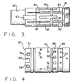
- FIG. 3 is an elevation view of the primary valve member utilized in the controller of FIG. 2.
- FIG. 4 is an elevation view of the follow-up valve member utilized in the controller of FIG. 2.
- FIG. 5 is an enlarged, fragmentary layout view showing the valving interface of the primary and follow-up valve members of FIGS. 3 and 4.
- FIG. 5a is a graph of orifice area versus valve displacement for the A1 and A5 orifices in the right turn condition.
- FIGS. 6 and 7 are graphs, taken during a steering wheel precession test, comparing steering wheel position versus steering cylinder position, with FIG. 6 representing a controller without the present invention and FIG. 7 representing a controller with the present invention.
- FIG. 1 illustrates schematically a typical hydraulic circuit of the type with which the present invention may be used.
- the circuit comprises a hydrostatic power steering system, generally designated 11, which is supplied with pressurized fluid by a pressure compensated, variable displacement pump 13, the compensator portion of which is shown only in schematic form, as its operation is well known in the art and forms no part of the present invention.
- the output from the pump 13 is fed to a steering control valve, generally designated 15, which is shown in greater detail in FIG. 2.
- the steering control valve 15 (controller) directs the flow of pressurized fluid to either the right end or the left end of a power steering cylinder 17 in response to rotation of a vehicle steering wheel (not shown) in the appropriate direction.
- Certain details of the controller 15 shown schematically in FIG. 1 will be referenced in connection with the subsequent description of FIGS. 2-4.
- the controller 15 which will be described only briefly herein, may be seen in greater detail, and its operation better understood, by reference to U.S. Patent No. 3,801,239 which is assigned to the assignee of the present invention, and incorporated herein by reference.
- the controller 15 is comprised of several sections, including a housing 19, a port plate 21, a fluid meter 23, and an end plate 25. These sections are held together in tight sealing engagement by means of a plurality of bolts 27 which are in threaded engagement with the housing 19.
- the housing 19 defines a fluid inlet port 29, a fluid return port 31, and a pair of control fluid ports 32 and 34 which, as shown in FIG. 1, are connected to the opposite ends of the cylinder 17.
- the housing 19 further defines four annular grooves 29g, 31g, 32g, and 34g, which are in open, relatively unrestricted fluid communication with the fluid ports 29, 31, 32, and 34, respectively.
- FIG. 1 Rotatably disposed within a valve bore 33 defined by the housing 19 is the valving shown schematically in FIG. 1, which comprises a primary, rotatable valve member 35 (spool) and a cooperating, relatively rotatable follow-up valve member 37 (sleeve).
- the forward end of the spool 35 includes a portion having a reduced diameter and defining a set of internal splines 39 which provide for a direct mechanical connection between the spool 35 and the steering wheel.
- the spool 35 and sleeve 37 will be described in greater detail subsequently.
- the fluid meter 23 in the subject embodiment, comprises a gerotor gear set including an internally toothed stator 41 and an externally toothed rotor 43.
- the rotor 43 defines a set of internal splines 45, and in splined engagement therewith is a set of external splines 47, formed at the rearward end of a drive shaft 49.
- the shaft 49 has a bifurcated forward end permitting driving connection between the shaft 49 and the sleeve 37 by means of a pin 51 passing through a pair of circumferentially-elongated pin openings 53 in the spool 35.
- pressurized fluid flowing through the valving in response to the turning of the spool 35 flows to the fluid meter 23 causing orbital and rotational movement of the rotor 43 (metering member) within the stator 41.
- Such movement of the rotor 43 causes follow-up movement of the sleeve 37 by means of the drive shaft 49 and pin 51, to maintain an appropriate relative displacement between the spool 35 and sleeve 37, for any particular rate of rotation of the steering wheel.
- a plurality of leaf springs 55 extending through spring openings 57 in the spool 35, urges the sleeve 37 toward the neutral position, relative to the spool 35.
- FIGS. 3 and 4 the spool 35 and sleeve 37 may be seen in greater detail. It should be noted that in FIGS. 3 and 4, the spool 35 and sleeve 37 are shown in their proper relative axial position, i.e., the right end surface of both lie in the same plane. In addition, the spool 35 and sleeve 37 are shown in their proper relative rotational position to define therebetween the neutral condition illustrated schematically in FIG. 1.
- the sleeve 37 defines a pair of diametrically-opposed openings 63 through which the leaf springs 55 extend radially outwardly.
- the sleeve 37 defines an annular groove 65 disposed axially to be in continuous fluid communication with the annular groove 29g.
- a plurality of ports 67 Disposed in fluid communication with the groove 65 is a plurality of ports 67 which, in the neutral position, have communication therethrough blocked by the outer surface of the spool 35.
- To the left of the annular groove 65 is a plurality of meter ports 69 which communicate between the valving and the expanding and contracting volume chambers of the fluid meter 23 by means of a plurality of axial bores defined by the housing 19 (not shown in FIG. 2).
- the sleeve 37 includes a portion 77 having a slightly reduced diameter, such that an annular passage is defined between the valve bore 33 and the reduced portion 77, which defines a plurality of tank openings 79.
- the spool 35 defines an annular groove 81, and in communication therewith, a plurality of axial slots 83.
- every other port 67 begins to communicate with the adjacent axial slot 83 to define therebetween a variable orifice, the composite of these individual variable orifices comprising a main variable flow control orifice A1-R or A1-L (see FIG. 1), depending upon the direction of rotation of the controller 15.
- Each of the axial slots 83 also communicates with one of the meter ports 69 to define therebetween a variable orifice, the composite of these individual variable orifices comprising a variable flow control orifice A2-R or A2-L, again depending upon the direction of rotation of the controller 15.
- Metered fluid returning from the fluid meter 23 flows through alternate ones of the meter ports 69 and enters an adjacent axial slot 85.
- the communication between the alternate meter ports 69 and each axial slot 85 defines a variable orifice, the composite of these individual orifices comprising a variable flow control orifice A3-R or A3-L, depending upon the direction of rotation.
- the axial slots 85 communicate with either the adjacent cylinder ports 73, or the adjacent cylinder ports 75, depending upon the direction of rotation of the steering wheel.
- each of the axial slots 85 communicates with an adjacent cylinder port 73 to define therebetween a variable orifice, the composite of these individual orifices comprising a variable cylinder control orifice A4-R.
- each of the axial slots 85 communicates with an adjacent cylinder port 75 to define therebetween a variable orifice, the composite of these individual variable orifices comprising a variable cylinder control orifice A4-L.
- each of the cylinder ports 75 communicates with the adjacent axial slot 87 to define therebetween a variable orifice, the composite of these individual orifices comprising a variable return flow control orifice A5-R.
- the cylinder ports 73 communicate with the adjacent axial slots 87 to define therebetween a variable orifice, the composite of these individual variable orifices comprising a return flow control orifice A5-L.
- each of the axial slots 87 communicates with one of the openings 79, such that this return fluid flows through the annular passage surrounding the portion 77, then through the annular groove 31g to the fluid return port 31, from where it flows back to the system reservoir (see FIG. 1).
- the above-described flow paths are typically referred to as the main fluid paths of the controller.
- the above-described difference in the length of leakage path for right and left turn conditions is related to the phenomenon of steering wheel precession.
- precession has been derived from the operating situation in which it is desired by the vehicle operator to steer a straight path, over a substantial distance, and it is observed by the operator that steering a straight path is not achieved by small deflections of the steering wheel about the centered position, but instead, in order to maintain the straight path, it is necessary to continually deflect the steering wheel further and further in one direction or the other. In other words, the steering wheel gradually "precesses” in one direction or the other.
- FIG. 6 there is illustrated a pair of graphs generated as part of a steering wheel precession test, with FIG. 6 representing a fluid controller not including the present invention.
- This test was performed with the steering wheel attached to a fixture, the purpose of which was to rotate the steering wheel by first turning it 35 degrees from neutral in the counterclockwise direction (descending portion of graph), then turning the wheel clockwise back toward neutral (ascending portion of graph) then past neutral 35 degrees .
- the centerline of the graph of steering wheel position is a horizontal, straight line, indicating, as expected, that the neutral position of the steering wheel remains constant.
- the lower graph illustrates the steering cylinder position, and it may be seen that during this particular precession test, the steering cylinder reciprocates about its "neutral" position in a pattern which generally corresponds to that of the steering wheel. In this particular wheel precession test, the steering cylinder reciprocated, during each cycle of the steering wheel, by an amount equal to about 81 mm (3.2 inches) on either side of the "neutral" position of the steering cylinder.
- the centerline of the graph of the steering cylinder position is not a horizontal line, as is desirable, but instead, is a gradually descending line. At the end of the approximately one minute precession test as represented in the graph of FIG.
- one or more of the axial slots 87 has a portion of its sidewall ground, or otherwise removed, as is generally indicated at 89, the ground portion being in a wall immediately adjacent a cylinder port 75.
- the result of the ground portion 89 is to advance the timing of the variable return flow control orifice A5-R, relative to the main variable flow control orifice A1-R, such that the orifice A5-R opens sooner than the orifice A1-R, rather than at substantially the same time as is typically the case.
- the orifices A1-R; A5-R; A1-L; and A5-L all began to open at 2.6 degrees of relative rotation between the spool 35 and sleeve 37.
- the orifice A5-R now begins to open at 2.3 degrees of relative rotation of the spool 35 and sleeve 37.
- fluid begins to flow sooner from the main flow path back to the system reservoir, in a right turn condition, compensating for the fact that the length of the leakage path is longer for a right turn condition.
- FIG. 7 there is illustrated a pair of graphs similar to those illustrated in FIG. 6.
- the test procedure for the wheel precession test of FIG. 7 was identical to that for FIG. 6, and again, the upper graph illustrates the steering wheel position, while the lower graph illustrates the steering cylinder position.
- the centerline of the graph of steering wheel position is a horizontal, straight line because the neutral position of the steering wheel remains constant in the test procedure.
- utilizing the present invention results in a substantially different graph for the steering cylinder than in FIG. 6, without the present invention.
- the graph of steering cylinder position again corresponds generally to the graph of steering wheel position, but with the invention the centerline remains substantially horizontal.
- the graph indicates that at the end of the one minute test cycle, by using a controller including the present invention, the steering cylinder "neutral" position had changed about 7.1 mm (.28 inches) from its initial position, compared with a change of 41 mm (1.6 inches) using a controller not including the present invention.
- the use of the present invention reduced the change in steering cylinder position (which is the same as reducing steering wheel precession) by 82 percent in the particular wheel procedure represented by the graphs of FIGS. 6 and 7.
- the preferred embodiment of the subject invention involves the provision of the ground portion 89 to advance the timing of the return flow control orifice A5-R
- the same result can be accomplished in various other ways.
- one or more of the cylinder ports 75 could have its size or shape changed to achieve the object of advancing the timing of the orifice A5-R.
- the object of the invention could be achieved by delaying the timing of the return flow control orifice A5-L, relative to that of the orifice A5-R, and it is believed that substantially the same result as illustrated in the graphs of FIGS. 6 and 7 could be achieved.
- the present invention has been described in connection with a controller of the type in which the main orifice Al and the return orifice A5 normally open at the same time, it will be understood by those skilled in the art that there are various controller designs in which the return orifice A-5 typically opens somewhat later than the main orifice Al.
- the object of the invention could be achieved by advancing the timing of the return flow control orifice A5-R, relative to the orifice A5-L, such that the orifice A5-R opens at about the same time as the main orifice A1-R, or just slightly thereafter.
Landscapes
- Engineering & Computer Science (AREA)
- Chemical & Material Sciences (AREA)
- Combustion & Propulsion (AREA)
- Transportation (AREA)
- Mechanical Engineering (AREA)
- Power Steering Mechanism (AREA)
Claims (9)
- Steuergerät (15) zum Steuern des Fluidstromes von einer Druckfluidquelle (13) zu einer fluidbetätigten Vorrichtung (17); wobei das Steuergerät versehen ist mit einer Gehäuseanordnung (19), die einen Einlaß (29) zum Anschluß an die Druckfluidquelle, einen Rücklaufanschluß (31) sowie einen ersten (32) und einen zweiten (34) Steuerfluiddurchlaß zum Anschluß an die fluiddruckbetätigte Vorrichtung bildet; mit einer Ventilanordnung, die in der Gehäuseanordnung angeordnet ist und ein drehbares Hauptventilorgan (35) und ein relativ drehbares Nachlaufventilorgan (37) aufweist, wobei die Ventilorgane eine Neutralstellung sowie eine erste und eine zweite Arbeitsstellung bestimmen, wobei in der ersten Arbeitsstellung die Gehäuseanordnung und die Ventilanordnung zusammen einen ersten Hauptfluidweg bilden, der für eine Fluidverbindung von dem Einlaß zu dem ersten Steuerfluiddurchlaß und von dem zweiten Steuerfluiddurchlaß zu dem Rücklaufdurchlaß sorgt, und wobei in der zweiten Arbeitsstellung die Gehäuseanordnung und die Ventilanordnung zusammen einen zweiten Hauptfluidweg bilden, der für eine Fluidverbindung von dem Einlaß zu dem zweiten Steuerfluiddurchlaß und von dem ersten Steuerfluiddurchlaß zu dem Rücklaufdurchlaß sorgt; mit einer fluidbetätigten Einrichtung (23), welche das Nachlaufventilorgan (37) in Abhängigkeit von dem Fluidstrom durch den ersten oder den zweiten Hauptfluidweg zu einer Nachlaufbewegung veranlaßt; wobei der erste und der zweite Hauptfluidweg eine erste (A1-R) bzw. eine zweite (A1-L) verstellbare Hauptstromsteueröffnung bilden, die in Richtung auf ein axiales Ende der Ventilanordnung angeordnet sind, wobei eine Verbindung zwischen der Ventilanordnung und dem Rücklaufdurchlaß in Richtung auf das andere axiale Ende der Ventilanordnung stattfindet; wobei der erste Hauptfluidweg eine zwischen der fluidbetätigten Einrichtung (23) und dem ersten Steuerfluiddurchlaß (32) liegende erste verstellbare Zylindersteueröffnung (A4-R) bildet und der zweite Hauptfluidweg eine zwischen der fluidbetätigten Einrichtung (23) und dem zweiten Steuerfluiddurchlaß (34) liegende zweite verstellbare Zylindersteueröffnung (A4-L) bildet, wobei die erste verstellbare Zylindersteueröffnung von dem anderen axialen Ende der Ventilanordnung axial weiter entfernt liegt als die zweite verstellbare Zylindersteueröffnung; wobei der erste Hauptfluidweg eine zwischen dem zweiten Steuerfluiddurchlaß und dem Rücklaufdurchlaß liegende erste verstellbare Rücklaufstromsteueröffnung (A5-R) bildet und der zweite Hauptfluidweg eine zwischen dem ersten Steuerfluiddurchlaß und dem Rücklaufdurchlaß liegende zweite verstellbare Rücklaufstromsteueröffnung (A5-L) bildet; dadurch gekennzeichnet, daß:a) die erste verstellbare Rücklaufstromsteueröffnung (A5-R) so angeordnet ist, daß sie sich bei einem Verdrehen um X Grad zu öffnen beginnt, wenn die Ventilorgane von der Neutralstellung in Richtung auf die erste Arbeitsstellung verstellt werden;b) daß die zweite verstellbare Rücklaufstromsteueröffnung (A5-L) so angeordnet ist, daß sie sich bei einem Verdrehen um Y Grad zu öffnen beginnt, wenn die Ventilorgane von der Neutralstellung in Richtung auf die zweite Arbeitsstellung verstellt werden;c) wobei X Grad kleiner als Y Grad ist, wodurch der erste Hauptfluidweg mit dem Rücklaufdurchlaß früher als der zweite Hauptfluidweg in Verhindung zu kommen beginnt, um eine Kompensation für ungleiche Leckwege zu erreichen, die dadurch verursacht werden, daß die erste verstellbare Zylindersteueröffnung (A4-R) von dem anderen axialen Ende der Ventilanordnung weiter entfernt liegt als die zweite verstellbare Zylindersteueröffnung (A4-L).
- Steuergerät nach Anspruch 1, dadurch gekennzeichnet, daß das relativ drehbare Nachlaufventilorgan (37) ein hohles, im wesentlichen zylindrisches hülsenförmiges Ventilorgan aufweist, welches das Hauptventilorgan (35) umgibt.
- Steuergerät nach Anspruch 2, dadurch gekennzeichnet, daß das drehbare Hauptventilorgan (35) ein hohles, im wesentlichen zylindrisches trommelförmiges Ventilorgan aufweist.
- Steuergerät nach Anspruch 3, dadurch gekennzeichnet, daß das Hauptventilorgan eine erste Mehrzahl von axial gerichteten Schlitzen (85) bildet, die in der Außenumfangsfläche des Ventilorgans ausgebildet sind, und daß das Nach-lauf-ventilorgan eine erste Mehrzahl von Durchlässen (73) bildet, von denen sich jeder radial durch das hülsenförmige Ventilorgan hindurch erstreckt.
- Steuergerät nach Anspruch 4, dadurch gekennzeichnet, daß die erste Mehrzahl von axial gerichteten Schlitzen (85) dosiertes Fluid enthält, das durch die fluidbetätigte Einrichtung (23) hindurchgeströmt ist, wobei eine Verstellung der Ventilanordnung in Richtung auf die erste Arbeitsstellung zu einer Überlappung der ersten Mehrzahl von axial gerichteten Schlitzen und der ersten Mehrzahl von Durchlässen (73) führt, und wobei diese Überlappungen zusammen die erste verstellbare Zylindersteueröffnung (A4-R) bilden.
- Steuergerät nach Anspruch 5, dadurch gekennzeichnet, daß das Nachlaufventilorgan (37) eine zweite Mehrzahl von Durchlässen (75) bildet, von denen jeder axial durch das hülsenförmige Ventilorgan hindurchreicht, wobei die zweite Mehrzahl von Durchlässen axial zwischen der ersten Mehrzahl von Durchlässen (73) und dem anderen axialen Ende der Ventilanordnung ausgebildet ist, wodurch eine Verstellung der Ventilanordnung in Richtung auf die zweite Arbeitsstellung zu einer Überlappung der ersten Mehrzahl von axial gerichteten Schlitzen (85) und der zweiten Mehrzahl von Durchlässen führt, und wobei diese Überlappungen zusammen die zweite verstellbare Zylindersteueröffnung (A4-L) bilden.
- Steuergerät nach Anspruch 6, dadurch gekennzeichnet, daß das Hauptventilorgan eine zweite Mehrzahl von axial gerichteten Schlitzen (87) bildet, die an der Außenumfangsfläche des Ventilorgans angeordnet sind und die mit dem Rücklaufdurchlaß (31) in Strömungsverbindung stehen.
- Steuergerät nach Anspruch 7, dadurch gekennzeichnet, daß eine Verstellung der Ventilanordnung in Richtung auf die erste Arbeitsstellung zu einer Überlappung der zweiten Mehrzahl von axial gerichteten Schlitzen (87) und der zweiten Mehrzahl von Durchlässen (75) führt, wobei diese Überlappungen gemeinsam die erste verstellbare Rücklaufstromsteueröffnung (A5-R) bilden.
- Steuergerät nach Anspruch 8, dadurch gekennzeichnet, daß eine Verstellung der Ventilanordnung in Richtung auf die zweite Arbeitsstellung zu einer Überlappung der zweiten Mehrzahl von axial gerichteten Schlitzen (87) und der ersten Mehrzahl von Durchlässen (73) führt und diese Überlappungen zusammen die zweite verstellbare Rücklaufstromsteueröffnung (A5-L) bilden.
Applications Claiming Priority (2)
| Application Number | Priority Date | Filing Date | Title |
|---|---|---|---|
| US07/252,619 US4827978A (en) | 1988-10-03 | 1988-10-03 | Fluid controller with reduced steering wheel precession |
| US252619 | 1999-02-16 |
Publications (3)
| Publication Number | Publication Date |
|---|---|
| EP0362597A2 EP0362597A2 (de) | 1990-04-11 |
| EP0362597A3 EP0362597A3 (en) | 1990-09-19 |
| EP0362597B1 true EP0362597B1 (de) | 1993-01-20 |
Family
ID=22956800
Family Applications (1)
| Application Number | Title | Priority Date | Filing Date |
|---|---|---|---|
| EP19890117145 Expired - Lifetime EP0362597B1 (de) | 1988-10-03 | 1989-09-15 | Hydraulisches Ventil mit verminderter Präzession des Lenkrades |
Country Status (5)
| Country | Link |
|---|---|
| US (1) | US4827978A (de) |
| EP (1) | EP0362597B1 (de) |
| JP (1) | JP2721920B2 (de) |
| DE (1) | DE68904515T2 (de) |
| DK (1) | DK169170B1 (de) |
Families Citing this family (3)
| Publication number | Priority date | Publication date | Assignee | Title |
|---|---|---|---|---|
| US4958493A (en) * | 1988-10-06 | 1990-09-25 | Eaton Corporation | Open-center steering control unit with flow amplification |
| USRE34746E (en) * | 1988-10-06 | 1994-10-04 | Eaton Corporation | Open-center steering control unit with flow amplification |
| US20020179161A1 (en) * | 2001-05-30 | 2002-12-05 | Eaton Corporation | Low slip steering system and improved fluid controller therefor |
Family Cites Families (5)
| Publication number | Priority date | Publication date | Assignee | Title |
|---|---|---|---|---|
| US3801239A (en) | 1972-04-03 | 1974-04-02 | Eaton Corp | Controller for fluid operated device |
| US4037620A (en) * | 1976-04-23 | 1977-07-26 | Eaton Corporation | Controller for fluid pressure operated devices |
| DE2702692C2 (de) * | 1977-01-24 | 1984-05-24 | Danfoss A/S, Nordborg | Steuergerät für hydrostatische Hilfskraftlenkeinrichtungen |
| US4212229A (en) * | 1978-10-25 | 1980-07-15 | Eaton Corporation | Controller for fluid pressure operated devices |
| DE3604129A1 (de) * | 1986-02-10 | 1987-08-13 | Danfoss As | Drehschieber-ventilanordnung fuer das steuergeraet einer hydrostatischen lenkeinrichtung |
-
1988
- 1988-10-03 US US07/252,619 patent/US4827978A/en not_active Expired - Lifetime
-
1989
- 1989-09-15 DE DE8989117145T patent/DE68904515T2/de not_active Expired - Fee Related
- 1989-09-15 EP EP19890117145 patent/EP0362597B1/de not_active Expired - Lifetime
- 1989-10-02 DK DK484189A patent/DK169170B1/da active IP Right Grant
- 1989-10-03 JP JP25862189A patent/JP2721920B2/ja not_active Expired - Fee Related
Also Published As
| Publication number | Publication date |
|---|---|
| DK484189A (da) | 1990-04-04 |
| EP0362597A2 (de) | 1990-04-11 |
| DK169170B1 (da) | 1994-09-05 |
| DE68904515T2 (de) | 1993-05-19 |
| US4827978A (en) | 1989-05-09 |
| DK484189D0 (da) | 1989-10-02 |
| JPH02127165A (ja) | 1990-05-15 |
| EP0362597A3 (en) | 1990-09-19 |
| JP2721920B2 (ja) | 1998-03-04 |
| DE68904515D1 (de) | 1993-03-04 |
Similar Documents
| Publication | Publication Date | Title |
|---|---|---|
| US4759182A (en) | Steering control unit with flow amplification | |
| EP0038542B1 (de) | Druckmittelbetätigtes Steuergerät | |
| US4109679A (en) | Controller for fluid pressure operated devices | |
| US4167893A (en) | Load sensing valve | |
| US3960234A (en) | Controller for fluid pressure operated devices providing high pressure to an auxiliary device | |
| US4676334A (en) | Power steering system with hydraulic reaction | |
| EP1153818B1 (de) | Durchflussregler mit Dosierpumpen-Umgehungsleitung | |
| US4804016A (en) | Fluid controller with improved pressure balancing | |
| US4781219A (en) | Fluid controller and dampening fluid path | |
| US4862690A (en) | Steering control unit with both flow amplification and manual steering capability | |
| US4799514A (en) | Rotary servovalve for power-assisted steering system | |
| US5582207A (en) | Steering control valve with flow gaps which change relative size for noise suppression | |
| US4558720A (en) | Closed-center controller for use with unequal area cylinder | |
| US4488569A (en) | Apparatus with staged pressure differential for controlling fluid flow | |
| US4212229A (en) | Controller for fluid pressure operated devices | |
| US5638864A (en) | Steering control unit with flow amplification for unequal area cylinder | |
| EP0362597B1 (de) | Hydraulisches Ventil mit verminderter Präzession des Lenkrades | |
| US4050474A (en) | Controller for fluid pressure operated devices providing high pressure to an auxiliary device | |
| EP0592095B1 (de) | Steuerventil mit abgeschrägten Steuerflächen für eine Lenkung | |
| EP0728654B1 (de) | Servolenkungsventil mit Strömungsöffnungen von unterschiedlicher Grösse zur Geräuschunterdrückung | |
| KR930002434B1 (ko) | 스티어링기어비가변장치 | |
| US4779646A (en) | Fluid flow control valve | |
| EP0264613B1 (de) | Flüssigkeitssteuerung und gedämpfter Flüssigkeitsweg | |
| US5937728A (en) | Power steering control valve with noise reduction | |
| US3957129A (en) | Steering system |
Legal Events
| Date | Code | Title | Description |
|---|---|---|---|
| PUAI | Public reference made under article 153(3) epc to a published international application that has entered the european phase |
Free format text: ORIGINAL CODE: 0009012 |
|
| AK | Designated contracting states |
Kind code of ref document: A2 Designated state(s): DE FR GB IT |
|
| PUAL | Search report despatched |
Free format text: ORIGINAL CODE: 0009013 |
|
| AK | Designated contracting states |
Kind code of ref document: A3 Designated state(s): DE FR GB IT |
|
| 17P | Request for examination filed |
Effective date: 19901231 |
|
| 17Q | First examination report despatched |
Effective date: 19910905 |
|
| GRAA | (expected) grant |
Free format text: ORIGINAL CODE: 0009210 |
|
| AK | Designated contracting states |
Kind code of ref document: B1 Designated state(s): DE FR GB IT |
|
| ITF | It: translation for a ep patent filed | ||
| REF | Corresponds to: |
Ref document number: 68904515 Country of ref document: DE Date of ref document: 19930304 |
|
| ET | Fr: translation filed | ||
| PLBE | No opposition filed within time limit |
Free format text: ORIGINAL CODE: 0009261 |
|
| STAA | Information on the status of an ep patent application or granted ep patent |
Free format text: STATUS: NO OPPOSITION FILED WITHIN TIME LIMIT |
|
| 26N | No opposition filed | ||
| REG | Reference to a national code |
Ref country code: GB Ref legal event code: IF02 |
|
| PGFP | Annual fee paid to national office [announced via postgrant information from national office to epo] |
Ref country code: GB Payment date: 20040812 Year of fee payment: 16 |
|
| PGFP | Annual fee paid to national office [announced via postgrant information from national office to epo] |
Ref country code: FR Payment date: 20040902 Year of fee payment: 16 |
|
| PGFP | Annual fee paid to national office [announced via postgrant information from national office to epo] |
Ref country code: DE Payment date: 20040930 Year of fee payment: 16 |
|
| PG25 | Lapsed in a contracting state [announced via postgrant information from national office to epo] |
Ref country code: IT Free format text: LAPSE BECAUSE OF NON-PAYMENT OF DUE FEES Effective date: 20050915 Ref country code: GB Free format text: LAPSE BECAUSE OF NON-PAYMENT OF DUE FEES Effective date: 20050915 |
|
| PG25 | Lapsed in a contracting state [announced via postgrant information from national office to epo] |
Ref country code: DE Free format text: LAPSE BECAUSE OF NON-PAYMENT OF DUE FEES Effective date: 20060401 |
|
| GBPC | Gb: european patent ceased through non-payment of renewal fee |
Effective date: 20050915 |
|
| PG25 | Lapsed in a contracting state [announced via postgrant information from national office to epo] |
Ref country code: FR Free format text: LAPSE BECAUSE OF NON-PAYMENT OF DUE FEES Effective date: 20060531 |
|
| REG | Reference to a national code |
Ref country code: FR Ref legal event code: ST Effective date: 20060531 |