EP0362608A2 - Dispositif d'alarme lumineux - Google Patents
Dispositif d'alarme lumineux Download PDFInfo
- Publication number
- EP0362608A2 EP0362608A2 EP89117191A EP89117191A EP0362608A2 EP 0362608 A2 EP0362608 A2 EP 0362608A2 EP 89117191 A EP89117191 A EP 89117191A EP 89117191 A EP89117191 A EP 89117191A EP 0362608 A2 EP0362608 A2 EP 0362608A2
- Authority
- EP
- European Patent Office
- Prior art keywords
- optical fiber
- motor vehicle
- warning device
- display matrix
- light warning
- Prior art date
- Legal status (The legal status is an assumption and is not a legal conclusion. Google has not performed a legal analysis and makes no representation as to the accuracy of the status listed.)
- Granted
Links
- 239000013307 optical fiber Substances 0.000 claims abstract description 68
- 239000011159 matrix material Substances 0.000 claims abstract description 31
- 230000001105 regulatory effect Effects 0.000 claims abstract description 4
- 230000000977 initiatory effect Effects 0.000 claims abstract description 3
- 238000010276 construction Methods 0.000 claims description 13
- 230000003287 optical effect Effects 0.000 claims description 2
- 230000004907 flux Effects 0.000 description 1
- 229910052736 halogen Inorganic materials 0.000 description 1
- 150000002367 halogens Chemical class 0.000 description 1
- 230000008447 perception Effects 0.000 description 1
Images



Classifications
-
- B—PERFORMING OPERATIONS; TRANSPORTING
- B60—VEHICLES IN GENERAL
- B60Q—ARRANGEMENT OF SIGNALLING OR LIGHTING DEVICES, THE MOUNTING OR SUPPORTING THEREOF OR CIRCUITS THEREFOR, FOR VEHICLES IN GENERAL
- B60Q7/00—Arrangement or adaptation of portable emergency signal devices on vehicles
- B60Q7/02—Arrangement or adaptation of portable emergency signal devices on vehicles to be attached to overhanging loads or extending parts of vehicle
-
- B—PERFORMING OPERATIONS; TRANSPORTING
- B60—VEHICLES IN GENERAL
- B60Q—ARRANGEMENT OF SIGNALLING OR LIGHTING DEVICES, THE MOUNTING OR SUPPORTING THEREOF OR CIRCUITS THEREFOR, FOR VEHICLES IN GENERAL
- B60Q1/00—Arrangement of optical signalling or lighting devices, the mounting or supporting thereof or circuits therefor
- B60Q1/26—Arrangement of optical signalling or lighting devices, the mounting or supporting thereof or circuits therefor the devices being primarily intended to indicate the vehicle, or parts thereof, or to give signals, to other traffic
- B60Q1/2611—Indicating devices mounted on the roof of the vehicle
-
- B—PERFORMING OPERATIONS; TRANSPORTING
- B60—VEHICLES IN GENERAL
- B60Q—ARRANGEMENT OF SIGNALLING OR LIGHTING DEVICES, THE MOUNTING OR SUPPORTING THEREOF OR CIRCUITS THEREFOR, FOR VEHICLES IN GENERAL
- B60Q1/00—Arrangement of optical signalling or lighting devices, the mounting or supporting thereof or circuits therefor
- B60Q1/26—Arrangement of optical signalling or lighting devices, the mounting or supporting thereof or circuits therefor the devices being primarily intended to indicate the vehicle, or parts thereof, or to give signals, to other traffic
- B60Q1/30—Arrangement of optical signalling or lighting devices, the mounting or supporting thereof or circuits therefor the devices being primarily intended to indicate the vehicle, or parts thereof, or to give signals, to other traffic for indicating rear of vehicle, e.g. by means of reflecting surfaces
- B60Q1/301—Arrangement of optical signalling or lighting devices, the mounting or supporting thereof or circuits therefor the devices being primarily intended to indicate the vehicle, or parts thereof, or to give signals, to other traffic for indicating rear of vehicle, e.g. by means of reflecting surfaces by means of surfaces, e.g. metal plate, reflecting the light of an external light source
- B60Q1/3015—Arrangement of optical signalling or lighting devices, the mounting or supporting thereof or circuits therefor the devices being primarily intended to indicate the vehicle, or parts thereof, or to give signals, to other traffic for indicating rear of vehicle, e.g. by means of reflecting surfaces by means of surfaces, e.g. metal plate, reflecting the light of an external light source combined with a lamp
-
- E—FIXED CONSTRUCTIONS
- E01—CONSTRUCTION OF ROADS, RAILWAYS, OR BRIDGES
- E01F—ADDITIONAL WORK, SUCH AS EQUIPPING ROADS OR THE CONSTRUCTION OF PLATFORMS, HELICOPTER LANDING STAGES, SIGNS, SNOW FENCES, OR THE LIKE
- E01F9/00—Arrangement of road signs or traffic signals; Arrangements for enforcing caution
- E01F9/60—Upright bodies, e.g. marker posts or bollards; Supports for road signs
- E01F9/658—Upright bodies, e.g. marker posts or bollards; Supports for road signs characterised by means for fixing
- E01F9/662—Upright bodies, e.g. marker posts or bollards; Supports for road signs characterised by means for fixing mounted on vehicles, e.g. service vehicles; Warning vehicles travelling along with road-maintenance, e.g. remotely controlled
Definitions
- the invention relates to a light warning device with a warning control panel for regulating road traffic, which is mounted in the region of the rear of a vehicle in a vertical position and on which traffic signs for subsequent traffic can be represented by means of controllable, electrical lighting elements.
- a light warning device of this type is known from DE-PS 34 34 34341.
- This known light warning device has a vertical panel with colored strips and electric lamps mounted thereon in the shape of an arrow. There is also a normal traffic sign in the lower part of the board.
- the lamps are attached to a rotatable arrow-shaped support, so that the arrow can be adjusted to the bottom left and to the bottom right.
- the vehicle is designed as a trailer and can be coupled to a motor vehicle, which can then take over the supply and control of the light warning device.
- warning devices of this type are set up on construction sites and fed directly from the AC network via installed power supply cables.
- the warning board is designed as a controllable optical fiber display matrix with a plurality of traffic signs and is attached or can be attached to the roof of a motor vehicle which runs right through to the rear, in that it is powered by the motor vehicle or by an additional motor vehicle.
- Power supply is fed or feedable that in the area of the dashboard of the motor vehicle a control panel is arranged or built into it, which has control elements for switching the light warning device on and off and for initiating the display of different traffic signs on the optical fiber display matrix and that the control panel which Power supply and the optical fiber display matrix are connected or connectable to one another via connecting cables laid in the motor vehicle.
- the light warning device itself is designed as a motor vehicle and can therefore easily follow any heavy load transport.
- the displayed traffic signs are at a great distance from the road, so that they are also good in a queue of motor vehicles further away can be perceived.
- the entire control and power supply is integrated in the motor vehicle, so that the light warning device represents an autonomous, mobile unit that is ready for use at any time.
- the use of an optical fiber display matrix in the simplest way opens up the representation of a number of traffic signs true to the original, such as direction arrows, speed limit signs and the like, which can also be adapted to the traffic situation at any time by the driver of the motor vehicle while driving. All that is required is appropriate control signals that can easily be given by the control panel arranged or installed in the area of the dashboard.
- the display of different traffic signs on the warning board is achieved simply by the fact that the optical fiber display matrix has a plurality of optical fiber bundles which can be illuminated by individually controllable light sources and that the free ends of the individual in the position assigned to different traffic signs in the area of the optical fiber display matrix Optical fibers of the optical fiber bundle end.
- the construction of the optical fiber display matrix is such that the optical fiber display matrix consists of a perforated grid plate with light-emitting halftone dots, each of which can be connected to one end of an optical fiber, that the optical fibers are assigned to a traffic sign or a color of the traffic sign are combined to form an optical fiber bundle that can be individually illuminated and that individual optical sources and / or color filters are assigned to the optical fiber bundles.
- the optical fiber display matrix is accommodated in a housing that is articulated transversely to the vehicle axis on a roof stand construction that can be connected to the motor vehicle and that can be folded down onto the roof towards the front of the vehicle, then the optical fiber display matrix can be brought into a storage position in the simplest way in which it is no longer visible.
- a spoiler is articulated on the roof stand structure of the joint axis of the carrier, which spoiler covers the optical fiber display matrix folded down on the roof both in the working position and in the folded-down position, the cross section being different tapered towards the front of the vehicle.
- an embodiment is advantageous which is characterized in that the optical fiber display matrix with the roof stand construction and the spoiler is firmly connected to the motor vehicle and that the connecting lines are fixed in the motor vehicle and are permanently connected .
- a light warning device 10 is shown with an optical fiber display matrix 12 as for regulating road traffic.
- the optical fiber display matrix 12 is arranged on the back of a motor vehicle 14 traveling in the direction of travel 15 in a vertical position and can be used for subsequent traffic Represent traffic signs 17 and 18 by means of controllable lighting elements.
- the light warning device 10 is accommodated in a housing 20, on the upper and horizontally running edge of which two further signal devices 21 and 22 are arranged.
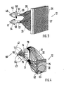
- the optical fiber display matrix 12 consists of a perforated grid plate 25 (here matrix) with light-emitting grid points 27 and 28, in which the one ends of optical fibers 29 to 32 are arranged.
- the other ends of the optical fibers 29 to 32 are illuminated by light sources 40 to 43 (here halogen lamps).
- Optical fibers 29 and 30, which are assigned to a traffic sign in the perforated plate 25, are combined to form a multi-arm optical fiber bundle 50 and 51.
- the light sources 40 and 41 are each in a concave mirror 54 and 55, so that the emitted light falls directly on the ends 57 and 58 of the optical fiber bundles 50 and 51.
- 3 shows that a light filter 60 is arranged between the light source 40 and the end 57 of the optical fiber bundle 50.
- the symbol shown on the perforated grid plate (here the number 6) consists of groups of two 62, 63 of grid points, such that the one grid point of groups of two 62 and 63 belongs to the first optical fiber bundle 70 , while the other grid point of the groups of two 62 and 63 belongs to the second optical fiber bundle 71.
- the two free ends 74 and 75 of the optical fiber bundles 70 and 71 are illuminated by the light sources 42 and 43.
- the two free ends 74 and 75 of the optical fiber bundles 70 and 71 are in one Lighting unit 80 connected, which consists of the two light sources 42 and 43.
- the lighting unit 80 consists of a housing, in the interior of which two concave mirrors 81 and 82 are arranged and which is provided with connecting sockets 84 and 85 for the optical fiber bundles, not shown.
- the concave mirror 81 is arranged coaxially to the connection socket 84, while the concave mirror 82 runs coaxially with the connection socket 85.
- the axes 87 and 88 of the concave mirrors 81 and 82 define a common plane and intersect at an angle of 90 °. It can be seen that the light source 90 is a point source, which are each arranged in the focal point of the concave mirror 81 and 82, respectively.
- a semitransparent mirror 96 which is arranged at right angles to the plane defined by the two axes 87 and 88 and is cut by the axes 87 and 88 at an angle of 45 °.
- 50% of the luminous flux of the two point light sources reaches the entry surfaces 74 and 75 of the optical fiber bundles, which are not shown, which form the symbol. If one point light source fails, the other point light source 90 is switched on, which illuminate the two optical fiber bundles 70 and 71 in the same way.
- the display multicolored in such a way that a corresponding color filter is placed in front of the entry surface of one of the two optical fiber bundles 74 and 75. If particularly high light intensities are required, for example in fog, the character brightness can be doubled by switching on both point light sources at the same time.
- the lighting unit 80 as shown in FIGS. 5, 6 and 7, can be combined to form a lighting column, which is then arranged in the housing 20. 5, 6 and 7 also show that the point light sources 90 are arranged in sockets 100 and are held by prestressed spring bodies 102. The spring bodies 102 are connected to the lighting unit 80 by means of rivets 103.
- FIG. 3 shows that the ends of the optical fibers 29 and 39 are arranged in the grid plate 25 in such a way that a two-color traffic sign or two different traffic signs can be represented (cf. also FIG. 2).
- the ends of the optical fibers 29, 30 or 31 and 32 that extend into the perforated grid plate 25 expand conically towards their ends and are arranged sunk in the individual holes of the perforated grid plate 25.
- the grid points 27 and 28 have a diameter of approximately 4 mm.
- the optical fibers 29, 30 and 31, 32 are connected by means of expansion sleeves, not shown.
- the optical fibers 29 and 30 can be distributed over the entire perforated grid plate 25, while in the case of two different traffic signs the optical fibers 29 and 30 are distributed over divided areas of the perforated grid plate 25.
- the lighting units shown in FIGS. 5, 6 and 7 are vibration-free with the housing 20 and connected to the interior of the motor vehicle via electrical connecting lines 16 and 19. From there, the lighting units or the lighting column can be controlled via the control panel 13, which can be installed in the dashboard.
- the supply can Via the power supply 11 of the motor vehicle 14 or an additional power supply, which is also accommodated in the motor vehicle 14.
- the connecting lines 16 and 19 connect the control panel 13, the power supply 11 and the optical fiber display matrix 12 to one another.
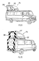
- the optical fiber display matrix 12 can be permanently connected to the motor vehicle 14 and the connecting lines 16 and 19 can also be permanently installed and switched on in the motor vehicle 14 (FIG. 2).
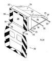
- FIG. 8 shows a light warning device 200 designed as a variable message sign, which is arranged in a carrier 202 and is supported by a roof stand construction consisting of struts 190, 191 and 210 to 213.
- This roof stand construction can be detachably connected to the roof of the motor vehicle.
- the light warning device 200 is connected to a spoiler 214. Both the spoiler 214 and the light warning device 200 are connected to the roof stand construction in an articulated manner about the hinge axes 217 and 220 with the roof stand construction.
- the Articulated axis 220 is designed such that the light warning device 200 can be displaced transversely to the direction of travel of the motor vehicle 14 and can thereby be ascertained.
- the spoiler 214 has an approximately flat section 216 which merges into an arcuate section 215.
- the free ends of the struts 190 and 191 are connected via joints 204 and 205 to a plate 203 having openings. This plate at least partially covers the rear of the vehicle (see FIGS. 10 and 12).
- the section 206 of the light warning device which represents the traffic switches is, in terms of light emission, similar or identical to the optical fiber display matrix 12 shown in FIGS. 3 and 4.
- the spoiler 214 can be folded around the hinge axis 217 in the region of the support rods 223.
- the light warning device shown in Fig. 8 is in the working position.
- an adjusting rod 222 is provided, one end of which is articulated to the roof stand construction, while the other end is adjustable in a vertically extending groove 221, which is formed on the rear side of the light warning device 200.
- FIGS. 11 and 12 show the light warning device 200 in the storage position. It lies with its back on the roof frame construction and is covered by the spoiler 214.
- a servomotor not shown, is provided for the retraction and extension of the light warning device 200, so that the entire operation can be carried out from the driver's cabin of the motor vehicle 14 via the control panel 13 installed in the dashboard.
Landscapes
- Engineering & Computer Science (AREA)
- Mechanical Engineering (AREA)
- Architecture (AREA)
- Civil Engineering (AREA)
- Structural Engineering (AREA)
- Lighting Device Outwards From Vehicle And Optical Signal (AREA)
- Traffic Control Systems (AREA)
- Illuminated Signs And Luminous Advertising (AREA)
- Emergency Alarm Devices (AREA)
- Push-Button Switches (AREA)
- Burglar Alarm Systems (AREA)
- Alarm Systems (AREA)
- Road Signs Or Road Markings (AREA)
Priority Applications (2)
| Application Number | Priority Date | Filing Date | Title |
|---|---|---|---|
| AT89117191T ATE76369T1 (de) | 1988-10-01 | 1989-09-16 | Lichtwarnvorrichtung. |
| DE8916120U DE8916120U1 (de) | 1988-10-01 | 1989-09-16 | Lichtwarnvorrichtung |
Applications Claiming Priority (2)
| Application Number | Priority Date | Filing Date | Title |
|---|---|---|---|
| DE3833544 | 1988-10-01 | ||
| DE3833544 | 1988-10-01 |
Publications (4)
| Publication Number | Publication Date |
|---|---|
| EP0362608A2 true EP0362608A2 (fr) | 1990-04-11 |
| EP0362608A3 EP0362608A3 (en) | 1990-08-08 |
| EP0362608B1 EP0362608B1 (fr) | 1992-05-20 |
| EP0362608B2 EP0362608B2 (fr) | 1996-04-24 |
Family
ID=6364253
Family Applications (1)
| Application Number | Title | Priority Date | Filing Date |
|---|---|---|---|
| EP89117191A Expired - Lifetime EP0362608B2 (fr) | 1988-10-01 | 1989-09-16 | Dispositif d'alarme lumineux |
Country Status (5)
| Country | Link |
|---|---|
| US (1) | US5010319A (fr) |
| EP (1) | EP0362608B2 (fr) |
| AT (1) | ATE76369T1 (fr) |
| CA (1) | CA1298256C (fr) |
| DE (1) | DE58901489D1 (fr) |
Cited By (4)
| Publication number | Priority date | Publication date | Assignee | Title |
|---|---|---|---|---|
| FR2742176A1 (fr) * | 1995-12-11 | 1997-06-13 | Crapie Sa | Fleche de signalisation lumineuse a geometrie variable |
| DE10132998A1 (de) * | 2001-07-06 | 2002-09-26 | Schott Glas | Kantenbeleuchtete Informationstafeln für Lastkraftwagen |
| DE102006043472A1 (de) * | 2006-09-15 | 2008-03-27 | Hella Kgaa Hueck & Co. | Signalgeber für Fahrzeuge |
| EP4372716A1 (fr) * | 2022-11-18 | 2024-05-22 | Helga Sommer | Procédé d'actionnement d'au moins une unité de sortie, système de signalisation pour au moins un véhicule compagnon, véhicule compagnon et ensemble de véhicules |
Families Citing this family (28)
| Publication number | Priority date | Publication date | Assignee | Title |
|---|---|---|---|---|
| US5111183A (en) * | 1991-03-28 | 1992-05-05 | Frank Wang | Third brake lamp employing optical fibers |
| US5532711A (en) * | 1991-09-27 | 1996-07-02 | Inwave Corporation | Lightweight display systems and methods for making and employing same |
| US5400225A (en) * | 1993-10-06 | 1995-03-21 | Currie; Joseph E. | Optical fiber illumination device |
| US5563588A (en) * | 1994-08-02 | 1996-10-08 | Belfer; Bruce D. | Fiber optic traffic signal light system having a shutter control |
| EP0807032B1 (fr) * | 1995-02-02 | 2000-09-13 | Federal Signal Corporation | Procede et dispositif d'emission de lumiere de couleur pour signalisation de situations d'urgence |
| US5691696A (en) * | 1995-09-08 | 1997-11-25 | Federal Signal Corporation | System and method for broadcasting colored light for emergency signals |
| US5560702A (en) * | 1995-12-04 | 1996-10-01 | Gold; Peter | Van rear light display |
| US5602948A (en) * | 1996-04-09 | 1997-02-11 | Currie; Joseph E. | Fiber optic illumination device |
| US6029102A (en) * | 1997-07-01 | 2000-02-22 | Elsman; James L. | Driver control display system for a vehicle |
| RU2140860C1 (ru) * | 1998-07-06 | 1999-11-10 | Акционерное общество "АвтоВАЗ" | Спойлер с сигнальным фонарем |
| US5988839A (en) * | 1998-08-17 | 1999-11-23 | Whelen Engineering Company, Inc. | Rear facing light bar |
| US6700502B1 (en) * | 1999-06-08 | 2004-03-02 | 911Ep, Inc. | Strip LED light assembly for motor vehicle |
| US6317058B1 (en) | 1999-09-15 | 2001-11-13 | Jerome H. Lemelson | Intelligent traffic control and warning system and method |
| US6412203B1 (en) * | 2000-04-11 | 2002-07-02 | Schwarze Industries, Inc. | Elevatable signboard system for highway vehicles |
| US6920269B1 (en) | 2000-07-14 | 2005-07-19 | The Gates Corporation | Lens |
| US20050072350A1 (en) * | 2002-11-20 | 2005-04-07 | Aasgaard A. L.Pepper | Emergency signaling device |
| DE102006001921A1 (de) * | 2006-01-14 | 2007-07-19 | Sadi Uz | LED Message Board oder Warneinrichtung an Verlängerungsstücken und/oder Gelenkachse eingebunden in Fahrzeugheckklappe oder im Gehäuse am Fahrzeugaufbau zum Aus- und Einfahren und Klappen auch über einen Antrieb |
| US20090243882A1 (en) * | 2008-04-01 | 2009-10-01 | Willie Brown | System and method for a manually operated vehicular hazard warning system |
| US7825790B2 (en) * | 2008-04-15 | 2010-11-02 | Lonestar Inventions, Lp | Emergency vehicle light bar with message display |
| US20110115619A1 (en) * | 2009-11-19 | 2011-05-19 | Elliott Stephen R | Rear Warning Lights Apparatus for Vehicles |
| USD742936S1 (en) * | 2011-08-01 | 2015-11-10 | Joseph Vogele Ag | Control panel of road construction machine |
| US9412287B2 (en) | 2014-04-23 | 2016-08-09 | Halcore Group, Inc. | Traffic advisor for emergency vehicles |
| US9802533B2 (en) * | 2015-02-20 | 2017-10-31 | Caterpillar Sarl | Machine roof integrated lighting system |
| US11008717B2 (en) * | 2015-06-29 | 2021-05-18 | Royal Truck & Equipment, Inc. | Safety truck attachments, and methods of safety truck use |
| CN105667387B (zh) * | 2016-01-13 | 2017-12-26 | 京东方科技集团股份有限公司 | 车载通讯装置及方法、车辆 |
| US10899271B2 (en) | 2018-08-06 | 2021-01-26 | Sammy Eaton | Safety alert system for postal and delivery vans and trucks |
| KR102894156B1 (ko) * | 2024-04-25 | 2025-12-02 | 성화기술산업 주식회사 | 접이형 전광판을 가지는 경광등 어셈블리 |
| KR102735323B1 (ko) * | 2024-08-07 | 2024-11-28 | 성화기술산업 주식회사 | 접이형 전광판을 가지는 경광등 어셈블리 |
Family Cites Families (14)
| Publication number | Priority date | Publication date | Assignee | Title |
|---|---|---|---|---|
| US3622980A (en) * | 1968-08-05 | 1971-11-23 | Cassell Co Inc | Directional warning system |
| US3761890A (en) * | 1972-05-25 | 1973-09-25 | R Fritts | Variable copy command apparatus |
| US3962702A (en) * | 1974-03-01 | 1976-06-08 | Jenaer Glaswerk Schott & Gen. | Optical fiber display device |
| GB1507883A (en) * | 1976-04-21 | 1978-04-19 | Barr & Stroud Ltd | Fibre optic display |
| US4152854A (en) * | 1977-10-26 | 1979-05-08 | Inland Industries Inc. | Foldable safety sign |
| GB2051447A (en) * | 1979-06-14 | 1981-01-14 | Rank Organisation Ltd | Optical display apparatus |
| US4361828A (en) * | 1980-07-18 | 1982-11-30 | Hose Wanda H | Automotive communication |
| DE3031246A1 (de) * | 1980-08-19 | 1982-03-25 | Bruno 6721 Harthausen Frittel | Warn- oder hinweiseinrichtung, insbesondere fuer den strassenverkehr |
| FR2505749A3 (fr) * | 1981-05-15 | 1982-11-19 | Laguillier Jean | Remorque de signalisation temporaire autonome pour urgences, premiers secours, concue pour etre equipee d'un systeme electrique a fibres optiques de verre a multi-messages |
| FR2517446A1 (fr) * | 1981-11-27 | 1983-06-03 | Neotubex Sa | Panneau de communication visuelle a messages variables a haut degre de perception hdp |
| FR2573896B1 (fr) * | 1984-11-23 | 1987-02-13 | Dandrel Francois | Dispositif de signalisation lumineuse a distance |
| US4662095A (en) * | 1985-07-08 | 1987-05-05 | Higgins John R | Roof mounted foldable sign |
| US4811172A (en) * | 1987-11-23 | 1989-03-07 | General Electric Company | Lighting systems employing optical fibers |
| JPH01233130A (ja) * | 1988-03-14 | 1989-09-18 | Koito Mfg Co Ltd | 車輛用灯具 |
-
1989
- 1989-09-16 EP EP89117191A patent/EP0362608B2/fr not_active Expired - Lifetime
- 1989-09-16 DE DE8989117191T patent/DE58901489D1/de not_active Expired - Lifetime
- 1989-09-16 AT AT89117191T patent/ATE76369T1/de not_active IP Right Cessation
- 1989-09-26 CA CA000613395A patent/CA1298256C/fr not_active Expired - Lifetime
- 1989-10-02 US US07/416,061 patent/US5010319A/en not_active Expired - Fee Related
Cited By (5)
| Publication number | Priority date | Publication date | Assignee | Title |
|---|---|---|---|---|
| FR2742176A1 (fr) * | 1995-12-11 | 1997-06-13 | Crapie Sa | Fleche de signalisation lumineuse a geometrie variable |
| WO1997021873A1 (fr) * | 1995-12-11 | 1997-06-19 | Etablissements Crapie | Fleche lumineuse de signalisation routiere montee sur fourgon |
| DE10132998A1 (de) * | 2001-07-06 | 2002-09-26 | Schott Glas | Kantenbeleuchtete Informationstafeln für Lastkraftwagen |
| DE102006043472A1 (de) * | 2006-09-15 | 2008-03-27 | Hella Kgaa Hueck & Co. | Signalgeber für Fahrzeuge |
| EP4372716A1 (fr) * | 2022-11-18 | 2024-05-22 | Helga Sommer | Procédé d'actionnement d'au moins une unité de sortie, système de signalisation pour au moins un véhicule compagnon, véhicule compagnon et ensemble de véhicules |
Also Published As
| Publication number | Publication date |
|---|---|
| ATE76369T1 (de) | 1992-06-15 |
| EP0362608B1 (fr) | 1992-05-20 |
| DE58901489D1 (de) | 1992-06-25 |
| EP0362608B2 (fr) | 1996-04-24 |
| CA1298256C (fr) | 1992-03-31 |
| EP0362608A3 (en) | 1990-08-08 |
| US5010319A (en) | 1991-04-23 |
Similar Documents
| Publication | Publication Date | Title |
|---|---|---|
| EP0362608B1 (fr) | Dispositif d'alarme lumineux | |
| DE69119695T2 (de) | Signaleinrichtung für Fahrzeuge nach einem nicht linearen Muster | |
| DE19923187C2 (de) | Beleuchtungssystem für ein Kraftfahrzeug | |
| EP1066188B1 (fr) | Dispositif rotatif | |
| DE3635473A1 (de) | Fahrzeugaussenspiegel mit einparkleuchte | |
| DE19916238C2 (de) | Kennleuchten-Anordnung für Einsatzfahrzeuge | |
| DE2900188C2 (de) | Warnblinklichtanlage | |
| DE102016102263A1 (de) | Lichtgerät, insbesondere ein Scheinwerfer für Kraftfahrzeuge | |
| EP1101655A2 (fr) | Eclairage intérieur de véhicule | |
| DE29712954U1 (de) | Kennzeichenschild für ein Kraftfahrzeug | |
| DE102020106299A1 (de) | Kraftfahrzeug | |
| DE102008008484B4 (de) | Verfahren zum Steuern einer Scheinwerferanordnung | |
| DE3905779C2 (fr) | ||
| DE4216738C2 (de) | Straßenbake | |
| DE3434341C1 (de) | Fahrbare Lichtwarn- und Leitvorrichtung für den Straßenverkehr | |
| DE102015225054B4 (de) | Hubladebühne für Fahrzeuge | |
| DE3639119C2 (fr) | ||
| DE8916120U1 (de) | Lichtwarnvorrichtung | |
| DE10305624A1 (de) | Scheinwerferanordnung für ein Fahrzeug zur Projektion variabler Lichtgeometrien | |
| DE69624754T2 (de) | Kfz-Multifunktionssignalleuchte mit Rückstrahlern und Pseudorückstrahlern | |
| DE2535545A1 (de) | Lichtschiene fuer ein notfahrzeug | |
| EP1304262A2 (fr) | Eclairage intérieur pour véhicule | |
| DE10309710B4 (de) | Kennleuchtenanordnung für Sonderfahrzeuge | |
| DE487689C (de) | Elektrische Beleuchtungsanlage fuer Kraftfahrzeuge | |
| DE19624175C1 (de) | Kraftfahrzeug-Dachzeichen |
Legal Events
| Date | Code | Title | Description |
|---|---|---|---|
| PUAI | Public reference made under article 153(3) epc to a published international application that has entered the european phase |
Free format text: ORIGINAL CODE: 0009012 |
|
| AK | Designated contracting states |
Kind code of ref document: A2 Designated state(s): AT BE CH DE ES FR GB GR IT LI LU NL SE |
|
| PUAL | Search report despatched |
Free format text: ORIGINAL CODE: 0009013 |
|
| AK | Designated contracting states |
Kind code of ref document: A3 Designated state(s): AT BE CH DE ES FR GB GR IT LI LU NL SE |
|
| 17P | Request for examination filed |
Effective date: 19900702 |
|
| 17Q | First examination report despatched |
Effective date: 19910618 |
|
| GRAA | (expected) grant |
Free format text: ORIGINAL CODE: 0009210 |
|
| AK | Designated contracting states |
Kind code of ref document: B1 Designated state(s): AT BE CH DE ES FR GB GR IT LI LU NL SE |
|
| PG25 | Lapsed in a contracting state [announced via postgrant information from national office to epo] |
Ref country code: IT Free format text: LAPSE BECAUSE OF FAILURE TO SUBMIT A TRANSLATION OF THE DESCRIPTION OR TO PAY THE FEE WITHIN THE PRESCRIBED TIME-LIMIT;WARNING: LAPSES OF ITALIAN PATENTS WITH EFFECTIVE DATE BEFORE 2007 MAY HAVE OCCURRED AT ANY TIME BEFORE 2007. THE CORRECT EFFECTIVE DATE MAY BE DIFFERENT FROM THE ONE RECORDED. Effective date: 19920520 Ref country code: ES Free format text: THE PATENT HAS BEEN ANNULLED BY A DECISION OF A NATIONAL AUTHORITY Effective date: 19920520 Ref country code: GR Free format text: LAPSE BECAUSE OF FAILURE TO SUBMIT A TRANSLATION OF THE DESCRIPTION OR TO PAY THE FEE WITHIN THE PRESCRIBED TIME-LIMIT Effective date: 19920520 Ref country code: SE Effective date: 19920520 |
|
| REF | Corresponds to: |
Ref document number: 76369 Country of ref document: AT Date of ref document: 19920615 Kind code of ref document: T |
|
| REF | Corresponds to: |
Ref document number: 58901489 Country of ref document: DE Date of ref document: 19920625 |
|
| ET | Fr: translation filed | ||
| PLBI | Opposition filed |
Free format text: ORIGINAL CODE: 0009260 |
|
| 26 | Opposition filed |
Opponent name: KRANEFELD ELEKTRONIK GMBH Effective date: 19920720 |
|
| GBT | Gb: translation of ep patent filed (gb section 77(6)(a)/1977) | ||
| NLR1 | Nl: opposition has been filed with the epo |
Opponent name: KRANEFELD ELEKTRONIK GMBH |
|
| PLBI | Opposition filed |
Free format text: ORIGINAL CODE: 0009260 |
|
| 26 | Opposition filed |
Opponent name: FASEROPTIK HENNING GMBH Effective date: 19930219 Opponent name: KRANEFELD ELEKTRONIK GMBH Effective date: 19920720 |
|
| NLR1 | Nl: opposition has been filed with the epo |
Opponent name: FASEROPTIK HENNING GMBH |
|
| EPTA | Lu: last paid annual fee | ||
| PLAW | Interlocutory decision in opposition |
Free format text: ORIGINAL CODE: EPIDOS IDOP |
|
| PUAH | Patent maintained in amended form |
Free format text: ORIGINAL CODE: 0009272 |
|
| STAA | Information on the status of an ep patent application or granted ep patent |
Free format text: STATUS: PATENT MAINTAINED AS AMENDED |
|
| 27A | Patent maintained in amended form |
Effective date: 19960424 |
|
| AK | Designated contracting states |
Kind code of ref document: B2 Designated state(s): AT BE CH DE ES FR GB GR IT LI LU NL SE |
|
| REG | Reference to a national code |
Ref country code: CH Ref legal event code: AEN Free format text: AUFRECHTERHALTUNG DES PATENTES IN GEAENDERTER FORM |
|
| PGFP | Annual fee paid to national office [announced via postgrant information from national office to epo] |
Ref country code: GB Payment date: 19960625 Year of fee payment: 8 |
|
| NLR2 | Nl: decision of opposition | ||
| NLR3 | Nl: receipt of modified translations in the netherlands language after an opposition procedure | ||
| ET3 | Fr: translation filed ** decision concerning opposition | ||
| PGFP | Annual fee paid to national office [announced via postgrant information from national office to epo] |
Ref country code: FR Payment date: 19960927 Year of fee payment: 8 |
|
| PGFP | Annual fee paid to national office [announced via postgrant information from national office to epo] |
Ref country code: NL Payment date: 19960930 Year of fee payment: 8 |
|
| GBTA | Gb: translation of amended ep patent filed (gb section 77(6)(b)/1977) |
Effective date: 19891224 |
|
| PGFP | Annual fee paid to national office [announced via postgrant information from national office to epo] |
Ref country code: BE Payment date: 19961108 Year of fee payment: 8 |
|
| APAC | Appeal dossier modified |
Free format text: ORIGINAL CODE: EPIDOS NOAPO |
|
| APAC | Appeal dossier modified |
Free format text: ORIGINAL CODE: EPIDOS NOAPO |
|
| PGFP | Annual fee paid to national office [announced via postgrant information from national office to epo] |
Ref country code: LU Payment date: 19970325 Year of fee payment: 8 |
|
| PG25 | Lapsed in a contracting state [announced via postgrant information from national office to epo] |
Ref country code: LU Free format text: LAPSE BECAUSE OF NON-PAYMENT OF DUE FEES Effective date: 19970916 Ref country code: GB Free format text: LAPSE BECAUSE OF NON-PAYMENT OF DUE FEES Effective date: 19970916 |
|
| PGFP | Annual fee paid to national office [announced via postgrant information from national office to epo] |
Ref country code: AT Payment date: 19970929 Year of fee payment: 9 |
|
| PG25 | Lapsed in a contracting state [announced via postgrant information from national office to epo] |
Ref country code: FR Free format text: THE PATENT HAS BEEN ANNULLED BY A DECISION OF A NATIONAL AUTHORITY Effective date: 19970930 Ref country code: BE Free format text: LAPSE BECAUSE OF NON-PAYMENT OF DUE FEES Effective date: 19970930 |
|
| PGFP | Annual fee paid to national office [announced via postgrant information from national office to epo] |
Ref country code: CH Payment date: 19971231 Year of fee payment: 9 |
|
| BERE | Be: lapsed |
Owner name: DAMBACH-WERKE G.M.B.H. Effective date: 19970930 |
|
| PG25 | Lapsed in a contracting state [announced via postgrant information from national office to epo] |
Ref country code: NL Free format text: LAPSE BECAUSE OF NON-PAYMENT OF DUE FEES Effective date: 19980401 |
|
| GBPC | Gb: european patent ceased through non-payment of renewal fee |
Effective date: 19970916 |
|
| NLV4 | Nl: lapsed or anulled due to non-payment of the annual fee |
Effective date: 19980401 |
|
| REG | Reference to a national code |
Ref country code: FR Ref legal event code: ST |
|
| PG25 | Lapsed in a contracting state [announced via postgrant information from national office to epo] |
Ref country code: AT Free format text: LAPSE BECAUSE OF NON-PAYMENT OF DUE FEES Effective date: 19980916 |
|
| PG25 | Lapsed in a contracting state [announced via postgrant information from national office to epo] |
Ref country code: LI Free format text: LAPSE BECAUSE OF NON-PAYMENT OF DUE FEES Effective date: 19980930 Ref country code: CH Free format text: LAPSE BECAUSE OF NON-PAYMENT OF DUE FEES Effective date: 19980930 |
|
| REG | Reference to a national code |
Ref country code: CH Ref legal event code: PL |
|
| PGFP | Annual fee paid to national office [announced via postgrant information from national office to epo] |
Ref country code: DE Payment date: 20011010 Year of fee payment: 13 |
|
| PG25 | Lapsed in a contracting state [announced via postgrant information from national office to epo] |
Ref country code: DE Free format text: LAPSE BECAUSE OF NON-PAYMENT OF DUE FEES Effective date: 20030401 |
|
| APAH | Appeal reference modified |
Free format text: ORIGINAL CODE: EPIDOSCREFNO |