EP0362693A1 - Plasmaspritzbrennerverlängerung zum Anbringen von Schichten in Nuten - Google Patents
Plasmaspritzbrennerverlängerung zum Anbringen von Schichten in Nuten Download PDFInfo
- Publication number
- EP0362693A1 EP0362693A1 EP89117947A EP89117947A EP0362693A1 EP 0362693 A1 EP0362693 A1 EP 0362693A1 EP 89117947 A EP89117947 A EP 89117947A EP 89117947 A EP89117947 A EP 89117947A EP 0362693 A1 EP0362693 A1 EP 0362693A1
- Authority
- EP
- European Patent Office
- Prior art keywords
- plasma
- duct
- tubular
- powder
- anode
- Prior art date
- Legal status (The legal status is an assumption and is not a legal conclusion. Google has not performed a legal analysis and makes no representation as to the accuracy of the status listed.)
- Granted
Links
- 238000000576 coating method Methods 0.000 title description 10
- 239000011248 coating agent Substances 0.000 title description 5
- 239000000843 powder Substances 0.000 claims abstract description 42
- 239000002826 coolant Substances 0.000 claims abstract description 29
- 239000007921 spray Substances 0.000 claims abstract description 23
- 230000005465 channeling Effects 0.000 claims abstract description 14
- 239000012530 fluid Substances 0.000 claims abstract description 14
- 238000005507 spraying Methods 0.000 claims abstract description 13
- 238000004891 communication Methods 0.000 claims description 6
- 239000007789 gas Substances 0.000 description 22
- 239000012212 insulator Substances 0.000 description 7
- XKRFYHLGVUSROY-UHFFFAOYSA-N Argon Chemical compound [Ar] XKRFYHLGVUSROY-UHFFFAOYSA-N 0.000 description 6
- 229910052786 argon Inorganic materials 0.000 description 3
- 239000012159 carrier gas Substances 0.000 description 3
- 238000001816 cooling Methods 0.000 description 3
- 230000003628 erosive effect Effects 0.000 description 3
- IJGRMHOSHXDMSA-UHFFFAOYSA-N Atomic nitrogen Chemical compound N#N IJGRMHOSHXDMSA-UHFFFAOYSA-N 0.000 description 2
- RYGMFSIKBFXOCR-UHFFFAOYSA-N Copper Chemical compound [Cu] RYGMFSIKBFXOCR-UHFFFAOYSA-N 0.000 description 2
- 230000000712 assembly Effects 0.000 description 2
- 238000000429 assembly Methods 0.000 description 2
- 229910052802 copper Inorganic materials 0.000 description 2
- 239000010949 copper Substances 0.000 description 2
- 238000002347 injection Methods 0.000 description 2
- 239000007924 injection Substances 0.000 description 2
- 230000033001 locomotion Effects 0.000 description 2
- 230000000717 retained effect Effects 0.000 description 2
- XLYOFNOQVPJJNP-UHFFFAOYSA-N water Substances O XLYOFNOQVPJJNP-UHFFFAOYSA-N 0.000 description 2
- 229910001369 Brass Inorganic materials 0.000 description 1
- BQCADISMDOOEFD-UHFFFAOYSA-N Silver Chemical compound [Ag] BQCADISMDOOEFD-UHFFFAOYSA-N 0.000 description 1
- IZBSGLYEQXJERA-UHFFFAOYSA-N [In].[Ni].[Cu] Chemical compound [In].[Ni].[Cu] IZBSGLYEQXJERA-UHFFFAOYSA-N 0.000 description 1
- 239000010951 brass Substances 0.000 description 1
- 239000010406 cathode material Substances 0.000 description 1
- 239000000470 constituent Substances 0.000 description 1
- 238000010276 construction Methods 0.000 description 1
- 239000000498 cooling water Substances 0.000 description 1
- 238000005520 cutting process Methods 0.000 description 1
- 238000009826 distribution Methods 0.000 description 1
- 230000000694 effects Effects 0.000 description 1
- 238000010891 electric arc Methods 0.000 description 1
- 238000004519 manufacturing process Methods 0.000 description 1
- 239000000463 material Substances 0.000 description 1
- 238000002844 melting Methods 0.000 description 1
- 230000008018 melting Effects 0.000 description 1
- 239000000203 mixture Substances 0.000 description 1
- 238000012986 modification Methods 0.000 description 1
- 230000004048 modification Effects 0.000 description 1
- 229910052757 nitrogen Inorganic materials 0.000 description 1
- 238000005457 optimization Methods 0.000 description 1
- 238000007750 plasma spraying Methods 0.000 description 1
- 238000000926 separation method Methods 0.000 description 1
- 229910052709 silver Inorganic materials 0.000 description 1
- 239000004332 silver Substances 0.000 description 1
- 229910000679 solder Inorganic materials 0.000 description 1
- 239000007787 solid Substances 0.000 description 1
- WFKWXMTUELFFGS-UHFFFAOYSA-N tungsten Chemical compound [W] WFKWXMTUELFFGS-UHFFFAOYSA-N 0.000 description 1
- 229910052721 tungsten Inorganic materials 0.000 description 1
- 239000010937 tungsten Substances 0.000 description 1
- 238000003466 welding Methods 0.000 description 1
Images

Classifications
-
- B—PERFORMING OPERATIONS; TRANSPORTING
- B05—SPRAYING OR ATOMISING IN GENERAL; APPLYING FLUENT MATERIALS TO SURFACES, IN GENERAL
- B05B—SPRAYING APPARATUS; ATOMISING APPARATUS; NOZZLES
- B05B7/00—Spraying apparatus for discharge of liquids or other fluent materials from two or more sources, e.g. of liquid and air, of powder and gas
- B05B7/16—Spraying apparatus for discharge of liquids or other fluent materials from two or more sources, e.g. of liquid and air, of powder and gas incorporating means for heating or cooling the material to be sprayed
- B05B7/22—Spraying apparatus for discharge of liquids or other fluent materials from two or more sources, e.g. of liquid and air, of powder and gas incorporating means for heating or cooling the material to be sprayed electrically, magnetically or electromagnetically, e.g. by arc
- B05B7/222—Spraying apparatus for discharge of liquids or other fluent materials from two or more sources, e.g. of liquid and air, of powder and gas incorporating means for heating or cooling the material to be sprayed electrically, magnetically or electromagnetically, e.g. by arc using an arc
- B05B7/226—Spraying apparatus for discharge of liquids or other fluent materials from two or more sources, e.g. of liquid and air, of powder and gas incorporating means for heating or cooling the material to be sprayed electrically, magnetically or electromagnetically, e.g. by arc using an arc the material being originally a particulate material
-
- H—ELECTRICITY
- H05—ELECTRIC TECHNIQUES NOT OTHERWISE PROVIDED FOR
- H05H—PLASMA TECHNIQUE; PRODUCTION OF ACCELERATED ELECTRICALLY-CHARGED PARTICLES OR OF NEUTRONS; PRODUCTION OR ACCELERATION OF NEUTRAL MOLECULAR OR ATOMIC BEAMS
- H05H1/00—Generating plasma; Handling plasma
- H05H1/24—Generating plasma
- H05H1/26—Plasma torches
- H05H1/32—Plasma torches using an arc
- H05H1/42—Plasma torches using an arc with provisions for introducing materials into the plasma, e.g. powder or liquid
Definitions
- the present invention relates to plasma spray guns and particularly plasma spray gun extensions.
- Plasma flame generators and spray guns utilizing an electric arc and a flowing gas stream passed in contact with the arc are generally known and have been used successfully for commercial and experimental purposes. These devices generally consist of an electrode arrangement striking an arc therebetween, a nozzle and means for passing a stream of gas in contact with the arc and through the nozzle.
- the arc In plasma flame generators of the non-transfer type, the arc is struck between an electrode pair, one of which is in the form of a nozzle, and the gas stream is passed in contact with the arc and through the nozzle.
- U.S. Patent No. 2,922,869 typifies the early designs for such plasma generators.
- the arc In generators of the transferred arc type which are generally used as torches for cutting, welding, and the like, the arc generally extends from an electrode such as a rod electrode to the workpiece through a nozzle, while a gas stream is passed concurrently through the nozzle with the arc.
- Plasma flame spray guns in principle, merely constitute plasma flame generators in which means are provided for passing a heat fusible material into contact with the plasma stream where it can be melted or at least softened and propelled onto a surface to be coated.
- a variety of plasma spray gun configurations have been devised for spraying into confined areas. These have generally been designed to the problems of coating inside diameters of holes. They virtually all have limitations for minimum size hole associated with physical sizes of electrodes and the channeling of plasma-forming gas, coolant and powder feed, as well as required minimum spray distance.
- U.S. Patent No. 4,661,682 (Gruner et al) describes a plasma spray gun incorporated sideways on the end of an elongated arm. Size of confined area spraying, e.g. minimum diameter of the hole being coated, is limited by the necessary combined lengths of the cathode and anode structures.
- U.S. Patent No. 3,740,522 (Muehlberger) discloses an elongated plasma gun with an angular nozzle anode used in conjunction with a cathode for deflecting a plasma stream from longitudinal to transverse to the initial main axis of the gun. This apparatus is similarly limited in minimum size by the configurations of the components, coolant channeling out and back, and powder conduits.
- Patent No. 4,596,918 discloses an elongated anode with concentric channeling for coolant on a plasma torch, but does not teach means for deflecting the spray stream or injecting powder.
- Various configurations for powder feeding are illustrated in U.S. Patent Nos. 4,696,855 (Pettit et al) and 4,681,772 (Rairden).
- objects of the present invention are to provide an improved plasma gun useful for spraying on the inside surfaces of recessed regions, to provide a novel plasma extension spray gun, and to provide a plasma extension gun that is particularly useful for spraying on the inside surfaces of elongated slots.
- a plasma gun comprising a cathode member and a tubular anode cooperatively arranged with the cathode member and with a souce of plasma forming gas and an electrical arc power supply to generate a plasma stream issuing from the tubular anode.
- An elongated tubular extension including a tubular wall with an axial plasma duct therein extends forwardly from the anode.
- the plasma duct is terminated by an end wall distal from the anode.
- the tubular extension further has a transverse plasma duct therein formed in part by the end wall for causing the plasma stream to exit transversely from the tubular extension. Channeling for fluid coolant in the tubular wall extends substantially the length of the axial plasma duct.
- a first external pipe is connected to the tubular extension forwardly of a point proximate the transverse duct, the first pipe being in fluid flow communication with the channeling and receptive of fluid coolant from a coolant source.
- Disposal means disposes of the fluid coolant from the rearward end of the tubular extension.
- a powder injector is disposed forwardly adjacent the transverse duct to inject spray powder rearwardly into the exiting plasma stream.
- a second external pipe connected to the powder injector in powder flow communication therewith is receptive of the spray powder from a powder source.
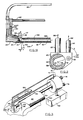
- FIG. 1 A plasma spray gun 10 incorporating the present invention is illustrated in FIG. 1.
- the plasma generating end 12 of the gun is of the conventional type.
- a main gun body 14 has affixed thereto and progressively rearwardly thereof a main insulator 16 and a cathode block 18 .
- the main insulator has an outer portion 20 insulating the gun body from the cathode block and a generally cylindrical projection 22 extending forwardly into gun body 14 .
- a cathode assembly 24 is retained coaxially in main insulator 16 and electrode block 18 .
- the assembly includes an electrically conducting cylindrical cathode holder 26 .
- the assembly is fitted in a cylindrical insulator ring 28 which in turn is held in an axial bore 30 in forward projection 22 of main insulator 16 .
- Cathode holder 26 is part of a rear retaining ring portion 32 .
- These concentric components are retained in body 14 with a ring 32 being threaded into electrode block 18 . Holes 34 in the ring facilitate wrench removal and replacement of the ring and assembly 24 .
- a plurality of O-rings 36 are appropriately arranged in O-ring grooves throughout the gun to retain coolant.
- a rod shaped cathode member 38 of assembly 24 has a forward tip 40 made of thoriated tungsten or other suitable arc cathode material.
- the tip is brazed to a cathode base 42 of copper or the like which has a rearwardly directed tubular portion 44 affixed with silver solder concentrically to cathode holder 26 .
- a plug member 46 is fitted into the rear of cathode holder 26 and has protruding forwardly therefrom a pipe 48 extending into the tubular portion 44 of cathode base 42 , defining an annular conduit 50 therebetween. Plug 46 is held with a pin 49 in rear retaining ring 32 .
- a nozzle anode assembly 52 fits into the forward end of main body 14 and includes a tubular anode 54 of copper or the like extending forwardly of cathode tip 40 .
- a flanged anode holder 56 retains the anode on body 14 by means of a nozzle flange 58 held to the body with screws 60 .
- a gas distribution ring 62 is located concentrically outside of cathode member 38 .
- One or more gas inlets 64 (preferably 6 inlets; two are shown) are directed radially inward, preferably with a tangential component to swirl the plasma gas.
- the inlets receive the gas flowing from an inner annular chamber 66 disposed outward of gas ring 62 , a plurality of gas ducts 68 , an outer annular chamber 70 and a gas duct 72 in body 14 connected to a source 74 of plasma forming gas.
- Duct 72 preferably leads rearward in generator 12 , but is shown transverse in FIG. 1 for clarity.
- a pair of electrical power cable connectors 76,78 from a conventional electrical arc power source 79 are threaded respectively into cathode block 18 and main body 14 .
- These components and others not otherwise designated herein are made of brass or the like for ease of fabrication and conduction of current.
- Arc current thus flows from body 14 through anode holder 56 to anode 54 where an arc is formed to cathode member 38 thus generating a plasma stream in the plasma-forming gas.
- the current flow continues from the tip through the cathode base 42 , retaining ring 32 and cathode block 18 .
- Fluid coolant typically water
- a pressurized source 80 through power cable 78 to a main channel 81 in main body 14 .
- a first branch 82 from the main channel connects to a first series of concentrically arranged annular and radial channels 84 between and through main insulator 16 , insulator ring 28 and cathode holder 26 to annular duct 50 for cooling cathode member 38 .
- the cathode coolant then exits through pipe 48 and a second series of concentrically arranged annular and radial channels 86 to a fluid disposal channel 88 in main body 14 and out of the other power cable 76 to a drain 90 or, alternatively, to a heat exchanger for recirculation.
- a second branch channel 92 from main channel 81 leads coolant to an annulus 94 between anode holder 56 and body 14 and thence through four radial channels 96 (one shown) to an annular coolant duct 98 about anode 54 .
- the anode coolant then exits through a second channel 100 feeding to an annular chamber 102 formed between anode holder 56 and main body 14 to disposal channel 88 .
- an elongated tubular extension 104 extends forwardly from anode 54 .
- the extension is formed by a tubular wall structure, comprising an outer wall 106 and an inner wall 108 , forming an axial plasma duct 110 extending forwardly from anode 54 .
- the outer wall is silver soldered to nozzle flange 58 .
- inner wall 108 is simply an extension of the tubular anode, i.e. has an inner surface 112 that is a continuation of a similar inner surface of the anode, so that the arc may seek a natural terminus on the smooth inner surface as far forward as possible, thereby maximizing power transfer to the plasma stream from the arc.
- the forward end of plasma duct 110 is terminated by an end wall 114 distal of anode 54 .
- the tubular extension has a transverse plasma duct 116 therein formed in part by end wall 114 for diverting and exiting the plasma stream transversely from tubular extension 104 .
- the transverse duct has a sufficient lateral component for plasma stream 117 to exit transversely, the duct (and issuing plasma) should retain a forward component to minimize hot gas erosion of the end wall and minimize heat loss to the end wall, and for other reasons explained below.
- Channeling 118 for fluid coolant, between outer and inner walls 106,108 extends substantially the length of axial plasma duct 110 , sufficient for flowing coolant such as water to cool the length of the plasma duct.
- the channeling may be in the form of a plurality of parallel bores in an otherwise solid tubular wall structure, but preferably is an annular space as described herein.
- An end fitting 120 is provided at the forward end of extension 104 , forwardly of transverse duct 116 .
- An external pipe 122 is soldered to the end fitting and, in the present embodiment, leads transversely away from extension 104 .
- Pipe 122 is in fluid flow communication with channeling 118 by way of a coolant region 124 proximate end wall 114 , connecting to the channeling.
- External pipe 122 continues as a rigid pipe or a flexible hose 126 to a body fitting 128 communicating with a third branch channel 130 from main channel 81 source of coolant in main body 14 of gun 10 .
- the coolant thereby is caused to flow through the external tube 122 to region 124 proximate transverse duct 116 , rearwardly along channeling 118 , and through a third radial channel 132 to chamber 102 and disposal channel 88 .
- a powder injector 134 comprising a short pipe 136 is disposed forwardly adjacent transverse duct 116 and aimed to inject spray powder 138 rearwardly into exiting plasma stream 117 .
- a second external pipe 140 is connected to powder injector 134 in powder flow communication therewith.
- the second pipe leads via tubing 142 from a powder fitting 143 and a powder duct 144 in main gun body 14 .
- Duct 144 preferably leads rearward in generator 12 , but is shown transverse in FIG. 1 for clarity.
- the powder duct is receptive of spray powder, typically in a carrier gas, from a conventional powder source 146 such as of the type described in U.S. Patent No. 4,561,808 (Spaulding et al), e.g. a Metco Type 4MP feeder sold by The Perkin- Elmer Corporation, Norwalk Connecticut.
- the powder is generally melted or at least heat softened and directed to a surface to be coated.
- the rearwardly injected powder in its carrier gas enters the plasma stream near the exit of duct 116 , with plasma stream 117 having a small forward component angle A such as 10 o to 30 o , e.g. 20 o to a normal to the axis of the longitudinal duct.
- the injected powder-carrier stream 138 further deflects the plasma spray stream towards perpendicular. Suggested dimensions are 4mm diameter for transverse duct 116 , and 1.6mm internal diameter for powder pipe 136 .
- FIG. 1 shows the external pipes 122 and 140 lying in the same plane as axis 148 of transverse duct 116 .
- the transverse duct should be rotated on axis 148 with respect to the pipes.
- first external pipe 122 for coolant being connected via fitting 120 to tubular extension 104 from a first direction 150
- second external pipe 140 for powder being connected via fitting 120 to powder injector 136 from a second direction 152 preferably the same as (parallel to) the first direction
- transverse duct 116 should exit in a third direction 154 arcuately spaced at an angle B from the first and second directions about the main axis of the extension.
- the arcuate spacing should be established as required for the recessed region to be sprayed, and is, for example, 60 o in FIG. 2.
- the plasma gun of the present invention is particularly suitable for spraying inside surfaces of a recessed region in the form of a dovetail slot 158 of a workpiece 160 accessible from at least one end of the slot as illustrated in FIG. 3.
- Examples of the kind of dovetail slots that may be coated are roots and connecting hub regions of turbine blades for gas turbine engines.
- the gun should be mounted on a machine 162 which oscillates the gun back and forth in the slot and rotates the gun by an indexed amount each cycle (or half cycle). Alternatively the part being coated may be moved.
- the total rotation for the embodiment shown is limited by the size of the slot opening 164 and the external coolant and powder pipes 122,140 extending therethrough, but should be sufficient for coating the otherwise inaccessible surfaces.
- a similar gun of opposite polarity of the transverse duct with respect to the pipes may be used for the other side of the slot, or the same gun may be inserted into the other end of the slot.
- the bottom surface of the slot may be coated conventionally.
- a further embodiment allows coating ordinary holes, as distinct from slots, where a hole is open at both ends.
- the pipes or end fitting should be readily removable from the tubular extension.
- the gun with pipes disconnected, may be inserted through the hole and the pipes reconnected.
- the pipes are led back to the gun main body via whatever routing is necessary for the external geometry of the item being coated.
- the extension should be long enough to spray the recess length intended, but not so long as to allow excessive cooling of the plasma stream. Higher melting powders may require a shorter extension with less heat loss. Some extra length may be obtained with an alternative construction (not shown) wherein the forward face of the main body is moved rearward so as to extend laterally from proximate the cathode tip, and the rear of the extension is configured as the anode.
- a gun according to the present invention with a plasma duct length of 12.5cm from the cathode tip to the end wall (on axis), a plasma duct diameter of 4.0mm, an extension outside diameter of 7.9mm is suitable for spraying copper-nickel-indium powder having constituent weight ratios of 59:36:5 and a size of - 44 +16 microns. Coatings up to 0.25mm thick may be sprayed in dovetail slots for vanes of a gas turbine engine, the slots being 3.8cm long with a cross sectional diameter of 1.7cm and a slot opening of 1.2cm.
- Arcuate separation angle B of the transverse duct from the external pipes (FIG. 2) was 60 o .
- Plasma gas was a mixture of argon at 708 l/hr (25 scfh) and nitrogen at 708 l/hr (25 scfh); the gun was started on neat argon at 1416 l/hr (50 scfh). Arc current was 400 amperes at 70 volts. Power loss to the cooling water was 72% of the power input, so output power was 7.8 KW. Spray distance was 0.64cm, and powder feed rate in argon carrier gas was 1.5 kg/hr. Suitable coatings for the purpose of dovetail slots were obtained, and the gun can be operated at least 10 hours without excessive erosion of the end wall.
- the present invention allows spraying in such slotted regions, since the combination of removing the plasma generating cathode-anode assemblies from the plasma duct, and external pipes for the coolant and the powder, allow for a much smaller extension diameter for the plasma stream than heretofore achieved. Improved flexibility is also achieved for spraying into larger areas. Furthermore the coolant input from the end of the extension provides for optimum cooling of the end wall where the impinging plasma stream could otherwise cause excessive erosion. Further optimization is provided for powder injection into the plasma, being at an oblique angle from a direction with respect to the stream such as to have an injection component against the stream, to effect good entrainment and push the plasma spray stream closer to a perpendicular spray angle.
Landscapes
- Physics & Mathematics (AREA)
- Engineering & Computer Science (AREA)
- Plasma & Fusion (AREA)
- Electromagnetism (AREA)
- Spectroscopy & Molecular Physics (AREA)
- Plasma Technology (AREA)
- Nozzles (AREA)
- Coating By Spraying Or Casting (AREA)
Applications Claiming Priority (2)
| Application Number | Priority Date | Filing Date | Title |
|---|---|---|---|
| US07/254,001 US4853515A (en) | 1988-09-30 | 1988-09-30 | Plasma gun extension for coating slots |
| US254001 | 1988-09-30 |
Publications (2)
| Publication Number | Publication Date |
|---|---|
| EP0362693A1 true EP0362693A1 (de) | 1990-04-11 |
| EP0362693B1 EP0362693B1 (de) | 1993-12-15 |
Family
ID=22962544
Family Applications (1)
| Application Number | Title | Priority Date | Filing Date |
|---|---|---|---|
| EP89117947A Expired - Lifetime EP0362693B1 (de) | 1988-09-30 | 1989-09-28 | Plasmaspritzbrennerverlängerung zum Anbringen von Schichten in Nuten |
Country Status (7)
| Country | Link |
|---|---|
| US (1) | US4853515A (de) |
| EP (1) | EP0362693B1 (de) |
| JP (1) | JP2815418B2 (de) |
| CN (1) | CN1041506A (de) |
| BR (1) | BR8904877A (de) |
| CA (1) | CA1317102C (de) |
| DE (1) | DE68911457T2 (de) |
Cited By (1)
| Publication number | Priority date | Publication date | Assignee | Title |
|---|---|---|---|---|
| CN104244556A (zh) * | 2014-10-15 | 2014-12-24 | 周开根 | 一种组合式喷管阳极 |
Families Citing this family (34)
| Publication number | Priority date | Publication date | Assignee | Title |
|---|---|---|---|---|
| US5262616A (en) * | 1989-11-08 | 1993-11-16 | Societe Nationale Industrielle Et Aerospatiale | Plasma torch for noncooled injection of plasmagene gas |
| US5004888A (en) * | 1989-12-21 | 1991-04-02 | Westinghouse Electric Corp. | Plasma torch with extended life electrodes |
| US6359872B1 (en) * | 1997-10-28 | 2002-03-19 | Intermec Ip Corp. | Wireless personal local area network |
| US5233153A (en) * | 1992-01-10 | 1993-08-03 | Edo Corporation | Method of plasma spraying of polymer compositions onto a target surface |
| US5624586A (en) * | 1995-01-04 | 1997-04-29 | Hypertherm, Inc. | Alignment device and method for a plasma arc torch system |
| US5793013A (en) * | 1995-06-07 | 1998-08-11 | Physical Sciences, Inc. | Microwave-driven plasma spraying apparatus and method for spraying |
| JP2004527878A (ja) | 2001-03-09 | 2004-09-09 | ハイパーサーム インコーポレイテッド | プラズマアークトーチ用複合電極 |
| US7324011B2 (en) * | 2004-04-14 | 2008-01-29 | Battelle Energy Alliance, Llc | Method and system for pipeline communication |
| US7334485B2 (en) * | 2002-02-11 | 2008-02-26 | Battelle Energy Alliance, Llc | System, method and computer-readable medium for locating physical phenomena |
| US6889557B2 (en) * | 2002-02-11 | 2005-05-10 | Bechtel Bwxt Idaho, Llc | Network and topology for identifying, locating and quantifying physical phenomena, systems and methods for employing same |
| US7276264B1 (en) * | 2002-02-11 | 2007-10-02 | Battelle Energy Alliance, Llc | Methods for coating conduit interior surfaces utilizing a thermal spray gun with extension arm |
| US6916502B2 (en) * | 2002-02-11 | 2005-07-12 | Battelle Energy Alliance, Llc | Systems and methods for coating conduit interior surfaces utilizing a thermal spray gun with extension arm |
| CN1298881C (zh) * | 2004-10-28 | 2007-02-07 | 河北工业大学 | 反应等离子喷涂反应室装置 |
| SE529053C2 (sv) | 2005-07-08 | 2007-04-17 | Plasma Surgical Invest Ltd | Plasmaalstrande anordning, plasmakirurgisk anordning och användning av en plasmakirurgisk anordning |
| SE529056C2 (sv) | 2005-07-08 | 2007-04-17 | Plasma Surgical Invest Ltd | Plasmaalstrande anordning, plasmakirurgisk anordning och användning av en plasmakirurgisk anordning |
| SE529058C2 (sv) | 2005-07-08 | 2007-04-17 | Plasma Surgical Invest Ltd | Plasmaalstrande anordning, plasmakirurgisk anordning, användning av en plasmakirurgisk anordning och förfarande för att bilda ett plasma |
| FI119923B (fi) * | 2005-09-08 | 2009-05-15 | Kemppi Oy | Menetelmä ja laitteisto lyhytkaarihitsausta varten |
| USD545851S1 (en) | 2006-03-30 | 2007-07-03 | Dave Hawley | Plasma gun nozzle holder |
| DE102006061435A1 (de) * | 2006-12-23 | 2008-06-26 | Leoni Ag | Verfahren und Vorrichtung zum Aufspritzen insbesondere einer Leiterbahn, elektrisches Bauteil mit einer Leiterbahn sowie Dosiervorrichtung |
| US7928338B2 (en) | 2007-02-02 | 2011-04-19 | Plasma Surgical Investments Ltd. | Plasma spraying device and method |
| US20080190253A1 (en) * | 2007-02-09 | 2008-08-14 | United Technologies Corporation | Ergonomic plasma spray gun tool |
| CN101296552B (zh) * | 2007-04-25 | 2011-04-20 | 烟台龙源电力技术股份有限公司 | 等离子发生器的输送弧装置 |
| US7589473B2 (en) * | 2007-08-06 | 2009-09-15 | Plasma Surgical Investments, Ltd. | Pulsed plasma device and method for generating pulsed plasma |
| US8735766B2 (en) | 2007-08-06 | 2014-05-27 | Plasma Surgical Investments Limited | Cathode assembly and method for pulsed plasma generation |
| SE532457C2 (sv) * | 2008-07-03 | 2010-01-26 | Esab Ab | Pulverhanteringsanordning för svetsning under pulver |
| US8613742B2 (en) | 2010-01-29 | 2013-12-24 | Plasma Surgical Investments Limited | Methods of sealing vessels using plasma |
| US9089319B2 (en) | 2010-07-22 | 2015-07-28 | Plasma Surgical Investments Limited | Volumetrically oscillating plasma flows |
| US9272360B2 (en) * | 2013-03-12 | 2016-03-01 | General Electric Company | Universal plasma extension gun |
| USD824966S1 (en) | 2016-10-14 | 2018-08-07 | Oerlikon Metco (Us) Inc. | Powder injector |
| US10435779B2 (en) * | 2017-03-14 | 2019-10-08 | Ford Motor Company | Precision air flow routing devices and method for thermal spray coating applications |
| USD823906S1 (en) | 2017-04-13 | 2018-07-24 | Oerlikon Metco (Us) Inc. | Powder injector |
| US10612122B2 (en) | 2017-08-25 | 2020-04-07 | Vladimir E. Belashchenko | Plasma device and method for delivery of plasma and spray material at extended locations from an anode arc root attachment |
| EP4205515A2 (de) | 2020-08-28 | 2023-07-05 | Plasma Surgical Investments Limited | Systeme, verfahren und vorrichtungen zur erzeugung eines überwiegend radial expandierten plasmaflusses |
| CN216698399U (zh) * | 2021-12-23 | 2022-06-07 | 宁德时代新能源科技股份有限公司 | 等离子喷射装置、喷涂设备及太阳能电池制造设备 |
Citations (3)
| Publication number | Priority date | Publication date | Assignee | Title |
|---|---|---|---|---|
| GB1240124A (en) * | 1967-12-01 | 1971-07-21 | Ass Eng Ltd | Improvements in plasma guns |
| EP0171793A2 (de) * | 1984-08-17 | 1986-02-19 | Plasmainvent AG | Plasmaspritzbrenner mit gekühlter Elektrode und Brennerdüse |
| EP0271032A2 (de) * | 1986-12-11 | 1988-06-15 | Castolin S.A. | Verfahren zur Aufbringung einer Innenbeschichtung in Rohre od. dgl. Hohlräume engen Querschnittes sowie Plasmaspritzbrenner dafür |
Family Cites Families (9)
| Publication number | Priority date | Publication date | Assignee | Title |
|---|---|---|---|---|
| US2922869A (en) * | 1958-07-07 | 1960-01-26 | Plasmadyne Corp | Plasma stream apparatus and methods |
| US4146654A (en) * | 1967-10-11 | 1979-03-27 | Centre National De La Recherche Scientifique | Process for making linings for friction operated apparatus |
| US3740522A (en) * | 1971-04-12 | 1973-06-19 | Geotel Inc | Plasma torch, and electrode means therefor |
| US4423304A (en) * | 1981-02-20 | 1983-12-27 | Bass Harold E | Plasma welding torch |
| US4540121A (en) * | 1981-07-28 | 1985-09-10 | Browning James A | Highly concentrated supersonic material flame spray method and apparatus |
| BE898951A (fr) * | 1984-02-17 | 1984-08-17 | Centre Rech Metallurgique | Torche a plasma a arc electrique. |
| US4561808A (en) * | 1984-06-04 | 1985-12-31 | Metco Inc. | Powder feed pickup device for thermal spray guns |
| US4696855A (en) * | 1986-04-28 | 1987-09-29 | United Technologies Corporation | Multiple port plasma spray apparatus and method for providing sprayed abradable coatings |
| US4681772A (en) * | 1986-05-05 | 1987-07-21 | General Electric Company | Method of producing extended area high quality plasma spray deposits |
-
1988
- 1988-09-30 US US07/254,001 patent/US4853515A/en not_active Expired - Fee Related
-
1989
- 1989-07-26 CA CA000606749A patent/CA1317102C/en not_active Expired - Fee Related
- 1989-08-16 CN CN89106602.0A patent/CN1041506A/zh active Pending
- 1989-09-26 BR BR898904877A patent/BR8904877A/pt unknown
- 1989-09-28 EP EP89117947A patent/EP0362693B1/de not_active Expired - Lifetime
- 1989-09-28 DE DE89117947T patent/DE68911457T2/de not_active Expired - Fee Related
- 1989-09-29 JP JP1252494A patent/JP2815418B2/ja not_active Expired - Lifetime
Patent Citations (3)
| Publication number | Priority date | Publication date | Assignee | Title |
|---|---|---|---|---|
| GB1240124A (en) * | 1967-12-01 | 1971-07-21 | Ass Eng Ltd | Improvements in plasma guns |
| EP0171793A2 (de) * | 1984-08-17 | 1986-02-19 | Plasmainvent AG | Plasmaspritzbrenner mit gekühlter Elektrode und Brennerdüse |
| EP0271032A2 (de) * | 1986-12-11 | 1988-06-15 | Castolin S.A. | Verfahren zur Aufbringung einer Innenbeschichtung in Rohre od. dgl. Hohlräume engen Querschnittes sowie Plasmaspritzbrenner dafür |
Cited By (1)
| Publication number | Priority date | Publication date | Assignee | Title |
|---|---|---|---|---|
| CN104244556A (zh) * | 2014-10-15 | 2014-12-24 | 周开根 | 一种组合式喷管阳极 |
Also Published As
| Publication number | Publication date |
|---|---|
| CA1317102C (en) | 1993-05-04 |
| JPH02142098A (ja) | 1990-05-31 |
| DE68911457D1 (de) | 1994-01-27 |
| BR8904877A (pt) | 1990-05-08 |
| EP0362693B1 (de) | 1993-12-15 |
| DE68911457T2 (de) | 1994-04-07 |
| CN1041506A (zh) | 1990-04-18 |
| JP2815418B2 (ja) | 1998-10-27 |
| US4853515A (en) | 1989-08-01 |
Similar Documents
| Publication | Publication Date | Title |
|---|---|---|
| EP0362693B1 (de) | Plasmaspritzbrennerverlängerung zum Anbringen von Schichten in Nuten | |
| EP0457067B1 (de) | Plasmaspritzvorrichtung mit äusserlicher Pulverzuführung | |
| US5362939A (en) | Convertible plasma arc torch and method of use | |
| EP0775436B1 (de) | Plasmabrenner mit axialer pulverinjektion | |
| CN112024885B (zh) | 一种等离子弧喷头及具有其的等离子发生装置和三维打印设备 | |
| US4127760A (en) | Electrical plasma jet torch and electrode therefor | |
| US3914573A (en) | Coating heat softened particles by projection in a plasma stream of Mach 1 to Mach 3 velocity | |
| EP0640022B1 (de) | Plasma aus hoher temperatur verbrauchende spritzpistole | |
| US3823302A (en) | Apparatus and method for plasma spraying | |
| EP0173902B1 (de) | Düse für eine Plasmaspritzpistole | |
| US5109150A (en) | Open-arc plasma wire spray method and apparatus | |
| JPH0357833B2 (de) | ||
| CA2265240A1 (en) | Arc thermal spray gun extension and gas jet member therefor | |
| CA1314944C (en) | Arc spray gun for coating confined areas | |
| US4587397A (en) | Plasma arc torch | |
| US10612122B2 (en) | Plasma device and method for delivery of plasma and spray material at extended locations from an anode arc root attachment | |
| JPS61216760A (ja) | プラズマ・アーク・トーチ | |
| WO1989000476A1 (en) | Burner for plasma cutting and welding | |
| US9227214B2 (en) | Adjustable gas distribution assembly and related adjustable plasma spray device | |
| RU2060130C1 (ru) | Плазмотрон | |
| KR20250053401A (ko) | 플라즈마 용사 건 |
Legal Events
| Date | Code | Title | Description |
|---|---|---|---|
| PUAI | Public reference made under article 153(3) epc to a published international application that has entered the european phase |
Free format text: ORIGINAL CODE: 0009012 |
|
| AK | Designated contracting states |
Kind code of ref document: A1 Designated state(s): CH DE FR GB IT LI |
|
| 17P | Request for examination filed |
Effective date: 19901011 |
|
| 17Q | First examination report despatched |
Effective date: 19930201 |
|
| GRAA | (expected) grant |
Free format text: ORIGINAL CODE: 0009210 |
|
| AK | Designated contracting states |
Kind code of ref document: B1 Designated state(s): CH DE FR GB IT LI |
|
| REF | Corresponds to: |
Ref document number: 68911457 Country of ref document: DE Date of ref document: 19940127 |
|
| ITF | It: translation for a ep patent filed | ||
| ET | Fr: translation filed | ||
| PLBE | No opposition filed within time limit |
Free format text: ORIGINAL CODE: 0009261 |
|
| STAA | Information on the status of an ep patent application or granted ep patent |
Free format text: STATUS: NO OPPOSITION FILED WITHIN TIME LIMIT |
|
| 26N | No opposition filed | ||
| REG | Reference to a national code |
Ref country code: CH Ref legal event code: PUE Owner name: THE PERKIN-ELMER CORPORATION TRANSFER- SULZER METC |
|
| PGFP | Annual fee paid to national office [announced via postgrant information from national office to epo] |
Ref country code: GB Payment date: 19990902 Year of fee payment: 11 Ref country code: FR Payment date: 19990902 Year of fee payment: 11 Ref country code: DE Payment date: 19990902 Year of fee payment: 11 |
|
| PGFP | Annual fee paid to national office [announced via postgrant information from national office to epo] |
Ref country code: CH Payment date: 19990903 Year of fee payment: 11 |
|
| REG | Reference to a national code |
Ref country code: GB Ref legal event code: 732E |
|
| REG | Reference to a national code |
Ref country code: FR Ref legal event code: TP |
|
| PG25 | Lapsed in a contracting state [announced via postgrant information from national office to epo] |
Ref country code: GB Free format text: LAPSE BECAUSE OF NON-PAYMENT OF DUE FEES Effective date: 20000928 |
|
| PG25 | Lapsed in a contracting state [announced via postgrant information from national office to epo] |
Ref country code: LI Free format text: LAPSE BECAUSE OF NON-PAYMENT OF DUE FEES Effective date: 20000930 Ref country code: CH Free format text: LAPSE BECAUSE OF NON-PAYMENT OF DUE FEES Effective date: 20000930 |
|
| REG | Reference to a national code |
Ref country code: CH Ref legal event code: PL |
|
| GBPC | Gb: european patent ceased through non-payment of renewal fee |
Effective date: 20000928 |
|
| PG25 | Lapsed in a contracting state [announced via postgrant information from national office to epo] |
Ref country code: FR Free format text: LAPSE BECAUSE OF NON-PAYMENT OF DUE FEES Effective date: 20010531 |
|
| PG25 | Lapsed in a contracting state [announced via postgrant information from national office to epo] |
Ref country code: DE Free format text: LAPSE BECAUSE OF NON-PAYMENT OF DUE FEES Effective date: 20010601 |
|
| REG | Reference to a national code |
Ref country code: FR Ref legal event code: ST |
|
| PG25 | Lapsed in a contracting state [announced via postgrant information from national office to epo] |
Ref country code: IT Free format text: LAPSE BECAUSE OF NON-PAYMENT OF DUE FEES;WARNING: LAPSES OF ITALIAN PATENTS WITH EFFECTIVE DATE BEFORE 2007 MAY HAVE OCCURRED AT ANY TIME BEFORE 2007. THE CORRECT EFFECTIVE DATE MAY BE DIFFERENT FROM THE ONE RECORDED. Effective date: 20050928 |