EP0362745A1 - Multimètre électronique - Google Patents
Multimètre électronique Download PDFInfo
- Publication number
- EP0362745A1 EP0362745A1 EP89118177A EP89118177A EP0362745A1 EP 0362745 A1 EP0362745 A1 EP 0362745A1 EP 89118177 A EP89118177 A EP 89118177A EP 89118177 A EP89118177 A EP 89118177A EP 0362745 A1 EP0362745 A1 EP 0362745A1
- Authority
- EP
- European Patent Office
- Prior art keywords
- measuring
- measuring device
- resistor
- series
- protective
- Prior art date
- Legal status (The legal status is an assumption and is not a legal conclusion. Google has not performed a legal analysis and makes no representation as to the accuracy of the status listed.)
- Granted
Links
- 230000001681 protective effect Effects 0.000 claims abstract description 35
- 238000005259 measurement Methods 0.000 claims description 6
- 230000017525 heat dissipation Effects 0.000 claims description 2
- 239000000523 sample Substances 0.000 claims 1
- 231100001261 hazardous Toxicity 0.000 abstract 1
- 238000011144 upstream manufacturing Methods 0.000 description 4
- 230000006378 damage Effects 0.000 description 2
- 230000001419 dependent effect Effects 0.000 description 2
- 238000011161 development Methods 0.000 description 2
- 230000018109 developmental process Effects 0.000 description 2
- 238000000034 method Methods 0.000 description 2
- 238000010276 construction Methods 0.000 description 1
- 238000010586 diagram Methods 0.000 description 1
- 238000005516 engineering process Methods 0.000 description 1
- 230000001771 impaired effect Effects 0.000 description 1
- 230000001939 inductive effect Effects 0.000 description 1
- 239000000463 material Substances 0.000 description 1
- 239000002184 metal Substances 0.000 description 1
- 238000007493 shaping process Methods 0.000 description 1
- 230000011664 signaling Effects 0.000 description 1
- 230000001960 triggered effect Effects 0.000 description 1
Images

Classifications
-
- G—PHYSICS
- G01—MEASURING; TESTING
- G01R—MEASURING ELECTRIC VARIABLES; MEASURING MAGNETIC VARIABLES
- G01R1/00—Details of instruments or arrangements of the types included in groups G01R5/00 - G01R13/00 and G01R31/00
- G01R1/36—Overload-protection arrangements or circuits for electric measuring instruments
Definitions
- the invention relates to a measuring device mentioned in the preamble of claim 1.
- Electronic multi-range measuring devices in particular multiple measuring devices with high input resistance, are preferably used in the laboratory and electronics area. Voltages higher than the mains voltage of 220 V do not usually occur here, so that it is sufficient to protect these devices against overvoltages up to 1 kV by a surge arrester, which can be designed as a spark gap or voltage-dependent resistor. Even if the protective device provided with a surge arrester and a fuse or a PTC thermistor should fail, the fuses of 16 A or 20 A provided in the network offer sufficient protection, at least for the operator of the measuring device, so that only material damage can occur.
- the object of the invention is to build conventional multiple measuring devices with voltage, current and possibly also resistance ranges so that they can also be used in low-voltage systems without an unreasonably high safety risk, where surge peaks of several kilovolts can occur. Thereby, the dangers arising from overvoltages as well as from operating errors of the multi-range measuring device should be eliminated.
- a major advantage of the invention is that the structure of the multi-range measuring devices can be left unchanged, and its area of application can also be extended to low-voltage systems simply by replacing a measuring line in which there is now a measuring adapter. Since it is possible to limit the protective resistor to approx. 15 kOhm, this, in conjunction with an input resistance of the multimeter of approx. 10 MOhm, leads to an additional measurement error of only 0.15%. With a basic error of the multimeter of approx. 1%, such deviations are tolerable.
- measuring heads acting as measuring adapters, but their function is aimed at solving measuring problems.
- a measuring adapter which deteriorates the measuring result from a measuring point of view and is only intended to protect the measuring device and the operator, requires completely new considerations.
- measuring devices which are built directly into the measuring tips are unable to give any indication of the solution to the problem according to the invention, since they only appear externally as measuring adapters, but their safety can be impaired in the same way by interference voltages and incorrect operation.
- a limiting network can be used as the protective resistor, which consists of several individual resistors connected in series and thereby enables good heat dissipation and can withstand relatively high voltages.
- the effectiveness of the protective resistor can be significantly improved in that at least one of the series-connected resistors of the limiting network is designed as a PTC resistor, that is to say as a resistor with a positive temperature coefficient.
- the effectiveness of the protective resistor essentially depends on the dimensioning of the limiting network.
- the total resistance of the individual resistors in series is important and the ratio of the PTC resistance to the remaining residual resistance must also be observed.
- the dimensioning must be such that the resistance of the network in the event of overvoltages limits the input current to a value which is harmless for the input circuit of the multi-range measuring device and extinguishes an arc which has arisen in the input circuit of the multi-range measuring device.
- the overcurrent which jeopardizes the individual resistances must be reduced to a permissible value. This function is performed by a PTC resistor connected in series with the individual resistors, which, when activated, limits the input current to a value that is safe for the input circuit and the individual resistors.
- the measuring object could be simulated to be without voltage despite the measuring voltage being present due to the missing display of the measuring device. Incorrect operation of the measuring device can also lead to such deception. So that the operator is not misled into a fault in such a case, it is advantageous to bridge the protective resistor with a redundant resistor, the resistance of which is at least one order of magnitude higher than the protective resistor. As a result, a measuring voltage is displayed on the measuring device even if the protective resistor is interrupted, but with an increased measuring error.
- the measuring adapter is structurally preferable to provide the measuring adapter with a housing in which the protective resistor and possibly the other components are accommodated and can preferably be mounted on a circuit board.
- a contact element preferably a measuring tip, can be attached to its free end, which is not connected to the measuring line, and it can be ensured by suitable shaping that the housing can be comfortably held in one hand when contacting the measuring object.
- the multi-range measuring device consists of a measuring part MT, an upstream input circuit ES and a measuring adapter A, which is connected to at least one of the two inputs E1, E2 of the input circuit ES.
- the input circuit ES serves for protection of the measuring part MT against overvoltages and for this purpose is equipped with a spark gap F which short-circuits the input of the measuring part MT via a resistor RS.
- a fuse S is connected upstream, which interrupts the measuring circuit at a corresponding level and duration of the current.
- the structure of input circuits of this type can vary and, for example, can also be equipped with a voltage-dependent resistor (varistor) instead of the spark gap. However, they are all based on the principle that overvoltages that exceed a certain limit value are virtually short-circuited.
- an adapter A is connected upstream thereof, the basic configuration of which contains a protective resistor R1 to R9.
- This protective resistor lies in series with a measuring line which extends between the input E1 of the input circuit ES and a measuring contact K1 contacting the test object.
- the effectiveness of the protective circuit is significantly increased by a PTC thermistor R1, which is connected in series with the other resistors R2-R9, which are preferably designed as wire or metal film resistors. It must be taken into account here that the protective resistance R1 to R9 should be as low as possible from the point of view of measurement accuracy. Its maximum value is determined by the input resistance of the input circuit ES, which in turn depends on the input resistance of the measuring part MT. However, in order to be able to fulfill its task of sufficient current limitation, the protective resistor must not fall below a minimum value.
- the protective circuit is to be dimensioned for overvoltages up to 8 kV, it is advantageous to give the PTC resistor R1 a resistance of 7.5 kOhm and to provide the remaining individual resistors R2 to R9 with a value of 500 to 1000 ohms.
- a redundant resistor R10 to R16 can be connected in parallel to the protective resistor R1 to R9.
- the redundancy resistor R10 to R16 is designed to have a significantly higher resistance than the protective resistor R1 to R9 and would lead to a larger measurement error, which is insignificant because its task the only thing is to signal an applied measuring voltage. If necessary, you can place a button in series with the redundancy resistor R10 to R16, so that it is only connected in parallel to the protective resistor R1 to R9 in the test case.
- a voltage signaling can also be carried out with the aid of a glow lamp G, which by means of its series resistor R17 to R23 bridges the protective resistor R1 to R9 and the input E1, E2 of the input circuit ES connected in series therewith.
- a glow lamp G which by means of its series resistor R17 to R23 bridges the protective resistor R1 to R9 and the input E1, E2 of the input circuit ES connected in series therewith.
- Such a circuit has the advantage that it also signals applied measuring voltages if the fuse of the input circuit ES should have blown or an error occurs in the measuring part MT of the multi-range measuring device.
- a pluggable adapter as it should preferably be used, it is disadvantageous that it would have to be designed with two poles in order to also establish a connection to the second input E2 of the input circuit.
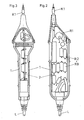
- FIGS. 2 and 3 show the mechanical structure of the measuring adapter A.
- a measuring adapter housing 1 is attached to the end of a measuring line L and is provided at its free end with a contacting part K1 designed as a measuring tip.
- a circuit board on which the series resistors R1 to R9 of the protective resistor are arranged.
- the PTC resistor R1 which acts as a PTC thermistor and whose temperature can rise to particularly high values in the event of a fault, is located in the vicinity of the contact part K1, which can thus dissipate part of the heat.
Landscapes
- Physics & Mathematics (AREA)
- General Physics & Mathematics (AREA)
- Emergency Protection Circuit Devices (AREA)
- Measurement Of Current Or Voltage (AREA)
- Radar Systems Or Details Thereof (AREA)
Applications Claiming Priority (2)
| Application Number | Priority Date | Filing Date | Title |
|---|---|---|---|
| DE3834183A DE3834183A1 (de) | 1988-10-07 | 1988-10-07 | Elektronisches mehrbereichsmessgeraet |
| DE3834183 | 1988-10-07 |
Publications (2)
| Publication Number | Publication Date |
|---|---|
| EP0362745A1 true EP0362745A1 (fr) | 1990-04-11 |
| EP0362745B1 EP0362745B1 (fr) | 1994-06-01 |
Family
ID=6364622
Family Applications (1)
| Application Number | Title | Priority Date | Filing Date |
|---|---|---|---|
| EP89118177A Expired - Lifetime EP0362745B1 (fr) | 1988-10-07 | 1989-09-30 | Multimètre électronique |
Country Status (3)
| Country | Link |
|---|---|
| EP (1) | EP0362745B1 (fr) |
| AT (1) | ATE106572T1 (fr) |
| DE (2) | DE3834183A1 (fr) |
Cited By (2)
| Publication number | Priority date | Publication date | Assignee | Title |
|---|---|---|---|---|
| EP0454013A3 (en) * | 1990-04-27 | 1992-06-03 | Abb Patent Gmbh | Measurement circuit for detecting a current |
| FR2707397A1 (fr) * | 1993-07-05 | 1995-01-13 | Itt Composants Instr | Dispositif électronique de protection, notamment pour la protection d'un ohmmètre. |
Families Citing this family (4)
| Publication number | Priority date | Publication date | Assignee | Title |
|---|---|---|---|---|
| DE9420949U1 (de) * | 1994-12-30 | 1995-05-18 | Conrad Electronic GmbH, 92242 Hirschau | Handmeßinstrument |
| DE19938117A1 (de) * | 1999-08-12 | 2001-03-15 | Reinisch Gmbh & Co Kg | Spannungsmeßvorrichtung |
| DE20301556U1 (de) * | 2003-02-01 | 2004-06-03 | Rosenhof, Viktor, Dr.-Ing. | Differentialer Hochspannungswandler zum Beispiel für ein PC-gesteuertes Messgerät |
| DE102004036540A1 (de) * | 2004-05-27 | 2005-12-22 | Gigatronik Gesellschaft für Automobilelektronikentwicklung mbH | Diagnosegerät |
Citations (4)
| Publication number | Priority date | Publication date | Assignee | Title |
|---|---|---|---|---|
| US2641630A (en) * | 1949-01-06 | 1953-06-09 | Prec Apparatus Co Inc | High-voltage multiplier probe |
| US3648166A (en) * | 1968-02-28 | 1972-03-07 | Westinghouse Electric Corp | Electrical device having current limiter and spark gap |
| US3710252A (en) * | 1969-12-17 | 1973-01-09 | Amp Inc | High voltage divider unit |
| GB2080956A (en) * | 1980-07-26 | 1982-02-10 | Marco Robin John Henry | A Meter Movement Protection Device |
Family Cites Families (9)
| Publication number | Priority date | Publication date | Assignee | Title |
|---|---|---|---|---|
| DE877169C (de) * | 1942-02-10 | 1953-05-21 | Siemens Ag | Amplitudenabhaengiges Netzwerk in Form einer Brueckenschaltung, insbesondere zum Schutz von Messinstrumenten gegen UEberstroeme |
| DE2717826C2 (de) * | 1977-04-21 | 1979-05-03 | Siemens Ag, 1000 Berlin Und 8000 Muenchen | Prüfeinrichtung zum Anzeigen einer elektrischen Spannung und/oder deren Polarität sowie des Stromdurchgangs durch einen elektrischen Leiter |
| DE2846675C3 (de) * | 1978-10-26 | 1981-08-13 | Siemens AG, 1000 Berlin und 8000 München | Prüfeinrichtung zum Anzeigen einer elektrischen Spannung und gegebenenfalls deren Polarität |
| DE2914761C2 (de) * | 1979-04-11 | 1980-11-06 | Siemens Ag, 1000 Berlin Und 8000 Muenchen | Gerät zum Messen von Gleich- oder Wechselspannungen sowie der Werte von elektrischen Widerständen |
| NL8001452A (nl) * | 1980-03-12 | 1981-10-01 | Philips Nv | Beveiligde stroommeetschakeling. |
| US4527118A (en) * | 1981-06-29 | 1985-07-02 | Siemens Aktiengesellschaft | Testing device for indicating an electric voltage and its polarity and for continuity testing |
| DE3213749A1 (de) * | 1982-04-14 | 1983-11-03 | Siemens AG, 1000 Berlin und 8000 München | Schaltungsanordnung zur erniedrigung des eingangswiderstandes einer zweipoligen hochohmigen pruefeinrichtung |
| DE3240831A1 (de) * | 1982-11-05 | 1984-05-10 | ANT Nachrichtentechnik GmbH, 7150 Backnang | Schaltungsanordnung zur ueberwachung einer isolierstrecke |
| JPH077016B2 (ja) * | 1986-03-06 | 1995-01-30 | 理研電子株式会社 | 電圧測定器用分圧器 |
-
1988
- 1988-10-07 DE DE3834183A patent/DE3834183A1/de not_active Withdrawn
-
1989
- 1989-09-30 DE DE58907762T patent/DE58907762D1/de not_active Expired - Fee Related
- 1989-09-30 AT AT89118177T patent/ATE106572T1/de not_active IP Right Cessation
- 1989-09-30 EP EP89118177A patent/EP0362745B1/fr not_active Expired - Lifetime
Patent Citations (4)
| Publication number | Priority date | Publication date | Assignee | Title |
|---|---|---|---|---|
| US2641630A (en) * | 1949-01-06 | 1953-06-09 | Prec Apparatus Co Inc | High-voltage multiplier probe |
| US3648166A (en) * | 1968-02-28 | 1972-03-07 | Westinghouse Electric Corp | Electrical device having current limiter and spark gap |
| US3710252A (en) * | 1969-12-17 | 1973-01-09 | Amp Inc | High voltage divider unit |
| GB2080956A (en) * | 1980-07-26 | 1982-02-10 | Marco Robin John Henry | A Meter Movement Protection Device |
Cited By (2)
| Publication number | Priority date | Publication date | Assignee | Title |
|---|---|---|---|---|
| EP0454013A3 (en) * | 1990-04-27 | 1992-06-03 | Abb Patent Gmbh | Measurement circuit for detecting a current |
| FR2707397A1 (fr) * | 1993-07-05 | 1995-01-13 | Itt Composants Instr | Dispositif électronique de protection, notamment pour la protection d'un ohmmètre. |
Also Published As
| Publication number | Publication date |
|---|---|
| DE3834183A1 (de) | 1990-04-12 |
| DE58907762D1 (de) | 1994-07-07 |
| EP0362745B1 (fr) | 1994-06-01 |
| ATE106572T1 (de) | 1994-06-15 |
Similar Documents
| Publication | Publication Date | Title |
|---|---|---|
| DE102013019391B4 (de) | Anordnung zum Überlastschutz von Überspannungsschutzgeräten | |
| DE60027354T2 (de) | Aktive Abschaltung bei Erdschlussfehler | |
| DE102011102941B4 (de) | Funkenstrecke mit mehreren in Reihe geschalteten, in einer Stapelanordnung befindlichen Einzelfunkenstrecken | |
| DE3228471C2 (de) | Überspannungsschutzgerät | |
| DE2439587B2 (de) | Vorrichtung für die Elektrochirurgie | |
| EP2377218A2 (fr) | Élément de protection contre les surtensions | |
| DE2902006A1 (de) | Ueberspannungsableiter | |
| WO2014026933A1 (fr) | Indicateur de défaillance de fusible | |
| AT401445B (de) | Überspannungsschutzanordnung | |
| EP0362745B1 (fr) | Multimètre électronique | |
| DE2917256C2 (fr) | ||
| EP0561149B1 (fr) | Arrangement pour l'alimentation en courant d'une électronique d'une réseau triphasé | |
| DE19914313B4 (de) | Überspannungsschutzsystem | |
| DE4220259C2 (de) | Schutzanordnung zum Schutz elektrischer Einrichtungen gegen Überspannungen auf dem Stromversorgungsnetz | |
| DE19751470A1 (de) | Überspannungsschutzvorrichtung | |
| EP0173016A2 (fr) | Installation électrique avec limiteurs de surtension | |
| EP0386288B1 (fr) | Dispositif de surveillance pour circuits électroniques ou pièces | |
| DE3539421C2 (fr) | ||
| DE102020001411A1 (de) | Überspannungsschutzschaltung mit Ausfallanzeige | |
| DE3522260A1 (de) | Elektrische installationsanlage zur speisung von verbrauchern aus einem netz | |
| DE102008005777A1 (de) | Gerät zur Zuverlässigkeitsprüfung eines nichtlinearen Überspannungsschutzes | |
| DE1959986A1 (de) | Vorrichtung zum Schutz von Leitungen,beispielsweise elektrischer Kabel gegen thermische UEberlastung | |
| DE19503237A1 (de) | Mehrpolige Anordnung von Überspannungsschutzelementen in elektrischen Mehrleitersystemen | |
| WO1998008281A1 (fr) | Dispositif d'affichage pour limiteur de tension | |
| DE1030432B (de) | Anordnung zur UEberwachung eines UEberspannungsableiters |
Legal Events
| Date | Code | Title | Description |
|---|---|---|---|
| PUAI | Public reference made under article 153(3) epc to a published international application that has entered the european phase |
Free format text: ORIGINAL CODE: 0009012 |
|
| AK | Designated contracting states |
Kind code of ref document: A1 Designated state(s): AT BE DE FR GB NL |
|
| 17P | Request for examination filed |
Effective date: 19901015 |
|
| RAP1 | Party data changed (applicant data changed or rights of an application transferred) |
Owner name: METRAWATT GMBH |
|
| 17Q | First examination report despatched |
Effective date: 19930510 |
|
| RAP1 | Party data changed (applicant data changed or rights of an application transferred) |
Owner name: GOSSEN- METRAWATT GMBH |
|
| GRAA | (expected) grant |
Free format text: ORIGINAL CODE: 0009210 |
|
| AK | Designated contracting states |
Kind code of ref document: B1 Designated state(s): AT BE DE FR GB NL |
|
| PG25 | Lapsed in a contracting state [announced via postgrant information from national office to epo] |
Ref country code: NL Effective date: 19940601 Ref country code: BE Effective date: 19940601 |
|
| REF | Corresponds to: |
Ref document number: 106572 Country of ref document: AT Date of ref document: 19940615 Kind code of ref document: T |
|
| REF | Corresponds to: |
Ref document number: 58907762 Country of ref document: DE Date of ref document: 19940707 |
|
| ET | Fr: translation filed | ||
| GBT | Gb: translation of ep patent filed (gb section 77(6)(a)/1977) |
Effective date: 19940831 |
|
| PG25 | Lapsed in a contracting state [announced via postgrant information from national office to epo] |
Ref country code: AT Effective date: 19940930 |
|
| NLV1 | Nl: lapsed or annulled due to failure to fulfill the requirements of art. 29p and 29m of the patents act | ||
| PLBE | No opposition filed within time limit |
Free format text: ORIGINAL CODE: 0009261 |
|
| STAA | Information on the status of an ep patent application or granted ep patent |
Free format text: STATUS: NO OPPOSITION FILED WITHIN TIME LIMIT |
|
| 26N | No opposition filed | ||
| PGFP | Annual fee paid to national office [announced via postgrant information from national office to epo] |
Ref country code: FR Payment date: 19950817 Year of fee payment: 7 |
|
| PGFP | Annual fee paid to national office [announced via postgrant information from national office to epo] |
Ref country code: GB Payment date: 19950911 Year of fee payment: 7 |
|
| PGFP | Annual fee paid to national office [announced via postgrant information from national office to epo] |
Ref country code: DE Payment date: 19950923 Year of fee payment: 7 |
|
| PG25 | Lapsed in a contracting state [announced via postgrant information from national office to epo] |
Ref country code: GB Effective date: 19960930 Ref country code: FR Effective date: 19960930 |
|
| GBPC | Gb: european patent ceased through non-payment of renewal fee |
Effective date: 19960930 |
|
| PG25 | Lapsed in a contracting state [announced via postgrant information from national office to epo] |
Ref country code: DE Effective date: 19970603 |
|
| REG | Reference to a national code |
Ref country code: FR Ref legal event code: ST |
|
| REG | Reference to a national code |
Ref country code: FR Ref legal event code: ST |