EP0362757B1 - Drehkolbenmaschine der Art einer Schraubenpumpe - Google Patents
Drehkolbenmaschine der Art einer Schraubenpumpe Download PDFInfo
- Publication number
- EP0362757B1 EP0362757B1 EP89118212A EP89118212A EP0362757B1 EP 0362757 B1 EP0362757 B1 EP 0362757B1 EP 89118212 A EP89118212 A EP 89118212A EP 89118212 A EP89118212 A EP 89118212A EP 0362757 B1 EP0362757 B1 EP 0362757B1
- Authority
- EP
- European Patent Office
- Prior art keywords
- chamber
- rotors
- rotor
- casing
- wall
- Prior art date
- Legal status (The legal status is an assumption and is not a legal conclusion. Google has not performed a legal analysis and makes no representation as to the accuracy of the status listed.)
- Expired - Lifetime
Links
- 239000012530 fluid Substances 0.000 claims abstract description 14
- 238000005086 pumping Methods 0.000 claims abstract description 6
- 230000001050 lubricating effect Effects 0.000 claims abstract description 5
- 239000000523 sample Substances 0.000 claims description 7
- 238000005192 partition Methods 0.000 description 5
- 238000005461 lubrication Methods 0.000 description 3
- 238000001816 cooling Methods 0.000 description 2
- 239000012809 cooling fluid Substances 0.000 description 2
- 238000009413 insulation Methods 0.000 description 2
- 239000007788 liquid Substances 0.000 description 2
- 238000005096 rolling process Methods 0.000 description 2
- 206010010904 Convulsion Diseases 0.000 description 1
- 239000002826 coolant Substances 0.000 description 1
- 230000002349 favourable effect Effects 0.000 description 1
- 239000012774 insulation material Substances 0.000 description 1
- 239000000314 lubricant Substances 0.000 description 1
- XLYOFNOQVPJJNP-UHFFFAOYSA-N water Substances O XLYOFNOQVPJJNP-UHFFFAOYSA-N 0.000 description 1
Images

Classifications
-
- F—MECHANICAL ENGINEERING; LIGHTING; HEATING; WEAPONS; BLASTING
- F16—ENGINEERING ELEMENTS AND UNITS; GENERAL MEASURES FOR PRODUCING AND MAINTAINING EFFECTIVE FUNCTIONING OF MACHINES OR INSTALLATIONS; THERMAL INSULATION IN GENERAL
- F16H—GEARING
- F16H57/00—General details of gearing
- F16H57/04—Features relating to lubrication or cooling or heating
- F16H57/0412—Cooling or heating; Control of temperature
- F16H57/0415—Air cooling or ventilation; Heat exchangers; Thermal insulations
-
- F—MECHANICAL ENGINEERING; LIGHTING; HEATING; WEAPONS; BLASTING
- F04—POSITIVE - DISPLACEMENT MACHINES FOR LIQUIDS; PUMPS FOR LIQUIDS OR ELASTIC FLUIDS
- F04C—ROTARY-PISTON, OR OSCILLATING-PISTON, POSITIVE-DISPLACEMENT MACHINES FOR LIQUIDS; ROTARY-PISTON, OR OSCILLATING-PISTON, POSITIVE-DISPLACEMENT PUMPS
- F04C29/00—Component parts, details or accessories of pumps or pumping installations, not provided for in groups F04C18/00 - F04C28/00
- F04C29/04—Heating; Cooling; Heat insulation
-
- F—MECHANICAL ENGINEERING; LIGHTING; HEATING; WEAPONS; BLASTING
- F16—ENGINEERING ELEMENTS AND UNITS; GENERAL MEASURES FOR PRODUCING AND MAINTAINING EFFECTIVE FUNCTIONING OF MACHINES OR INSTALLATIONS; THERMAL INSULATION IN GENERAL
- F16H—GEARING
- F16H57/00—General details of gearing
- F16H57/04—Features relating to lubrication or cooling or heating
- F16H57/042—Guidance of lubricant
- F16H57/0421—Guidance of lubricant on or within the casing, e.g. shields or baffles for collecting lubricant, tubes, pipes, grooves, channels or the like
-
- F—MECHANICAL ENGINEERING; LIGHTING; HEATING; WEAPONS; BLASTING
- F16—ENGINEERING ELEMENTS AND UNITS; GENERAL MEASURES FOR PRODUCING AND MAINTAINING EFFECTIVE FUNCTIONING OF MACHINES OR INSTALLATIONS; THERMAL INSULATION IN GENERAL
- F16H—GEARING
- F16H57/00—General details of gearing
- F16H57/04—Features relating to lubrication or cooling or heating
- F16H57/0467—Elements of gearings to be lubricated, cooled or heated
- F16H57/0469—Bearings or seals
Definitions
- the present invention relates to a rotary machine of the screw pump type.
- These machines are driven by a motor and have a significant flow rate, greater than 50.m3 / h and rotate at speeds greater than 10,000 rpm. They are capable of sucking from atmospheric pressure to a pressure of 10 ⁇ 2 mbar. At a suction pressure between 200 and 300 mbar, they absorb a high power which is completely dissipated in heat. As the thermal masses and the thermal dissipations of the rotor and the stator are very different, it is necessary to put significant clearances between the rotors and the stator so as to avoid seizures. This results in a poor quality pressure flow characteristic.
- Document JP-A-59 115 492 describes a screw pump in which a cooling fluid circulates in axial channels made in the shafts of the rotors.
- document GB-A-785 860 describes a Roots type compressor in which fluid circulation is also provided in the rotors for their cooling. However, this measure does not achieve sufficient results.
- the object of the present invention is to improve the flow-pressure characteristic by taking measures making it possible to reduce the clearances between rotors and stator.
- the invention thus relates to a rotary machine of the screw pump type, comprising a first rotor and a second rotor, with conjugated screws, supported by bearings inside a casing-stator enveloping the rotors and provided with a suction inlet communicating with the cavity in which the rotors are located at one of their ends and a discharge outlet communicating with this cavity at the other end of the rotors, the first rotor being driven in rotation by a drive motor and the second rotor being driven in rotation by means of a gear synchronization housed in a first chamber, located at one end of said housing, said synchronization gear bathed in a lubricating fluid, the housing cavity containing said rotors being separated from said first chamber containing said gear by a first wall traversed by the shafts of said rotors through seals, the rotor shafts also passing through a second wall, situated on the side of the end of the rotors opposite the side comprising said gear, through seals,
- said casing-stator comprises a third chamber situated between said second wall and a third wall laterally enclosing the rotors and traversed by the rotor shafts through seals, bearings supporting the rotors being disposed in either of the second and third walls between the seals, an auxiliary pipe connects said first chamber to said third chamber, said circulation channels of fluid of the rotors having on the one hand orifices terminating in said third chamber, and on the other hand orifices terminating between bearing bearings for the rotors, mounted in said first wall, and said seals for crossing the shafts of the rotors at through this so-called first wall.
- two temperature probes are installed inside the stator housing, one of which is arranged as close as possible to the rotors, the two probes being connected to a control box producing a control signal used for the control of an adjustable valve located in said pipe provided with pumping means.
- the rotary machine is cooled and the temperatures of the casing-stator and the rotors are equalized, which allows to keep small clearances, favorable to a good pressure-flow characteristic.
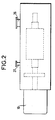
- the rotary machine shown which is in this case, a screw pump, dry, vacuum, comprises a first rotor 1 and a second rotor 2 with conjugated screws. These two rotors are mounted inside a casing-stator 3 which envelops them and in which they are supported by ball bearings 4, 5 for the first rotor 1 and 6, 7 for the second rotor 2.
- the shaft 8 of the first rotor 1 passes through the end of the stator casing 3 through a seal 9 and is driven in rotation by a drive motor 10.
- the second rotor 2 is driven in rotation via a synchronization gear comprising a pinion 11 mounted on the shaft 8 and a pinion 12 mounted on the shaft 13 of the second rotor 2.
- the synchronization gear 11-12 is located in the casing 3 inside a first chamber 14 containing a lubrication liquid 15.
- This first chamber 14 is separated from the part of the cavity 30 of the casing containing the two rotors 1 and 2, by a first partition 16 which carries the bearings 4 and 6. Seals 17 and 18 are arranged in this first partition 16 at the crossing of the shafts 8 and 13.
- the shafts 8 and 13 of the rotors successively pass through a third wall 19 and a second wall 20 delimiting between them two, a third chamber 21.
- a second chamber 31 is delimited between the second wall 20 and the end of the casing-stator.
- the third wall 19 laterally encloses the rotors 1 and 2 and it is crossed by the shafts 8 and 13 through seals 22 and 23.
- the second wall 20 is crossed by the shafts 8 and 13 through seals 24 and 25.
- the rolling bearings 5 and 7 are mounted in the second wall 20 between the seals 22 and 24 for the shaft 8 and between the seals 23 and 25 for the shaft 13.
- the rolling bearings 4 and 6 are mounted in the first partition between the seals 17, 18 and the first chamber 14.
- the casing-stator 3 is provided with a suction inlet 26 which communicates with the internal cavity 30 of the casing-stator through the third partition 19 and with a discharge outlet 27 which communicates with the internal cavity 30 of the casing- stator 3 through the first partition 16.
- the third chamber 21 communicates with the first chamber 14 by an auxiliary pipe 28 and the lubrication and cooling fluid 15 located in these two chambers is sucked by a circulation pump 47, located in a main pipe 29, and discharged into the second chamber 31 and from there into channels of circulation 32 of the stator and 33, 34 of the rotors.
- the stator circulation channel 32 ends at the other end of the machine in the first chamber 14 or, as shown in the drawing, directly in the auxiliary pipe 28, or main pipe 29, on the suction side.
- the circulation channels 33 and 34 of the rotors have discharge orifices 35 and 36 ending directly in the first chamber 14, orifices 37 and 38 ending in the third chamber 21 and projecting lubricant liquid on the bearings 5 and 7 and finally orifices 39 and 40, for the lubrication of bearings 4 and 6, located between seals 17-18 and bearings 4-6.
- the main pipe 29 includes a heat exchanger 41 cooled by a water circuit 42.
- Two temperature probes 43 and 44 are installed inside the stator housing 3, one of which, the probe 44, is placed as close as possible to the rotors 1 and 2, so as to measure the temperatures of the stator and the rotors .
- a control box 45 to which they are connected produces a control signal for the flow of the lubricating-coolant fluid 15 as a function of the difference in temperatures measured by the probes 43 and 44, this signal controlling the operation of a flow control valve. 46 located in main line 29.
- This insulation 48 has the additional advantage of ensuring sound insulation.
Landscapes
- Engineering & Computer Science (AREA)
- General Engineering & Computer Science (AREA)
- Mechanical Engineering (AREA)
- Applications Or Details Of Rotary Compressors (AREA)
- Rotary Pumps (AREA)
- Reciprocating Pumps (AREA)
- Electromagnetic Pumps, Or The Like (AREA)
- Details And Applications Of Rotary Liquid Pumps (AREA)
- Lubrication Of Internal Combustion Engines (AREA)
Claims (3)
- Drehende Maschine vom Schraubenpumpentyp, mit einem ersten Rotor (1) und einem zweiten Rotor (2), deren Schrauben komplementär sind und die über Lager (4 bis 7) in einem Statorgehäuse (3) untergebracht sind, das die Rotoren umgibt und einen mit dem Hohlraum (30), in dem die Rotoren sitzen, an einem Ende der Rotoren in Verbindung stehenden Saugeingang, sowie einen Druckausgang (27) aufweist, der mit diesem Hohlraum am anderen Ende der Rotoren in Verbindung steht, wobei der erste Rotor von einem Antriebsmotor (10) in Drehung versetzt wird und der zweite Rotor über ein in einer ersten an einem Ende des Gehäuses liegenden Kammer (14) untergebrachtes Synchrongetriebe (11, 12) angetrieben wird, wobei dieses Synchrongetriebe (11, 12) in ein Schmierfluid (15) eingetaucht ist und der Hohlraum (30) des Gehäuses mit den Rotoren gegenüber der ersten, das Getriebe (11, 12) enthaltenden Kammer (14) durch eine erste Wand (16) abgetrennt ist, die von den Wellen (8, 13) der Rotoren über Dichtungen (17, 18) durchquert wird, wobei die Wellen der Rotoren auch eine zweite Wand (20) über Dichtungen (24, 25) durchqueren, die auf Seiten des dem Getriebe abgewandten Rotorendes liegt, wobei die Maschine außerdem einen Hauptkanal (29) mit Pumpmitteln (47) aufweist, dessen erstes Ende in die erste Kammer (14) mündet, wobei die Rotoren Fluidumlaufkanäle aufweisen, die mit einem Ende in die erste Kammer (14) münden, wobei ein Wärmetauscher (41) in diesen Kanal eingebaut ist, um das Schmierfluid zu kühlen, dadurch gekennzeichnet, daß das Statorgehäuse (3) jenseits der zweiten Wand (20) eine zweite Kammer (31) aufweist, an die ein zweites Ende des Hauptkanals (29) angeschlossen ist, wobei die Kanäle der Rotoren an ihrem anderen Ende in diese zweite Kammer münden, daß das Statorgehäuse (3) außerdem Fluidumlaufkanäle (32) aufweist, die einerseits in die zweite Kammer (31) und andererseits in die erste Kammer (14) oder unmittelbar in den Hauptkanal (29) münden, und zwar in dem zwischen der ersten Kammer (14) und dem Wärmetauscher (41) liegenden Bereich.
- Drehende Maschine nach Anspruch 1, dadurch gekennzeichnet, daß das Statorgehäuse eine dritte Kammer (21) aufweist, die zwischen der zweiten Wand (20) und einer dritten Wand (19) liegt und seitlich die Rotoren einschließt, sowie von den Rotorwellen über Dichtungen (22, 23) durchquert wird, wobei Lager (5, 7), die die Rotoren tragen, in der zweiten oder der dritten Wand zwischen den Dichtungen angeordnet sind und ein Hilfskanal (28) die erste Kammer (14) mit der dritten Kammer (21) verbindet, wobei die Kanäle (33, 34) in den Rotoren zum Umlauf des Fluids einerseits Öffnungen (37, 38) besitzen, die in die dritte Kammer (21) münden, und andererseits Öffnungen (39, 40), die zwischen den die Rotoren tragenden in der ersten Wand (16) montierten Lagern (4, 6) und den Dichtungen (17, 18) münden, durch die die Wellen der Rotoren die erste Wand (16) durchqueren.
- Drehende Maschine nach einem der vorhergehenden Ansprüche, dadurch gekennzeichnet, daß zwei Temperatursonden (43, 44) im Inneren des Statorgehäuses angebracht sind, von denen die eine (44) möglichst nahe an den Rotoren liegt und die beide an einen Steuerkasten (45) angeschlossen sind, der ein Steuersignal erzeugt, das für die Steuerung eines in dem mit Pumpmitteln versehenen Kanal liegenden regelbaren Ventils (46) verwendet wird.
Priority Applications (1)
| Application Number | Priority Date | Filing Date | Title |
|---|---|---|---|
| AT89118212T ATE93010T1 (de) | 1988-10-07 | 1989-10-02 | Drehkolbenmaschine der art einer schraubenpumpe. |
Applications Claiming Priority (2)
| Application Number | Priority Date | Filing Date | Title |
|---|---|---|---|
| FR8813193A FR2637655B1 (fr) | 1988-10-07 | 1988-10-07 | Machine rotative du type pompe a vis |
| FR8813193 | 1988-10-07 |
Publications (3)
| Publication Number | Publication Date |
|---|---|
| EP0362757A2 EP0362757A2 (de) | 1990-04-11 |
| EP0362757A3 EP0362757A3 (en) | 1990-04-18 |
| EP0362757B1 true EP0362757B1 (de) | 1993-08-11 |
Family
ID=9370801
Family Applications (1)
| Application Number | Title | Priority Date | Filing Date |
|---|---|---|---|
| EP89118212A Expired - Lifetime EP0362757B1 (de) | 1988-10-07 | 1989-10-02 | Drehkolbenmaschine der Art einer Schraubenpumpe |
Country Status (7)
| Country | Link |
|---|---|
| US (1) | US4983106A (de) |
| EP (1) | EP0362757B1 (de) |
| JP (1) | JPH02149791A (de) |
| AT (1) | ATE93010T1 (de) |
| DE (1) | DE68908323T2 (de) |
| ES (1) | ES2042922T3 (de) |
| FR (1) | FR2637655B1 (de) |
Cited By (1)
| Publication number | Priority date | Publication date | Assignee | Title |
|---|---|---|---|---|
| CN109469618A (zh) * | 2018-11-29 | 2019-03-15 | 周焱春 | 一种螺杆空气压缩机 |
Families Citing this family (48)
| Publication number | Priority date | Publication date | Assignee | Title |
|---|---|---|---|---|
| JP2572566Y2 (ja) * | 1991-07-05 | 1998-05-25 | 株式会社 神戸製鋼所 | 空冷式オイルフリースクリュ圧縮機 |
| DE9209117U1 (de) * | 1992-07-09 | 1992-08-27 | PKL Verpackungssysteme GmbH, 5271 Linnich | Pumpe |
| US5626470A (en) * | 1996-04-10 | 1997-05-06 | Ingersoll-Rand Company | Method for providing lubricant to thrust bearing |
| DE19745616A1 (de) | 1997-10-10 | 1999-04-15 | Leybold Vakuum Gmbh | Gekühlte Schraubenvakuumpumpe |
| DE19745615A1 (de) | 1997-10-10 | 1999-04-15 | Leybold Vakuum Gmbh | Schraubenvakuumpumpe mit Rotoren |
| KR20010033628A (ko) * | 1997-12-30 | 2001-04-25 | 아뜰리에 부쉬 에스.에이. | 냉각 장치 |
| DE19800825A1 (de) * | 1998-01-02 | 1999-07-08 | Schacht Friedrich | Trockenverdichtende Schraubenspindelpumpe |
| DE19963170A1 (de) * | 1999-12-27 | 2001-06-28 | Leybold Vakuum Gmbh | Vakuumpumpe mit Wellendichtmitteln |
| US6394777B2 (en) * | 2000-01-07 | 2002-05-28 | The Nash Engineering Company | Cooling gas in a rotary screw type pump |
| FR2812040B1 (fr) * | 2000-07-18 | 2003-02-07 | Cit Alcatel | Carter monobloc pour pompe a vide |
| BE1013944A3 (nl) * | 2001-03-06 | 2003-01-14 | Atlas Copco Airpower Nv | Watergeinjecteerde schroefcompressor. |
| DE10156179A1 (de) * | 2001-11-15 | 2003-05-28 | Leybold Vakuum Gmbh | Kühlung einer Schraubenvakuumpumpe |
| DE10156180B4 (de) * | 2001-11-15 | 2015-10-15 | Oerlikon Leybold Vacuum Gmbh | Gekühlte Schraubenvakuumpumpe |
| CN1656316A (zh) * | 2002-05-20 | 2005-08-17 | Ts株式会社 | 真空泵 |
| DE10223869A1 (de) * | 2002-05-29 | 2003-12-11 | Leybold Vakuum Gmbh | Zwei-Wellen-Vakuumpumpe |
| GB0223769D0 (en) * | 2002-10-14 | 2002-11-20 | Boc Group Plc | A pump |
| TWI315388B (en) * | 2002-11-28 | 2009-10-01 | Ajinomoto Kk | Drum dryer |
| DE20302989U1 (de) * | 2003-02-24 | 2004-07-08 | Werner Rietschle Gmbh + Co. Kg | Drehkolbenpumpe |
| US6969242B2 (en) * | 2003-02-28 | 2005-11-29 | Carrier Corpoation | Compressor |
| US7682084B2 (en) * | 2003-07-18 | 2010-03-23 | Kobe Steel, Ltd. | Bearing and screw compressor |
| CN1871436A (zh) * | 2003-10-21 | 2006-11-29 | 纳博特斯克株式会社 | 旋转式干式真空泵 |
| DE102004056396A1 (de) * | 2004-11-23 | 2006-05-24 | Leybold Vacuum Gmbh | Zahnradanordnung |
| DE102004058056A1 (de) * | 2004-12-02 | 2006-06-08 | Leybold Vacuum Gmbh | Zahnradanordnung |
| DE102005012040A1 (de) * | 2005-03-16 | 2006-09-21 | Gebr. Becker Gmbh & Co Kg | Rotor und Schraubenvakuumpumpe |
| GB0510892D0 (en) * | 2005-05-27 | 2005-07-06 | Boc Group Plc | Vacuum pump |
| JP4521344B2 (ja) * | 2005-09-30 | 2010-08-11 | 株式会社日立産機システム | 油冷式スクリュー圧縮機 |
| JP2007170341A (ja) * | 2005-12-26 | 2007-07-05 | Toyota Industries Corp | スクリュー式流体機械 |
| JP4717048B2 (ja) * | 2007-10-26 | 2011-07-06 | 株式会社神戸製鋼所 | スクリュ圧縮機 |
| JP5103246B2 (ja) * | 2008-01-24 | 2012-12-19 | 株式会社神戸製鋼所 | スクリュ圧縮機 |
| WO2010006663A1 (de) * | 2008-07-18 | 2010-01-21 | Ralf Steffens | Kühlung einer schraubenspindelpumpe |
| CN102177346B (zh) * | 2008-10-10 | 2014-01-15 | 株式会社爱发科 | 干泵 |
| JP5426565B2 (ja) | 2008-10-22 | 2014-02-26 | 株式会社前川製作所 | 給油式スクリュー圧縮機 |
| US9435383B2 (en) | 2011-09-30 | 2016-09-06 | Moyno, Inc. | Universal joint with cooling system |
| CN103644115A (zh) * | 2013-08-29 | 2014-03-19 | 钟文填 | 双圆弧螺杆泵 |
| DE212016000070U1 (de) | 2015-04-06 | 2017-11-14 | Trane International Inc. | Aktives Abstandsmanagement bei Schraubenkompressoren |
| CN105003433A (zh) * | 2015-08-17 | 2015-10-28 | 山东百惠精工机械股份有限公司 | 一种强制风冷罗茨鼓风机 |
| KR101712962B1 (ko) * | 2015-09-24 | 2017-03-07 | 이인철 | 냉각장치를 갖춘 진공펌프 |
| CN105715513B (zh) * | 2016-04-07 | 2017-10-24 | 台州环球真空设备制造有限公司 | 风冷式真空泵 |
| CN106704176B (zh) * | 2016-12-02 | 2018-11-06 | 马德宝真空设备集团有限公司 | 一种罗茨泵的冷却系统 |
| WO2019210053A1 (en) * | 2018-04-27 | 2019-10-31 | Carrier Corporation | Screw compressor with external motor rotor |
| FR3087504B1 (fr) * | 2018-10-17 | 2020-10-30 | Pfeiffer Vacuum | Procede de controle de la temperature d’une pompe a vide, pompe a vide et installation associees |
| CN109538479A (zh) * | 2019-01-21 | 2019-03-29 | 济南冶金化工设备有限公司 | 水蒸气压缩机 |
| US11448220B2 (en) * | 2019-09-27 | 2022-09-20 | Ingersoll-Rand Industrial U.S., Inc. | Airend having a lubricant flow valve and controller |
| WO2021253060A1 (en) * | 2020-06-10 | 2021-12-16 | CILLIE, Willem, Isaac | Rotor assembly |
| CN111677663B (zh) * | 2020-06-23 | 2022-01-11 | 江苏亚太工业泵科技发展有限公司 | 一种高压高效真空节能泵 |
| CN114448175B (zh) * | 2022-02-11 | 2024-06-18 | 华为数字能源技术有限公司 | 动力总成、控制动力总成的冷却的方法以及车辆 |
| CN114412785B (zh) | 2022-03-28 | 2022-07-15 | 天津捷盛东辉保鲜科技有限公司 | 宽温域恒温转子型双螺杆制冷压缩机 |
| US20240401693A1 (en) * | 2023-05-31 | 2024-12-05 | Fca Us Llc | Lubrication cooling system for an electric drive module and efficient thermal management |
Citations (1)
| Publication number | Priority date | Publication date | Assignee | Title |
|---|---|---|---|---|
| GB785860A (en) * | 1955-01-17 | 1957-11-06 | Manfred Dunkel | Improvements in or relating to rotary piston blowers |
Family Cites Families (10)
| Publication number | Priority date | Publication date | Assignee | Title |
|---|---|---|---|---|
| US2938664A (en) * | 1955-01-17 | 1960-05-31 | Leybold S Nachfolger Fa E | Pump |
| BE549281A (de) * | 1956-04-30 | |||
| JPS4947208U (de) * | 1972-07-27 | 1974-04-25 | ||
| US3913346A (en) * | 1974-05-30 | 1975-10-21 | Dunham Bush Inc | Liquid refrigerant injection system for hermetic electric motor driven helical screw compressor |
| US3961862A (en) * | 1975-04-24 | 1976-06-08 | Gardner-Denver Company | Compressor control system |
| US4125210A (en) * | 1977-07-26 | 1978-11-14 | Lawrence Peska Associates, Inc. | Attachment for paint cans |
| US4228657A (en) * | 1978-08-04 | 1980-10-21 | Hughes Aircraft Company | Regenerative screw expander |
| US4420291A (en) * | 1979-01-05 | 1983-12-13 | Maryland Cup Corporation | Dynamic cooler apparatus for molten thermoplastic material |
| JPS59115492A (ja) * | 1982-12-22 | 1984-07-03 | Hitachi Ltd | 無給油式スクリユ−圧縮機 |
| JPS6241986A (ja) * | 1986-08-29 | 1987-02-23 | Hitachi Ltd | オイルフリースクリユー圧縮機結合体 |
-
1988
- 1988-10-07 FR FR8813193A patent/FR2637655B1/fr not_active Expired - Fee Related
-
1989
- 1989-10-02 DE DE89118212T patent/DE68908323T2/de not_active Expired - Fee Related
- 1989-10-02 ES ES89118212T patent/ES2042922T3/es not_active Expired - Lifetime
- 1989-10-02 EP EP89118212A patent/EP0362757B1/de not_active Expired - Lifetime
- 1989-10-02 AT AT89118212T patent/ATE93010T1/de not_active IP Right Cessation
- 1989-10-04 JP JP1259887A patent/JPH02149791A/ja active Pending
- 1989-10-04 US US07/417,115 patent/US4983106A/en not_active Expired - Lifetime
Patent Citations (1)
| Publication number | Priority date | Publication date | Assignee | Title |
|---|---|---|---|---|
| GB785860A (en) * | 1955-01-17 | 1957-11-06 | Manfred Dunkel | Improvements in or relating to rotary piston blowers |
Cited By (1)
| Publication number | Priority date | Publication date | Assignee | Title |
|---|---|---|---|---|
| CN109469618A (zh) * | 2018-11-29 | 2019-03-15 | 周焱春 | 一种螺杆空气压缩机 |
Also Published As
| Publication number | Publication date |
|---|---|
| ATE93010T1 (de) | 1993-08-15 |
| FR2637655A1 (fr) | 1990-04-13 |
| ES2042922T3 (es) | 1993-12-16 |
| US4983106A (en) | 1991-01-08 |
| DE68908323D1 (de) | 1993-09-16 |
| EP0362757A3 (en) | 1990-04-18 |
| FR2637655B1 (fr) | 1994-01-28 |
| DE68908323T2 (de) | 1993-12-09 |
| JPH02149791A (ja) | 1990-06-08 |
| EP0362757A2 (de) | 1990-04-11 |
Similar Documents
| Publication | Publication Date | Title |
|---|---|---|
| EP0362757B1 (de) | Drehkolbenmaschine der Art einer Schraubenpumpe | |
| KR100682586B1 (ko) | 건식-압축스크류펌프 | |
| BE1014892A5 (fr) | Compresseur a vis sans huile. | |
| FR2647853A1 (fr) | Pompe primaire seche a deux etages | |
| EP0368122B1 (de) | Mehrstufige Roots-Vakuumpumpe | |
| EP0000131B1 (de) | Verfahren und Vorrichtung zur Schmierung von Kompressoren | |
| EP0499504A1 (de) | Turbomaschine - vom Typ Kompressor oder Turbine - zur Verdichtung oder Entspannung eines gefährlichen Gases | |
| WO2006125909A1 (fr) | Compresseur frigorifique a spirales | |
| EP0882892A1 (de) | Spiralmaschine | |
| EP3921515B1 (de) | Mehrstufiges pumpengehäuse und mehrstufige gaspumpe | |
| FR2689185A1 (fr) | Ensemble à pompe à huile pour moteur. | |
| FR2942656A1 (fr) | Dispositif de separation de lubrifiant d'un melange lubrifiant-gaz frigorigene | |
| CH343727A (fr) | Dispositif pour assurer l'étanchéité autour d'un arbre rotatif traversant une paroi | |
| FR2468770A1 (fr) | Compresseur a piston roulant | |
| FR2729437A1 (fr) | Pompe a dispositif de nettoyage en place | |
| WO2024165119A1 (fr) | Machine de traitement de fluide à étanchéité améliorée | |
| RU958U1 (ru) | Жидкостно-кольцевой вакуум-насос | |
| FR2508982A1 (fr) | Groupe motopompe comportant une turbine d'entrainement d'une pompe principale | |
| FR2497882A1 (fr) | Perfectionnements apportes aux pompes rotatives | |
| KR910002867Y1 (ko) | 루쯔 송풍기 | |
| FR2756877A1 (fr) | Compresseur hermetique destine a la circulation de gaz | |
| CH365477A (fr) | Dispositif pour obturer un orifice ménagé dans une paroi et traversé par une arbre rotatif | |
| FR2508981A1 (fr) | Ensemble motopompe comportant une turbine d'entrainement d'une pompe principale | |
| BE487900A (de) | ||
| BE630307A (de) |
Legal Events
| Date | Code | Title | Description |
|---|---|---|---|
| PUAI | Public reference made under article 153(3) epc to a published international application that has entered the european phase |
Free format text: ORIGINAL CODE: 0009012 |
|
| PUAL | Search report despatched |
Free format text: ORIGINAL CODE: 0009013 |
|
| AK | Designated contracting states |
Kind code of ref document: A2 Designated state(s): AT BE CH DE ES FR GB GR IT LI LU NL SE |
|
| AK | Designated contracting states |
Kind code of ref document: A3 Designated state(s): AT BE CH DE ES FR GB GR IT LI LU NL SE |
|
| RAP1 | Party data changed (applicant data changed or rights of an application transferred) |
Owner name: ALCATEL CIT |
|
| RIN1 | Information on inventor provided before grant (corrected) |
Inventor name: RIACH, ALLAN Inventor name: WRIGHT, DAN Inventor name: CRINQUETTE, JEAN-MARIE Inventor name: LONG, JACQUES Inventor name: SIBUET, RENE |
|
| 17P | Request for examination filed |
Effective date: 19901015 |
|
| 17Q | First examination report despatched |
Effective date: 19911212 |
|
| GRAA | (expected) grant |
Free format text: ORIGINAL CODE: 0009210 |
|
| AK | Designated contracting states |
Kind code of ref document: B1 Designated state(s): AT BE CH DE ES FR GB GR IT LI LU NL SE |
|
| PG25 | Lapsed in a contracting state [announced via postgrant information from national office to epo] |
Ref country code: SE Effective date: 19930811 Ref country code: GR Free format text: LAPSE BECAUSE OF FAILURE TO SUBMIT A TRANSLATION OF THE DESCRIPTION OR TO PAY THE FEE WITHIN THE PRESCRIBED TIME-LIMIT Effective date: 19930811 Ref country code: AT Effective date: 19930811 |
|
| REF | Corresponds to: |
Ref document number: 93010 Country of ref document: AT Date of ref document: 19930815 Kind code of ref document: T |
|
| GBT | Gb: translation of ep patent filed (gb section 77(6)(a)/1977) |
Effective date: 19930810 |
|
| REF | Corresponds to: |
Ref document number: 68908323 Country of ref document: DE Date of ref document: 19930916 |
|
| ITF | It: translation for a ep patent filed | ||
| PG25 | Lapsed in a contracting state [announced via postgrant information from national office to epo] |
Ref country code: LU Free format text: LAPSE BECAUSE OF NON-PAYMENT OF DUE FEES Effective date: 19931031 Ref country code: BE Effective date: 19931031 |
|
| REG | Reference to a national code |
Ref country code: ES Ref legal event code: FG2A Ref document number: 2042922 Country of ref document: ES Kind code of ref document: T3 |
|
| BERE | Be: lapsed |
Owner name: ALCATEL CIT Effective date: 19931031 |
|
| PLBE | No opposition filed within time limit |
Free format text: ORIGINAL CODE: 0009261 |
|
| STAA | Information on the status of an ep patent application or granted ep patent |
Free format text: STATUS: NO OPPOSITION FILED WITHIN TIME LIMIT |
|
| 26N | No opposition filed | ||
| PGFP | Annual fee paid to national office [announced via postgrant information from national office to epo] |
Ref country code: ES Payment date: 19950906 Year of fee payment: 7 |
|
| PGFP | Annual fee paid to national office [announced via postgrant information from national office to epo] |
Ref country code: NL Payment date: 19951031 Year of fee payment: 7 |
|
| PG25 | Lapsed in a contracting state [announced via postgrant information from national office to epo] |
Ref country code: ES Free format text: LAPSE BECAUSE OF THE APPLICANT RENOUNCES Effective date: 19961003 |
|
| PG25 | Lapsed in a contracting state [announced via postgrant information from national office to epo] |
Ref country code: NL Effective date: 19970501 |
|
| NLV4 | Nl: lapsed or anulled due to non-payment of the annual fee |
Effective date: 19970501 |
|
| REG | Reference to a national code |
Ref country code: ES Ref legal event code: FD2A Effective date: 19991007 |
|
| REG | Reference to a national code |
Ref country code: GB Ref legal event code: IF02 |
|
| PGFP | Annual fee paid to national office [announced via postgrant information from national office to epo] |
Ref country code: GB Payment date: 20030929 Year of fee payment: 15 |
|
| PGFP | Annual fee paid to national office [announced via postgrant information from national office to epo] |
Ref country code: CH Payment date: 20031001 Year of fee payment: 15 |
|
| PGFP | Annual fee paid to national office [announced via postgrant information from national office to epo] |
Ref country code: FR Payment date: 20031009 Year of fee payment: 15 |
|
| PGFP | Annual fee paid to national office [announced via postgrant information from national office to epo] |
Ref country code: DE Payment date: 20031010 Year of fee payment: 15 |
|
| PG25 | Lapsed in a contracting state [announced via postgrant information from national office to epo] |
Ref country code: GB Free format text: LAPSE BECAUSE OF NON-PAYMENT OF DUE FEES Effective date: 20041002 |
|
| PG25 | Lapsed in a contracting state [announced via postgrant information from national office to epo] |
Ref country code: LI Free format text: LAPSE BECAUSE OF NON-PAYMENT OF DUE FEES Effective date: 20041031 Ref country code: CH Free format text: LAPSE BECAUSE OF NON-PAYMENT OF DUE FEES Effective date: 20041031 |
|
| PG25 | Lapsed in a contracting state [announced via postgrant information from national office to epo] |
Ref country code: DE Free format text: LAPSE BECAUSE OF NON-PAYMENT OF DUE FEES Effective date: 20050503 |
|
| GBPC | Gb: european patent ceased through non-payment of renewal fee |
Effective date: 20041002 |
|
| REG | Reference to a national code |
Ref country code: CH Ref legal event code: PL |
|
| PG25 | Lapsed in a contracting state [announced via postgrant information from national office to epo] |
Ref country code: FR Free format text: LAPSE BECAUSE OF NON-PAYMENT OF DUE FEES Effective date: 20050630 |
|
| REG | Reference to a national code |
Ref country code: FR Ref legal event code: ST |
|
| PG25 | Lapsed in a contracting state [announced via postgrant information from national office to epo] |
Ref country code: IT Free format text: LAPSE BECAUSE OF NON-PAYMENT OF DUE FEES;WARNING: LAPSES OF ITALIAN PATENTS WITH EFFECTIVE DATE BEFORE 2007 MAY HAVE OCCURRED AT ANY TIME BEFORE 2007. THE CORRECT EFFECTIVE DATE MAY BE DIFFERENT FROM THE ONE RECORDED. Effective date: 20051002 |