EP0362766B1 - Verstellgerät für eine ophthalmologische Behandlungsvorrichtung - Google Patents
Verstellgerät für eine ophthalmologische Behandlungsvorrichtung Download PDFInfo
- Publication number
- EP0362766B1 EP0362766B1 EP19890118232 EP89118232A EP0362766B1 EP 0362766 B1 EP0362766 B1 EP 0362766B1 EP 19890118232 EP19890118232 EP 19890118232 EP 89118232 A EP89118232 A EP 89118232A EP 0362766 B1 EP0362766 B1 EP 0362766B1
- Authority
- EP
- European Patent Office
- Prior art keywords
- hand
- finger
- control arrangement
- practitioner
- fact
- Prior art date
- Legal status (The legal status is an assumption and is not a legal conclusion. Google has not performed a legal analysis and makes no representation as to the accuracy of the status listed.)
- Expired - Lifetime
Links
- 210000003811 finger Anatomy 0.000 claims description 44
- 210000003813 thumb Anatomy 0.000 claims description 10
- 238000010304 firing Methods 0.000 claims description 3
- 230000000630 rising effect Effects 0.000 claims description 2
- 210000000707 wrist Anatomy 0.000 claims description 2
- 230000001747 exhibiting effect Effects 0.000 claims 1
- 238000005096 rolling process Methods 0.000 description 2
- RZVAJINKPMORJF-UHFFFAOYSA-N Acetaminophen Chemical compound CC(=O)NC1=CC=C(O)C=C1 RZVAJINKPMORJF-UHFFFAOYSA-N 0.000 description 1
- 244000141359 Malus pumila Species 0.000 description 1
- 235000021016 apples Nutrition 0.000 description 1
- 230000001427 coherent effect Effects 0.000 description 1
- 239000012141 concentrate Substances 0.000 description 1
- 238000006073 displacement reaction Methods 0.000 description 1
- 230000000694 effects Effects 0.000 description 1
Images

Classifications
-
- A—HUMAN NECESSITIES
- A61—MEDICAL OR VETERINARY SCIENCE; HYGIENE
- A61B—DIAGNOSIS; SURGERY; IDENTIFICATION
- A61B3/00—Apparatus for testing the eyes; Instruments for examining the eyes
- A61B3/0075—Apparatus for testing the eyes; Instruments for examining the eyes provided with adjusting devices, e.g. operated by control lever
Definitions
- the present invention relates to a device for controlling an ophthalmological treatment apparatus, said apparatus comprising at least one power laser beam having a focal point of concentration of said beam capable of acting, on the firing order of a practitioner, at a determined location in the eye of a patient, location defined by first, second and third orthogonal dimensional coordinates, said control device comprising a housing on which a hand of a practitioner can rest, said housing being provided first means for fixing the focal point according to the first coordinate, second means for fixing the focal point in a plane according to the second and third coordinates and third means for triggering the laser shot when said three coordinates are reached, said first, second and third means being arranged in such a way that they can each be controlled by the fingers of the same hand.
- the device essentially comprises a first light source which emits a power laser beam intended for treatment proper and a second light source which emits a beam of visible coherent light of low power arranged to envelop the power beam.
- the beams mentioned then pass through a converging lens which concentrates them in a focal point which is the processing point, the visible light beam being present to allow to locate with precision the place where is the focus of the power beam.
- the focal point is observed by a practitioner through an eyepiece (or binocular) while the ocular cavity is illuminated by an auxiliary source of light. When the desired location for treatment is reached, the practitioner controls the laser shot.
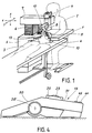
- the devices of the prior art are presented in broad outline as shown in FIG. 1.
- the treatment device comprises a table 1 in front of which a practitioner sits 2.
- a patient 3 On the other side of the table takes a patient 3, here lying on a bed 4 precisely fitting into the table.
- the patient is seated and rests his head on a chin rest attached to the table.
- the device is designed so that the patient's head is immobilized relative to said device.
- Figure 1 also shows a box 5 which supports the table.
- This support generally contains the sources giving rise to the beams of power and visible light which were discussed above.
- These beams are conveyed inside the patient's eye by a column 6 and a movable arm 7, the latter carrying an exit optic 8 capable of focusing the beams at a point which is to be brought to a very precise place in the patient's eye, a point which is observed by the practitioner through the binocular 9.
- the arm 7 can move according to the three orthogonal coordinates X, Y and Z.
- control device 13 comprises four separate members respectively controlling the displacements X, Y and Z and the laser shot, the first three members being able to be rollers than it operates in both directions and the fourth member can be a simple push button.
- This provision is inconvenient because it forces the practitioner to memorize the location of the rollers and the functions assigned to them with the risk of error or loss of time that such a system can result, since the practitioner's view is entirely occupied with observing the cavity of the eye to be treated and must not be distracted to check, for example, whether the correct control member is actuated.
- the present invention is characterized either by the fact that the first and second means are a ball capable of being respectively pressed and rolled by a first finger and that the third means is a pusher capable to be pressed by a second finger, either by the fact that the first means is a roulette capable of being turned by a first finger, that the second means is a ball capable of being rolled by a second finger and that the third medium is a pusher capable of being pressed by a third finger.
- a control device associating a ball with a computer keyboard is shown in document GB-A-2 154 306. In this document it is not indicated that the ball can be pressed or associated with a wheel to fix the point focal according to a first coordinate.
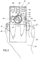
- the device 13 is a housing on which has been shown a hand of a practitioner.
- the device is provided with a first means for fixing the focal point of the laser beam according to a first coordinate.
- the figure shows that this first means here is a roller 20 which can be turned by a first finger 21, in this case the thumb of the right hand 22.
- Figure 2 also shows that the device is provided with a second means for fixing the focal point of the laser beam in a plane according to second and third coordinates.
- This second means is here a ball 23 capable of being rolled by a second finger 24, ie the index finger of the right hand 22.
- FIG. 2 shows that the device comprises a third means for triggering the laser shot as soon as said three contact details have been reached by actuation of the first and second means.
- This third means is here in the form of a pusher 25 capable of being actuated by a third finger 26, ie the middle finger of the right hand 22.
- a third finger 26 ie the middle finger of the right hand 22.
- the first, second and third means are arranged in such a way that they can each be controlled by a finger different from the same hand.
- the device uses only two fingers to bring the focal point of the beam to the desired location and this thanks to the use of a single means (the ball) to position the focal point in a plane.
- the use of the index to search for two co-ordinates in a plane is particularly advantageous because, on the one hand, of the excellent mobility that this finger presents in comparison with the mobility of the other fingers of the hand and, on the other hand, the independence of action of this finger in relation to the others.
- the use of the thumb for the search for a single coordinate is also judicious, this finger being less mobile, but lending itself well to the rolling action that it is asked to perform on the roulette.
- the use of the middle finger for laser shooting is advantageous especially because of its position well suited to actuate a push button.
- FIG. 2 shows that the caster 20 and the pusher 25 are split by a second caster 20 ′ and a second pusher 25 ′.
- This arrangement allows the control device to be used also with the left hand as shown in FIG. 3.
- the left hand 22 ′ by its thumb 21 ′, its index finger 24 ′ and its middle finger 26 ′ respectively controls the wheel 20 ′, ball 23 and pusher 25 ′.
- Figure 3 the same advantageous arrangement of controls, also arranged quite logically but for the left hand this time.
- FIG. 4 is a view according to the arrow IV of FIG. 2, we find on the device 13 the same three control means which have been described above, that is to say -to say in order the roulette 20 ′, the ball 23 and the pusher 25.
- This view also shows an additional feature of the invention which consists in breaking the face against which the hand comes to rest in a first rising zone 30 capable of serving as a support for the wrist of the hand and in a second descending zone 31 on which are arranged the ball 23 and the pushers 25, 25 ′ controlled respectively by the index and middle finger of the hand (not shown here) .
- This broken face device is particularly well suited for supporting the hand and contributes, if we add the judicious arrangement of the controls themselves, to a particularly well chosen ergonomics, facilitating rapid action, free from error and reducing the both physical and intellectual fatigue.
- Figures 2, 3 and 4 show that the control device may further comprise fourth means for quickly reaching an area in the environment close to where the shooting is to take place. They are in fact pushers allowing a rough preset according to the three coordinates.
- the pushers 40 and 41 allow a rapid search for the first coordinate. The same goes for pushers 42, 43 and 44, 45 which allow the same quick search, but for the second and third coordinates, respectively.
- the means to move the focal point in a plane using a single finger here consists in using a ball which can roll freely around its center.
- a ball which can roll freely around its center.
- the use of a joystick poses problems of position stability and accuracy.
- FIG. 2 shows that the ball has been assigned the coordinates X and Y.
- the ball 23 drives two wheels 50, 54 arranged orthogonally to one another .
- the figure shows that the wheel 50 drives a disc 51.
- This disc is pierced with slots which allow the light emitted by a lamp 52.
- On the other side of the disc is a photoelectric sensor which receives light passing through the slits.
- the electrical pulses from the sensor control a power electronics which in turn controls, for example, a stepping motor.
- This motor controls the arm 7 of the ophthalmological device shown in FIG. 1 and this according to the Y coordinate.
- a similar device is used for moving the arm according to the X coordinate, starting from the wheel 54.
- the Z coordinate is controlled by the thumb 21 acting on the caster 20.
- the angle of rotation of the caster can also be converted into electrical pulses as explained above.
- the ball system able to move a point in a plane is known today and is used for example in some personal computers (PC).
- PC personal computers
- the system is reversed compared to that described here, that is to say that it is not a finger which moves the ball, but the hand which moves the case on a table, the ball being under the housing and rolling when the housing is moved.
- This system is commonly called “mouse” and is described in particular in the review “Mini & Micros", No. 305 / June 22, 1988.
- Logimouse marketed by Logitech SA, CH-1143 Apples.
- the mouse system has the disadvantage of requiring a lot of space for the excursion of the case on the table and getting dirty quickly.
- the ball 23 described here is used to move the focal point in an XY plane. We can see, however, that it could also be used to move this point along the Z coordinate. This additional function can easily be fulfilled, if we add to the ball a possibility of sinking which can act on a contact, itself putting in operation an arm drive motor in the Z coordinate. In these conditions, a single finger of the hand is sufficient to control the arm in three directions, the index 24, 24 ′ for example. In these conditions also, the firing function can be fulfilled either by the thumb 21, 21 ′, or by the middle finger 26, 26 ′.
- the description which has just been made is based on a treatment device where the patient is lying.
- the movement controlled by the ball is then carried out in a plane perpendicular to the vertical. If the patient is seated, it will be understood that the movement controlled by the ball must be done in a plane parallel to the vertical.
- the control device will be equipped, if necessary, with a system of permutation of the coordinates.
Landscapes
- Life Sciences & Earth Sciences (AREA)
- Health & Medical Sciences (AREA)
- Medical Informatics (AREA)
- Biophysics (AREA)
- Ophthalmology & Optometry (AREA)
- Engineering & Computer Science (AREA)
- Biomedical Technology (AREA)
- Heart & Thoracic Surgery (AREA)
- Physics & Mathematics (AREA)
- Molecular Biology (AREA)
- Surgery (AREA)
- Animal Behavior & Ethology (AREA)
- General Health & Medical Sciences (AREA)
- Public Health (AREA)
- Veterinary Medicine (AREA)
- Laser Surgery Devices (AREA)
- Eye Examination Apparatus (AREA)
- Radiation-Therapy Devices (AREA)
Claims (8)
- Steuervorrichtung (13) eines ophthalmologischen Behandlungsgerätes, das mindestens einen Leistungslaserstrahl umfaßt mit einem Konzentrationsbrennpunkt, mittels dem bei Auslösung durch einen Praktiker (2) an einer bestimmten Stelle des Auges eines Patienten (3) eingewirkt werden kann, welche Stelle definiert ist durch erste, zweite und dritte orthogonale räumliche Koordinaten, welche Steuervorrichtung ein Gehäuse umfaßt, auf dem eine Hand (22, 22') eines Praktikers ruhen kann, welches Gehäuse mit einem ersten Mittel versehen ist zum Festlegen des Brennpunktes gemäß der ersten Koordinate, mit einem zweiten Mittel zum Festlegen des Brennpunktes in einer Ebene gemäß der zweiten und dritten Koordinate und einem dritten Mittel zum Auslösen des Laserschusses, wenn die drei Koordinaten erreicht sind, welche Mittel derart angeordnet sind, daß jedes von ihnen von den Fingern derselben Hand betätigbar ist, dadurch gekennzeichnet, daß das erste und zweite Mittel eine Kugel (23) sind, die eindrückbar bzw. rollbar ist mittels eines ersten Fingers und daß das dritte Mittel ein Taster (25, 25') ist, der von einem zweiten Finger eindrückbar ist.
- Steuervorrichtung nach Anspruch 1, dadurch gekennzeichnet, daß die ersten, zweiten und dritten Mittel derart ausgebildet sind, daß sie von dem Zeigefinger (24, 24') bzw. dem Daumen (21, 21') oder dem Mittelfinger (26, 26') der Hand des Praktikers betätigbar sind.
- Steuervorrichtung (13) eines ophthalmologischen Behandlungsgerätes, das mindestens einen Leistungslaserstrahl mit einem Konzentrationsbrennpunkt aufweist, der bei Auslösung durch einen Praktiker (2) an einer bestimmten Stelle des Auges eines Patienten (3) einwirkt, welche Stelle definiert ist durch erste, zweite und dritte orthogonale räumliche Koordinaten, welche Steuervorrichtung ein Gehäuse umfaßt, auf dem eine Hand (22, 22') eines Praktikers ruhen kann, welches Gehäuse mit einem ersten Mittel versehen ist zum Festlegen des Brennpunktes gemäß der ersten Koordinate, mit einem zweiten Mittel zum Festlegen des Brennpunktes in einer Ebene entsprechend der zweiten und dritten Koordinate und einem dritten Mittel zum Auslösen des Laserschusses, wenn die drei Koordinaten erreicht sind, welche Mittel derart ausgebildet sind, daß jedes von ihnen von den Fingern derselben Hand betätigbar ist, dadurch gekennzeichnet, daß das erste Mittel eine Rolle (20, 20') ist, die von einem ersten Finger drehbar ist, daß das zweite Mittel eine Kugel (23) ist, die von einem zweiten Finger rollbar ist und daß das dritte Mittel ein Taster (25, 25') ist, der von einem dritten Finger eindrückbar ist.
- Steuervorrichtung nach Anspruch 3, dadurch gekennzeichnet, daß die ersten, zweiten und dritten Mittel derart ausgebildet sind, daß sie von dem Daumen (21, 21'), dem Zeigefinger (24, 24') bzw. dem Mittelfinger (26, 26') der Hand des Praktikers betätigbar sind.
- Steuervorrichtung nach Anspruch 1 oder Anspruch 3, dadurch gekennzeichnet, daß sie ferner vierte Mittel (40 bis 45) umfaßt zum schnellen Erreichen einer Zone, die sich in der nahen Umgebung der Stelle befindet, wo der Schuß stattfinden soll.
- Steuervorrichtung nach Anspruch 1 oder Anspruch 3, dadurch gekennzeichnet, daß die ersten, zweiten und dritten Mittel so angeordnet sind, daß sie sowohl von der rechten Hand (22) wie auch der linken Hand (22') des Praktikers betätigbar sind.
- Steuervorrichtung nach Anspruch 4, dadurch gekennzeichnet, daß das Gehäuse eine parallelepipedische Form aufweist, die auf der Seite, auf der die Hand sich abstützen kann, eine Kugel (23) aufweist, die vom Zeigefinger der Hand rollbar ist zum Festlegen der zweiten und dritten Koordinaten, sowie zwei Taster (25, 25') aufweist, die beidseits der Kugel angeordnet sind zum Steuern des Laserschusses durch den Mittelfinger der Hand, welches Gehäuse auf jeder Seite ihrer Seitenflächen eine Rolle (20, 20') aufweist, die von dem Daumen der Hand betätigbar ist, um die erste Koordinate festzulegen.
- Steuervorrichtung nach Anspruch 7, dadurch gekennzeichnet, daß die genannte Seite abgeknickt ist und eine erste ansteigende Zone (30) aufweist, die als Auflage für das Gelenk der Hand dienen kann, und eine zweite absteigende Zone (31) aufweist, auf der die Kugel und die beiden Taster angeordnet sind.
Priority Applications (1)
| Application Number | Priority Date | Filing Date | Title |
|---|---|---|---|
| AT89118232T ATE99145T1 (de) | 1988-10-06 | 1989-10-02 | Verstellgeraet fuer eine ophthalmologische behandlungsvorrichtung. |
Applications Claiming Priority (4)
| Application Number | Priority Date | Filing Date | Title |
|---|---|---|---|
| CH3744/88 | 1988-10-06 | ||
| CH3744/88A CH676420A5 (de) | 1988-10-06 | 1988-10-06 | |
| FR8813402 | 1988-10-10 | ||
| FR8813402A FR2637704B1 (fr) | 1988-10-10 | 1988-10-10 | Dispositif de commande d'un appareil de traitement ophtalmologique |
Publications (2)
| Publication Number | Publication Date |
|---|---|
| EP0362766A1 EP0362766A1 (de) | 1990-04-11 |
| EP0362766B1 true EP0362766B1 (de) | 1993-12-29 |
Family
ID=25693753
Family Applications (1)
| Application Number | Title | Priority Date | Filing Date |
|---|---|---|---|
| EP19890118232 Expired - Lifetime EP0362766B1 (de) | 1988-10-06 | 1989-10-02 | Verstellgerät für eine ophthalmologische Behandlungsvorrichtung |
Country Status (2)
| Country | Link |
|---|---|
| EP (1) | EP0362766B1 (de) |
| DE (1) | DE68911824T2 (de) |
Family Cites Families (4)
| Publication number | Priority date | Publication date | Assignee | Title |
|---|---|---|---|---|
| US4470320A (en) * | 1981-11-12 | 1984-09-11 | Wico Corporation | Joystick assembly with wear member |
| FR2524298A1 (fr) * | 1982-04-01 | 1983-10-07 | Essilor Int | Appareil de chirurgie ophtalmologique a laser |
| CH655809A5 (fr) * | 1984-02-16 | 1986-05-15 | Depraz S A | Dispositif d'introduction de donnees graphiques dans une calculatrice. |
| DE3601022A1 (de) * | 1986-01-16 | 1987-07-23 | Zeiss Carl Fa | Vorrichtung zur feineinstellung eines auf einer basis angeordneten instrumentes in allen drei raumrichtungen |
-
1989
- 1989-10-02 DE DE1989611824 patent/DE68911824T2/de not_active Expired - Fee Related
- 1989-10-02 EP EP19890118232 patent/EP0362766B1/de not_active Expired - Lifetime
Also Published As
| Publication number | Publication date |
|---|---|
| EP0362766A1 (de) | 1990-04-11 |
| DE68911824D1 (de) | 1994-02-10 |
| DE68911824T2 (de) | 1994-07-28 |
Similar Documents
| Publication | Publication Date | Title |
|---|---|---|
| CH676420A5 (de) | ||
| CN112638233B (zh) | 基于家庭的眼科应用的微型移动低成本光学相干断层扫描系统 | |
| EP0074289A1 (de) | Steuerknüppel für elektronische Spiele | |
| EP0091334B1 (de) | Vorrichtung zur Augenoperation mittels Laserstrahl | |
| CA1301854C (fr) | Systeme optique et appareil chirurgical comportant ledit systeme | |
| EP1079325B1 (de) | Uhr mit berührungsloser Steuervorrichtung für eine Computer-Maus | |
| FR2876813A1 (fr) | Dispositif de commande de jeu video a organe de commande a boule roulante integre. | |
| EP3754436B1 (de) | Uhr, insbesondere taschenuhr, die mindestens mit einem deckel ausgestattet ist | |
| EP2073078A1 (de) | Bistabiler hammer für chronographenmechanismus | |
| EP2269119B1 (de) | Stossdämpfereinrichtung für das steuerglied einer uhr | |
| WO2020115249A1 (fr) | Dispositif médical pour la chirurgie de l'oeil | |
| FR2637704A1 (fr) | Dispositif de commande d'un appareil de traitement ophtalmologique | |
| EP0044770B1 (de) | Mit einem Mikrorechner ausgerüstetes objektives Refraktometer | |
| EP0362766A1 (de) | Verstellgerät für eine ophthalmologische Behandlungsvorrichtung | |
| EP0604283A1 (de) | Vorrichtung zur Halterung und Führung eines Kollimators | |
| WO1987006478A1 (fr) | Instrument de traitement systematise, utilisant notamment l'energie laser, utile par exemple en dermatologie | |
| FR2620219A1 (fr) | Systeme optique pour determiner la variation de courbure d'un objet sur une zone de petites dimensions | |
| EP2360658A1 (de) | Steuervorrichtung für Braille-Anzeige, Braille-Anzeige und Steuerungsverfahren | |
| EP0395478B1 (de) | Ganzstatischer automatischer Pupillometer | |
| FR2621411A1 (fr) | Dispositif asservi de lecture optique et d'ecriture magnetique d'un support d'informations | |
| FR2770763A1 (fr) | Dispositif pour positionner un patient sur un support reglable | |
| EP2917792A1 (de) | Trägheits- oder unruheinstellung auf einer spiralfederunruhanordnung für eine uhr | |
| FR2859420A1 (fr) | Cockpit d'un vehicule automobile avec un volant et avec un siege reglable | |
| FR2594686A1 (fr) | Dispositif pour effectuer une incision rectiligne dans un oeil a traiter | |
| LU82274A1 (fr) | Procede de decoupage par laser et dispositif pour la mise en oeuvre du procede |
Legal Events
| Date | Code | Title | Description |
|---|---|---|---|
| PUAI | Public reference made under article 153(3) epc to a published international application that has entered the european phase |
Free format text: ORIGINAL CODE: 0009012 |
|
| AK | Designated contracting states |
Kind code of ref document: A1 Designated state(s): AT BE DE GB IT LU NL SE |
|
| 17P | Request for examination filed |
Effective date: 19900615 |
|
| 17Q | First examination report despatched |
Effective date: 19921103 |
|
| RAP1 | Party data changed (applicant data changed or rights of an application transferred) |
Owner name: HAAG-STREIT AG |
|
| GRAA | (expected) grant |
Free format text: ORIGINAL CODE: 0009210 |
|
| AK | Designated contracting states |
Kind code of ref document: B1 Designated state(s): AT BE DE GB IT LU NL SE |
|
| PG25 | Lapsed in a contracting state [announced via postgrant information from national office to epo] |
Ref country code: IT Free format text: LAPSE BECAUSE OF FAILURE TO SUBMIT A TRANSLATION OF THE DESCRIPTION OR TO PAY THE FEE WITHIN THE PRESCRIBED TIME-LIMIT;WARNING: LAPSES OF ITALIAN PATENTS WITH EFFECTIVE DATE BEFORE 2007 MAY HAVE OCCURRED AT ANY TIME BEFORE 2007. THE CORRECT EFFECTIVE DATE MAY BE DIFFERENT FROM THE ONE RECORDED. Effective date: 19931229 Ref country code: SE Effective date: 19931229 Ref country code: AT Effective date: 19931229 Ref country code: NL Effective date: 19931229 |
|
| REF | Corresponds to: |
Ref document number: 99145 Country of ref document: AT Date of ref document: 19940115 Kind code of ref document: T |
|
| REF | Corresponds to: |
Ref document number: 68911824 Country of ref document: DE Date of ref document: 19940210 |
|
| GBT | Gb: translation of ep patent filed (gb section 77(6)(a)/1977) |
Effective date: 19940322 |
|
| NLV1 | Nl: lapsed or annulled due to failure to fulfill the requirements of art. 29p and 29m of the patents act | ||
| PG25 | Lapsed in a contracting state [announced via postgrant information from national office to epo] |
Ref country code: LU Free format text: LAPSE BECAUSE OF NON-PAYMENT OF DUE FEES Effective date: 19941031 Ref country code: BE Effective date: 19941031 |
|
| PLBE | No opposition filed within time limit |
Free format text: ORIGINAL CODE: 0009261 |
|
| STAA | Information on the status of an ep patent application or granted ep patent |
Free format text: STATUS: NO OPPOSITION FILED WITHIN TIME LIMIT |
|
| 26N | No opposition filed | ||
| BERE | Be: lapsed |
Owner name: HAAG-STREIT A.G. Effective date: 19941031 |
|
| PGFP | Annual fee paid to national office [announced via postgrant information from national office to epo] |
Ref country code: GB Payment date: 19980925 Year of fee payment: 10 |
|
| PGFP | Annual fee paid to national office [announced via postgrant information from national office to epo] |
Ref country code: DE Payment date: 19981028 Year of fee payment: 10 |
|
| PG25 | Lapsed in a contracting state [announced via postgrant information from national office to epo] |
Ref country code: GB Free format text: LAPSE BECAUSE OF NON-PAYMENT OF DUE FEES Effective date: 19991002 |
|
| GBPC | Gb: european patent ceased through non-payment of renewal fee |
Effective date: 19991002 |
|
| PG25 | Lapsed in a contracting state [announced via postgrant information from national office to epo] |
Ref country code: DE Free format text: LAPSE BECAUSE OF NON-PAYMENT OF DUE FEES Effective date: 20000801 |