EP0362768A1 - Vorrichtung zur Halterung des Kopfes eines Patienten während der augenärztlichen Untersuchung oder Behandlung - Google Patents
Vorrichtung zur Halterung des Kopfes eines Patienten während der augenärztlichen Untersuchung oder Behandlung Download PDFInfo
- Publication number
- EP0362768A1 EP0362768A1 EP89118235A EP89118235A EP0362768A1 EP 0362768 A1 EP0362768 A1 EP 0362768A1 EP 89118235 A EP89118235 A EP 89118235A EP 89118235 A EP89118235 A EP 89118235A EP 0362768 A1 EP0362768 A1 EP 0362768A1
- Authority
- EP
- European Patent Office
- Prior art keywords
- patient
- wedging
- base
- plane
- vertical
- Prior art date
- Legal status (The legal status is an assumption and is not a legal conclusion. Google has not performed a legal analysis and makes no representation as to the accuracy of the status listed.)
- Ceased
Links
- 210000003128 head Anatomy 0.000 claims abstract description 15
- 210000001061 forehead Anatomy 0.000 claims abstract description 12
- 230000002441 reversible effect Effects 0.000 claims description 2
- 230000005540 biological transmission Effects 0.000 description 1
- 210000005069 ears Anatomy 0.000 description 1
- 210000004709 eyebrow Anatomy 0.000 description 1
- 238000002430 laser surgery Methods 0.000 description 1
- 238000012423 maintenance Methods 0.000 description 1
- 239000002184 metal Substances 0.000 description 1
- 238000000034 method Methods 0.000 description 1
Images
Classifications
-
- A—HUMAN NECESSITIES
- A61—MEDICAL OR VETERINARY SCIENCE; HYGIENE
- A61B—DIAGNOSIS; SURGERY; IDENTIFICATION
- A61B3/00—Apparatus for testing the eyes; Instruments for examining the eyes
- A61B3/0083—Apparatus for testing the eyes; Instruments for examining the eyes provided with means for patient positioning
-
- A—HUMAN NECESSITIES
- A61—MEDICAL OR VETERINARY SCIENCE; HYGIENE
- A61B—DIAGNOSIS; SURGERY; IDENTIFICATION
- A61B3/00—Apparatus for testing the eyes; Instruments for examining the eyes
-
- A—HUMAN NECESSITIES
- A61—MEDICAL OR VETERINARY SCIENCE; HYGIENE
- A61B—DIAGNOSIS; SURGERY; IDENTIFICATION
- A61B3/00—Apparatus for testing the eyes; Instruments for examining the eyes
- A61B3/0075—Apparatus for testing the eyes; Instruments for examining the eyes provided with adjusting devices, e.g. operated by control lever
Definitions
- the present invention relates to the field of medical equipment.
- the present invention relates to a new device for wedging the head of a patient in an upright position, in particular during an ophthalmological examination or treatment and when the patient is seated.
- US Patents 4,128,317 and 4,139,280 are described in US Patents 4,128,317 and 4,139,280. These known devices include two vertical columns, joined by an upper horizontal cross member and a lower horizontal cross member. The upper crossmember is intended to wedge the patient's forehead and the lower crossmember intended to wedge his chin. The two columns are fixed on a base which can be a work tray which also carries one or more examination or treatment apparatus, or a base fixed on this tray. In addition, these devices include means for modifying the position of the lower cross member, along the vertical columns. US Patent 4,128,317 further describes means for also modifying the position of the upper cross member, along these two columns.
- Such devices allow the patient's head to be wedged satisfactorily relative to the work platform, but they leave the doctor little freedom of maneuver.
- the upper crosspiece is relatively wide, pressed against the patient's forehead and reaches below the patient's eyebrows.
- the two vertical columns they frame his face on each side, at the level of his cheeks and, in front of his ears.
- Such devices therefore make certain delicate operations difficult, such as the fitting of contact lenses, prior to laser surgery for example.
- the object of the invention is to provide a device which allows maximum freedom of maneuver for the doctor, while wedging the patient's head effectively.
- the device according to the invention which comprises, like the known devices of which we have just spoken, a base, a horizontal crosspiece which extends on either side of a vertical plane with which the plane of symmetry of the patient's head must be substantially coincident and which carries first wedging means for wedging the patient's forehead, means for supporting this crosspiece, second wedging means for wedging the patient's chin and means for supporting these second wedging means, the means for supporting the horizontal crossbar comprise a single lateral upright, the upper part of which carries the crossbar, at one of its ends, and the lower part of which is rigidly connected to the base of the device.
- the device of the invention allows maximum freedom of maneuver for the doctor on the side opposite to that of the single upright, while ensuring effective maintenance of the patient's head, in a correct position.
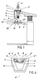
- FIGS. 1 to 4 The device according to the invention which is shown in FIGS. 1 to 4 is designed to be removably mounted on a work plate P which can be seen in FIG. 1.
- the horizontal crosspiece of this device is constituted by a rigid bar 1 which is slightly curved towards the rear of it so as to be able to roughly follow the contour of the forehead of a patient.
- this bar 1 carries, as means for wedging the patient's forehead, fixed support elements 2 ′ and 2 ⁇ which are arranged symmetrically with respect to a vertical plane aa ′ Linked to the device and with which the plane of symmetry of the patient's head must be substantially confused when the latter is correctly wedged.
- each of these elements 2 ′ and 2 ⁇ comprises a disc-shaped or flared cup-shaped part 3 ′, respectively 3 ⁇ , against which one of the sides of the patient's forehead must come lean, and a foot 4 ′, respectively 4 ⁇ , by which this part is fixed to the bar 1.
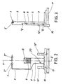
- this bar 1 is carried by one of its ends by the upper part of a single vertical and lateral upright 5 while its other end is free.
- these two elements 1 and 5 are joined end to end but it is obvious that the upright could rise a little higher than the bar and / or that the bar could extend a little beyond beyond the amount.
- the amount is sufficiently far from the plane aa ′ so as not to risk bothering the doctor during an examination or a treatment and that it has a high flexural strength in the direction parallel to this plane.
- aa ′ that is to say that in which the patient exerts a force on the bar 1 when he presses his forehead against the elements 2 ′ and 2 ⁇ .
- the amount 5 can be constituted for example by a bar with rectangular section arranged so that the length of this section is parallel to the plane a-a ′.
- the upright 5 is carried by one end of a horizontal arm 6, the other end is integral with a hollow vertical column 7, which has a plane of symmetry coincident with the plane aa ′ and which is fixed, for example by screws, on a base 10.
- This column 7 which for example has a rectangular or square section, constitutes one of the elements of the support means for those which serve to wedge the patient's chin and which are constituted here by a chin rest 8.
- the other elements of these support means are those of a telescopic system which carries the chin rest 8 and which makes it possible to raise or lower it to adjust the distance between it and the bar 1.
- the base 10 of the device is designed to be able to easily fit into a notch which is situated at the edge of the work plate P which we have spoken of, and which has a shape which corresponds to hers.
- this base is constituted by a part of substantially trapezoidal shape (see FIG. 4) which comprises, except on the side of its large base, a thinned edge 11 intended to come to engage in a groove that the plate presents on its edge , around its also trapezoidal notch.
- the base 10 and the notch of the tray are provided so that, when the base is in place, its large base is aligned with the edge of the tray.
- the device according to the invention can be fixed to the work plate in a manner that is both removable and very stable. Furthermore, when the device is removed from the notch, the latter constitutes a free space in which the head of a patient lying under the work table can be inscribed, in the eyes of which a doctor can intervene, or in which may be placed means for positioning the head of this patient.
- the device also includes two handles 12 ′ and 12 ⁇ which are fixed on the base 10, on either side of the column 7. Thanks to these handles the patient who sits in front of the work table can more easily move his head to wedge it on the device and then keep it still during an exam or procedure.
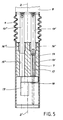
- FIG. 5 schematically shows how the telescopic system which carries the chin rest 8 and which makes it possible to adjust the height of the latter relative to the base 10 is produced.
- This system comprises two vertical cylindrical bars 13 ′ and 13 ⁇ which are located symmetrically with respect to the plane aa ′ and at the upper ends of which the chin rest 8 is fixed, for example by screws, as well as guide means and means of drive to allow these bars to be moved axially in both directions.
- the guide means comprise an elongated metal block 14 of the same section as the internal section of the column 7, which is housed entirely in the upper part of the latter and which is integral therewith.
- This block has in the direction of its length two parallel bores 15 ′ and 15 ⁇ in which the bars 13 ′ and 13 ⁇ are engaged and can penetrate more or less deeply by sliding in two sockets 16 ′ and 16 ⁇ driven into the upper part of these bores.
- the drive means comprise, themselves, an endless screw 17 which is fixed by a tip to the lower end of one, 13 ′, of the vertical bars and situated in the extension thereof, a nut 18 in which passes the screw 17 and which is held in place axially by means not shown, and a reversible electric motor 19 which makes it possible to rotate the nut in both directions, by means of transmission means also not shown, and consequently to raise or lower the screw 17.
- the patient After sitting in front of the work table P, the patient takes the handles 12 ′ and 12 ⁇ in hand, and puts his head forward to press his forehead against the elements 2 ′ and 2 ⁇ . If the chin rest 8 is not at the right height so that the patient can come at the same time to wedge his chin in, the doctor uses the button 20 located at the bottom of column 7, which can be seen in Figures 1 and 2, to operate the motor 19 in one direction or the other and raise or lower the chin guard until it is in the correct position. Then, when the patient has properly wedged his forehead on the support elements and his chin on the chin rest, the doctor can proceed with the examination or intervention he wishes to do.
- the device is designed to allow the lateral upright 5 which carries the horizontal cross member 1 to be placed on the left or right of the patient's face, depending on whether the doctor wishes to have freedom of maneuver. either side of it.
- the device is designed to be able to be used in two symmetrical positions with respect to the vertical plane a-a ′.
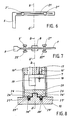
- the horizontal cross member 1 is no longer curved but straight and it no longer carries only two support elements 2 ′ and 2 ⁇ for the front but four, the two additional support elements 22 ′ and 22 ⁇ being obviously placed on the opposite side to that of the elements 2 ′ and 2 ⁇ .
- the device is provided with a system like that of FIG. 8, which makes it possible to rotate the column 7 around a vertical axis contained in the plane aa ′ and to stabilize it in two positions at 180 ° one from the other.
- the column 7 comprises a bottom 23 which has on the outside, a cylindrical central hole 24 in which is engaged a boss of the same shape and the same diameter 25, which comprises the base 10, and two other shaped holes spherical caps 26 ′ and 26 ⁇ which are symmetrical with respect to the axis of the hole 24 and into which two balls 27 ′ and 27 ⁇ can penetrate which emerge more or less from two corresponding cylindrical holes 28 ′ and 28 ⁇ of the base 10, under the thrust of two springs 29 ′ and 29 ⁇ housed in these holes 28′ and 28 ⁇ .
- the depth of the holes 26 ′ and 26 ⁇ and the force that the springs 29 ′ and 29 ⁇ exert on the balls 27′ and 27 ⁇ must be sufficient so that the column 7 does not risk turning under the sole action of the forces that the patient can exercise on the device but only when the doctor wishes.
- the device can comprise either a fixed chin rest 8, which can be used from two sides, or a removable chin rest which can be made to turn around the axis of rotation of the column.
- Such a variant is particularly advantageous because it allows the doctor to have maximum freedom of maneuver on both sides of the patient's face, alternately.
- the lateral upright could be oblique and shaped to pass behind the patient's ear and, independently of this, it could be fixed on the base of the device instead of being carried by the chin rest support means.
- the base of the device could not be a base fixed removably or not on a work platform but the work platform itself.
Landscapes
- Life Sciences & Earth Sciences (AREA)
- Health & Medical Sciences (AREA)
- Medical Informatics (AREA)
- Biophysics (AREA)
- Ophthalmology & Optometry (AREA)
- Engineering & Computer Science (AREA)
- Biomedical Technology (AREA)
- Heart & Thoracic Surgery (AREA)
- Physics & Mathematics (AREA)
- Molecular Biology (AREA)
- Surgery (AREA)
- Animal Behavior & Ethology (AREA)
- General Health & Medical Sciences (AREA)
- Public Health (AREA)
- Veterinary Medicine (AREA)
- Eye Examination Apparatus (AREA)
Applications Claiming Priority (4)
| Application Number | Priority Date | Filing Date | Title |
|---|---|---|---|
| CH374288A CH676421A5 (en) | 1988-10-06 | 1988-10-06 | Ophthalmic head clamp |
| CH3742/88 | 1988-10-06 | ||
| FR8813400 | 1988-10-10 | ||
| FR8813400A FR2638959A1 (fr) | 1988-10-10 | 1988-10-10 | Dispositif pour caler la tete d'un patient notamment pendant un examen ou un traitement ophtalmologique |
Publications (1)
| Publication Number | Publication Date |
|---|---|
| EP0362768A1 true EP0362768A1 (de) | 1990-04-11 |
Family
ID=25693746
Family Applications (1)
| Application Number | Title | Priority Date | Filing Date |
|---|---|---|---|
| EP89118235A Ceased EP0362768A1 (de) | 1988-10-06 | 1989-10-02 | Vorrichtung zur Halterung des Kopfes eines Patienten während der augenärztlichen Untersuchung oder Behandlung |
Country Status (1)
| Country | Link |
|---|---|
| EP (1) | EP0362768A1 (de) |
Cited By (3)
| Publication number | Priority date | Publication date | Assignee | Title |
|---|---|---|---|---|
| WO2000013571A1 (en) * | 1998-09-04 | 2000-03-16 | Sunrise Technologies International, Inc. | Apparatus and method for receiving the head of a subject |
| WO2005112738A3 (en) * | 2004-05-12 | 2006-02-09 | Zeiss Carl Meditec Inc | Motorized patient head support for eye examination or treatment |
| US20170138587A1 (en) * | 2015-11-16 | 2017-05-18 | Ningbo Tianli Lantern Decorations Co., Ltd. | Multi-functional flashlight |
Citations (6)
| Publication number | Priority date | Publication date | Assignee | Title |
|---|---|---|---|---|
| FR1149085A (fr) * | 1956-05-05 | 1957-12-19 | Maison Luer | Ophtalmomètre |
| FR2322576A1 (fr) * | 1975-09-03 | 1977-04-01 | Zeiss Carl Fa | Appui-tete pour examens ophtalmologiques |
| FR2381506A1 (fr) * | 1977-02-28 | 1978-09-22 | Ignatiades Anastasios | Perimetre spherique a enregistrement automatique avec projecteur fixe |
| US4128317A (en) * | 1977-06-01 | 1978-12-05 | Lecover Maurice | Positioning means for ophthalmic examinations |
| EP0038525A1 (de) * | 1980-04-18 | 1981-10-28 | Firma Carl Zeiss | Augenrefraktometer |
| DE8512249U1 (de) * | 1985-04-25 | 1985-06-13 | Fa. Carl Zeiss, 7920 Heidenheim | Instrumententisch für ophthalmologische Geräte |
-
1989
- 1989-10-02 EP EP89118235A patent/EP0362768A1/de not_active Ceased
Patent Citations (6)
| Publication number | Priority date | Publication date | Assignee | Title |
|---|---|---|---|---|
| FR1149085A (fr) * | 1956-05-05 | 1957-12-19 | Maison Luer | Ophtalmomètre |
| FR2322576A1 (fr) * | 1975-09-03 | 1977-04-01 | Zeiss Carl Fa | Appui-tete pour examens ophtalmologiques |
| FR2381506A1 (fr) * | 1977-02-28 | 1978-09-22 | Ignatiades Anastasios | Perimetre spherique a enregistrement automatique avec projecteur fixe |
| US4128317A (en) * | 1977-06-01 | 1978-12-05 | Lecover Maurice | Positioning means for ophthalmic examinations |
| EP0038525A1 (de) * | 1980-04-18 | 1981-10-28 | Firma Carl Zeiss | Augenrefraktometer |
| DE8512249U1 (de) * | 1985-04-25 | 1985-06-13 | Fa. Carl Zeiss, 7920 Heidenheim | Instrumententisch für ophthalmologische Geräte |
Cited By (4)
| Publication number | Priority date | Publication date | Assignee | Title |
|---|---|---|---|---|
| WO2000013571A1 (en) * | 1998-09-04 | 2000-03-16 | Sunrise Technologies International, Inc. | Apparatus and method for receiving the head of a subject |
| WO2005112738A3 (en) * | 2004-05-12 | 2006-02-09 | Zeiss Carl Meditec Inc | Motorized patient head support for eye examination or treatment |
| US7401921B2 (en) | 2004-05-12 | 2008-07-22 | Carl Zeiss Meditec, Inc. | Motorized patient support for eye examination or treatment |
| US20170138587A1 (en) * | 2015-11-16 | 2017-05-18 | Ningbo Tianli Lantern Decorations Co., Ltd. | Multi-functional flashlight |
Similar Documents
| Publication | Publication Date | Title |
|---|---|---|
| FR2893838A1 (fr) | Prothese de disque intervertebral et instrumentation d'insertion de la prothese entre les vertebres | |
| CA2625630C (fr) | Dispositif pour le positionnement angulaire d'un membre d'un patient reposant sur une table d'operation | |
| FR2825808A1 (fr) | Poignee de commande avec repose-main reglable | |
| EP3903756B1 (de) | Orthopädische gehhilfevorrichtung, die zur rehabilitation des gehvermögens verwendet werden kann und mittel zum spreizen der oberschenkel des patienten umfasst | |
| FR2804877A1 (fr) | Fixation de surf | |
| EP0362768A1 (de) | Vorrichtung zur Halterung des Kopfes eines Patienten während der augenärztlichen Untersuchung oder Behandlung | |
| FR2546058A1 (fr) | Appareillage pour le transfert de malades d'un support vers un autre support | |
| CH675543A5 (en) | Safety binding for ski | |
| CH676421A5 (en) | Ophthalmic head clamp | |
| FR2638959A1 (fr) | Dispositif pour caler la tete d'un patient notamment pendant un examen ou un traitement ophtalmologique | |
| FR2841462A1 (fr) | Module de transformation pour fauteuil roulant | |
| CH369545A (fr) | Articulateur dentaire | |
| EP0305250B1 (de) | Tangentialer Ährenheber mit variabler Geometrie | |
| WO2015086967A1 (fr) | Appareil electromenager de preparation culinaire comportant un bras inferieur porte par un socle et un bras superieur relie au bras inferieur par un dispositif d'articulation | |
| EP0216686A1 (de) | Vorrichtung zur Feststellung und Behandlung von Störungen des Binokularsehens | |
| FR2666201A1 (fr) | Chaussure de sport, notamment pour la pratique du ski de fond. | |
| WO2018104595A1 (fr) | Dispositif d'appui antérieur pour les membres inférieurs | |
| EP1321172A1 (de) | Vorrichtung zur Einstellung der Position einer Snowboardbindung | |
| EP3970560B1 (de) | Einrichtung für die ausübung von tischtennis | |
| CA1304973C (fr) | Dispositif pour le depistage et le traitement des troubles de la vision binoculaire | |
| EP4166125B1 (de) | Orthopädische vorrichtung zur unterstützung der entameisenung mit motorisierungsmitteln und mitteln zum spreizen der oberschenkel eines patienten | |
| FR2608057A1 (fr) | Appareil de reeducation pour la recuperation et l'entretien de la mobilite du bassin | |
| WO2004112614A2 (fr) | Coussin de positionnement d'un patient devant subir une ponction lombaire | |
| EP2537501A1 (de) | Verfahren zur Verbesserung eines Krankenbetts mit Installationseinheit | |
| FR3079119A1 (fr) | Dispositif d’aide au passage de la position assise a la position debout, et inversement, plateforme de mobilite pour siege comprenant un tel dispositif, et siege roulant |
Legal Events
| Date | Code | Title | Description |
|---|---|---|---|
| PUAI | Public reference made under article 153(3) epc to a published international application that has entered the european phase |
Free format text: ORIGINAL CODE: 0009012 |
|
| AK | Designated contracting states |
Kind code of ref document: A1 Designated state(s): AT BE DE GB IT LU NL SE |
|
| 17P | Request for examination filed |
Effective date: 19900615 |
|
| 17Q | First examination report despatched |
Effective date: 19921211 |
|
| ITF | It: translation for a ep patent filed | ||
| STAA | Information on the status of an ep patent application or granted ep patent |
Free format text: STATUS: THE APPLICATION HAS BEEN REFUSED |
|
| 18R | Application refused |
Effective date: 19930531 |