EP0362801A2 - Digital control system - Google Patents
Digital control system Download PDFInfo
- Publication number
- EP0362801A2 EP0362801A2 EP89118350A EP89118350A EP0362801A2 EP 0362801 A2 EP0362801 A2 EP 0362801A2 EP 89118350 A EP89118350 A EP 89118350A EP 89118350 A EP89118350 A EP 89118350A EP 0362801 A2 EP0362801 A2 EP 0362801A2
- Authority
- EP
- European Patent Office
- Prior art keywords
- calculation
- positional
- deviation
- velocity
- signal
- Prior art date
- Legal status (The legal status is an assumption and is not a legal conclusion. Google has not performed a legal analysis and makes no representation as to the accuracy of the status listed.)
- Granted
Links
- 238000004364 calculation method Methods 0.000 claims abstract description 294
- 238000000034 method Methods 0.000 claims description 28
- 230000001276 controlling effect Effects 0.000 description 34
- 230000008569 process Effects 0.000 description 25
- 238000005070 sampling Methods 0.000 description 16
- 230000008859 change Effects 0.000 description 10
- 238000010586 diagram Methods 0.000 description 10
- 230000003247 decreasing effect Effects 0.000 description 6
- 230000010354 integration Effects 0.000 description 5
- 230000004075 alteration Effects 0.000 description 3
- 230000007423 decrease Effects 0.000 description 3
- 230000006870 function Effects 0.000 description 3
- 238000012545 processing Methods 0.000 description 3
- 238000012546 transfer Methods 0.000 description 3
- 230000009471 action Effects 0.000 description 2
- 230000005540 biological transmission Effects 0.000 description 2
- 238000002485 combustion reaction Methods 0.000 description 2
- 230000004069 differentiation Effects 0.000 description 2
- 238000011156 evaluation Methods 0.000 description 2
- 230000009467 reduction Effects 0.000 description 2
- 230000004044 response Effects 0.000 description 2
- 238000002474 experimental method Methods 0.000 description 1
- 238000004880 explosion Methods 0.000 description 1
- 239000000446 fuel Substances 0.000 description 1
- 230000007257 malfunction Effects 0.000 description 1
- 238000004886 process control Methods 0.000 description 1
Images




Classifications
-
- G—PHYSICS
- G05—CONTROLLING; REGULATING
- G05B—CONTROL OR REGULATING SYSTEMS IN GENERAL; FUNCTIONAL ELEMENTS OF SUCH SYSTEMS; MONITORING OR TESTING ARRANGEMENTS FOR SUCH SYSTEMS OR ELEMENTS
- G05B1/00—Comparing elements, i.e. elements for effecting comparison directly or indirectly between a desired value and existing or anticipated values
- G05B1/01—Comparing elements, i.e. elements for effecting comparison directly or indirectly between a desired value and existing or anticipated values electric
-
- G—PHYSICS
- G05—CONTROLLING; REGULATING
- G05B—CONTROL OR REGULATING SYSTEMS IN GENERAL; FUNCTIONAL ELEMENTS OF SUCH SYSTEMS; MONITORING OR TESTING ARRANGEMENTS FOR SUCH SYSTEMS OR ELEMENTS
- G05B15/00—Systems controlled by a computer
- G05B15/02—Systems controlled by a computer electric
-
- G—PHYSICS
- G05—CONTROLLING; REGULATING
- G05B—CONTROL OR REGULATING SYSTEMS IN GENERAL; FUNCTIONAL ELEMENTS OF SUCH SYSTEMS; MONITORING OR TESTING ARRANGEMENTS FOR SUCH SYSTEMS OR ELEMENTS
- G05B11/00—Automatic controllers
- G05B11/01—Automatic controllers electric
- G05B11/36—Automatic controllers electric with provision for obtaining particular characteristics, e.g. proportional, integral, differential
- G05B11/42—Automatic controllers electric with provision for obtaining particular characteristics, e.g. proportional, integral, differential for obtaining a characteristic which is both proportional and time-dependent, e.g. P. I., P. I. D.
-
- G—PHYSICS
- G05—CONTROLLING; REGULATING
- G05B—CONTROL OR REGULATING SYSTEMS IN GENERAL; FUNCTIONAL ELEMENTS OF SUCH SYSTEMS; MONITORING OR TESTING ARRANGEMENTS FOR SUCH SYSTEMS OR ELEMENTS
- G05B13/00—Adaptive control systems, i.e. systems automatically adjusting themselves to have a performance which is optimum according to some preassigned criterion
Definitions
- the present invention relates to a digital control system which performs a PID (P: Proportional, I: Integral, D: Derivative) calculation by using positional and velocity algorithms, in accordance with the characteristics of each terms of the PID-calculation.
- PID Proportional Integral
- D Derivative
- Controllers are classified into two categories, i.e., analog PID calculational controllers and digital PID calculational controllers. Until very recently, analog PID calculational controllers have been widely used.
- An analog calculational control system performs a PID calculation by using the following PID basic equation: where MV is the manipulative variable, e is deviation, K p is the proportional gain, T I is the integral action time, T D is the derivative time, and MV0 is the initial value of the manipulative variable.
- Digital calculational control system includes a positional algorithm system and a velocity algorithm system.
- a positional algorithm system performs a PI or PID calculation during each sampling period ⁇ , thereby obtaining an manipulative variable MV n , where n is an integer identifying the sampling period. More specifically, PID calculational equation of the positional algorithm system can be shown by the following equation (2):
- e n , e n-1 , and e n-2 are the deviations produced during the present sampling period, the preceding sampling period, and the sampling period preceding the preceding one, respectively.
- the velocity algorithm system is advantageous over the positional algorithm system in the following respects:
- the positional PID controller shown in Fig. 1 is designed to perform the calculation according to equation (2).
- the controller comprises a detector 1 for detecting a process variable PV n , a deviation calculator 2 for subtracting the value PV n detected by the detector 1, from a set point variable SV n , thereby calculating a deviation e n , and a positional PID calculation device 3 for performing a PID calculation according to equation (2), on the deviation e n , thereby obtaining a manipulative variable MV n .
- the device 3 supplies the value MV n to an object 4, thereby controlling the object 4 such that SV n becomes equal to PV n .
- the velocity-type PID controller illustrated in Fig. 2 is designed to perform calculations according to equations (3a) and (3b).
- the velocity-type PID controller comprises a detector 1 for detecting a process variable PV n , a deviation calculator 2 for subtracting the value PV n by the detector 1, from a set point variable SV n , thereby calculating a deviation e n , and a velocity type PID calculation device 5 for performing a PID calculation according to equation (3a), on the deviation e n , thereby obtaining a change ⁇ MV n in the value MV n , and a velocity-position signal converter 6 for receiving the change ⁇ MV n and performing an calculation according to equation (3b), thus converting the change ⁇ MV n to MV n .
- the converter 6 supplies the value MV n to an object 4, thereby controlling the object 4 such that SV n becomes equal to PV n .
- Upper and lower limits H and L of manipulative variable MV n are set to the velocity
- the positional PID digital controller (Fig. 1) is disadvantageous in some respects. Firstly, it operates but at a low velocity since equation (2) includes a ⁇ -term. Secondly, the bumpless switching is complex, which must be carried out for the manual-automatic mode switching. Thirdly, the controller must perform complex calculations on the signals processed by the other calculating devices.
- the velocity-type PID digital controller (Fig. 2) is also disadvantageous in the following respect. If the set point variable SV n is altered at time n as is shown in Fig. 3, the output value MV n must be controlled as is indicated by the broken-line curve a. If the value SV n is altered at time n, increased over the upper limit H by value c, the output value MV n must be controlled as is indicated by the solid-line curve b, that is, the controller must perform a D calculation to reducing MV n quickly to the upper limit H. This specific control, i.e., an abrupt reduction of MV n to the upper limit H, is difficult to accomplish. Even if it is successfully achieve, it cannot apply to a boiler.
- the velocity-type PID controller is disadvantageous in view of stability and safety.
- the first object of the present invention is to provide a digital controller which performs either a positional PID calculation or a velocity-type PID calculation on PID-calculation, in accordance with the characteristics of the PID-calculation terms.
- the second object of the invention is to provide a digital controller which suppresses a D calculation when a set point variable is altered, thereby to prevent a controlled system from malfunctioning or functioning unstably.
- the third object of the invention is to provide a digital controller which obtains an appropriate I-calculation output when the output process variable increases above an upper limit or decreases below a lower limit, and which prevents a reset wind-up from occurring during the I control of the object.
- the fourth object of the present invention is to provide a method of performing digital calculations in accordance with the characteristics of PID-calculation terms, allowing for a stable and reliable PID control.
- a PI or PID controlling calculation is carried out on the deviation, i.e., the difference between a set point variable and a actual process variable.
- Velocity-type I controlling calculation is performed on the I-calculation term in accordance with the deviation, thereby obtaining an I-controlling calculation output value.
- the velocity-type I-controlling calculation output value is converted to a positional I signal.
- positional P controlling calculation or positional PD controlling calculation are performed on the P-calculation term or the PD-calculation term, respectively, in accordance with the deviation, thereby obtaining a positional P controlling calculation and a positional PD controlling calculation.
- the positional I signal is added to the positional P controlling calculation output or the positional PD controlling calculation output, thus acquiring a manipulative variable.
- the manipulative variable, thus acquired, is supplied to an object, whereby the object is controlled in accordance with the manipulative variable.
- velocity-type I controlling calculation is performed on the I-calculation term in accordance with the deviation, thereby obtaining an I-controlling calculation output value.
- the I-controlling calculation output value is converted to a positional I signal.
- positional P controlling calculation is performed on the P-calculation term, thereby obtaining a positional P controlling calculation, and positional D controlling calculation is carried out on the D-calculation term in accordance with a process variable, thereby obtaining a positional D controlling calculation.
- the positional D controlling calculation eliminates the possibility that problems arise when a D process variable increases above an upper and lower limit due to the alteration of the set point variable.
- the positional I signal, the positional P controlling calculation output, and the positional D controlling calculation output are added, thus providing a to a manipulative variable. This manipulative variable is supplied to an object, whereby the object is controlled in accordance with the manipulative variable.
- PI controlling output is performed on a P-calculation term and an I-calculation term in accordance the deviation, thereby obtaining an I-calculation output
- PID controlling output is performed on a PD-calculation term and an I-calculation term in accordance with the deviation, thereby obtaining an I-calculation output.
- the I-controlling calculation output is converted into a positional I signal by sweep-position signal converting means, and the positional I signal is added to the P-calculation output value obtained from the P-calculation term. The sum of these terms is input to upper/lower limiting means, which produces a manipulative variable.
- the I-calculation output is converted into a positional I signal by velocity-position signal converting means, and the positional I signal is added to the PD-controlling calculation output value obtained from the PD-calculation term.
- the sum of these terms is input to upper/lower limiting means, which produces a manipulative variable.
- upper and lower limits are set to the upper/lower limiting means.
- the limiting means supplies the upper limit, to the velocity-position signal converting means when the input signal is over the upper limit, and supplies the lower limit thereto when the input signal is below the lower limit.
- the limiting means limits the magnitude of a velocity-type I controlling calculation output.
- the digital controller can perform calculations at high velocity to acquire a PID process variable within a short term, a bumpless transfer easily to switch the calculation mode, and calculations on the signals processed by other devices.
- positional controlling calculation is performed on a D-calculation term in accordance with the process variable supplied from an object, not with a deviation i.e., the difference between a set point variable and a actual process variable. Therefore, the D-calculation term is not affected by the alteration of the set point variable. In other words, the D-calculation term causes neither the malfunction nor unstable calculation of the digital controller.
- the I-calculation term is extracted from a PID-calculation term, then converted into a velocity-type I signal by means of velocity-type controlling calculation, and finally processed into a positional I signal by velocity-position signal converting means.
- the PD-calculation term i.e., the remaining part of the PID-calculation term, is subjected to positional adjustment and converted into a positional PD controlling calculation.
- the positional I signal and the positional PD controlling calculation are added.
- the sum of the I signal and the PD controlling calculation output is input to an upper/lower limiting means to which upper and lower limits have been set.
- the velocity-type I controlling calculation output continuously controls the object as long as its magnitude remains between the upper and lower limits set to the signal converting means. Further, no reset wind-up occurs during the I action of the object.
- the P-calculation term is K p ⁇ e
- the I-calculation term is (K p /T1) ⁇ edt
- the D-calculation term is K p ⁇ T D ⁇ (de/dt).
- the P-calculation term is proportional to the present deviation e
- the I-calculation term is proportional to the integrated value of the deviations obtained in the past
- the D-calculation term is proportional to the rate at which the deviation will change in the future.
- Each calculation term performs the control role based on the above equation.
- the I-calculation term is indefinite.
- the D-calculation term is 0 as long as the deviation e remains unchanged.
- each calculation terms properly use the positional algorithm system and the velocity algorithm system, in accordance with the general evaluation shown in Table 1.
- Fig. 4 illustrates a digital controller according to a first embodiment of the present invention.
- the digital controller comprises a set point variable generator 11, an interface 12, a detector 13, an analog-to-digital (A/D) converter 14, an interface 15, a deviation calculator 16, a PI or PID calculation control unit 17, and a digital-to-analog (D/A) converter 18.
- A/D analog-to-digital
- D/A digital-to-analog
- the set point variable generator 11 is designed to generate a set point variable SV. It is a memory of the ordinary type, a program setting device or a digital data generator. If a memory of the ordinary type is used as the generator 11, it reads the set point variable SV at predetermined intervals from the memory. If a program setting device is used as the generator 11, it outputs the set point variable SV every term a predetermined period has elapsed. If a digital data generator is used as the generator 11, it generates the set point variable, either automatically or when manually operated.
- the interface 12 receives the set point variable SV from the generator 11, in response to a sampling signal S supplied from the PI calculation control unit 17, and outputs a presently set point variable SV n .
- the detector 13 continuously detects the analog process variable PV A supplied form an object 19 which is connected to the D/A converter 18 and which the digital controller is to control. Alternatively, the detector 13 detects the analog process variable PV A during each sampling period.
- the A/D converter 14 receives the analog process variable PV A supplied from the detector 13, and converts the value PV A to digital process variable PV.
- the interface 15 has a memory. It receives the digital process variable PV from the A/D converter 14 in response to the sampling signal S supplied from the PI calculation control unit 17. The value PV, thus received, is stored in the memory for some term.
- the digital process variable PV is read from the interface 15 and is input to the deviation calculator 16 as a process variable PV n .
- the deviation calculator 15 receives the output of both interfaces 12 and 15, i.e., SV n and PV n .
- the deviation calculator 15 subtracts the process variable PV n from the set point variable SV n , thereby obtaining a present deviation e n .
- the deviation e n thus obtained, is supplied to the PI calculation control unit 17.
- the PI calculation control unit 17 perform PI calculation on positional algorithm system or velocity algorithm system in accordance with the characteristics of the P-calculation term and the I-calculation term, thereby obtaining a manipulative variable MV n .
- the output value MV n is input to the D/A converter 18.
- the D/A converter 18 converts the output value MV n to an analog output value MV An , which is supplied to the object 19 to control the object 19.
- Fig. 5 illustrates the PI calculation control unit 17 in detail.
- the PI calculation unit 17 is suitable for use in a flow-rate control system or a pressure control system.
- a digital set point variable SV n and a digital process variable PV n are input to the deviation calculator 16 during each sampling period ⁇ .
- the deviation calculator 16 subtracts the present process variable PV n from the present set point variable SV n , thus obtained a present deviation e n made during the sampling period.
- the deviation e n is supplied to the PI calculation control unit 17.
- the unit 17 performs positional PI calculation or velocity-type PI calculation on the present deviation e n , based on the table 1 and in accordance with the characteristics of the P-calculation term and the I-calculation term.
- the PI calculation control unit 17 comprises a positional P-controlling calculation device 21, a velocity-type I-controlling calculation device 22, a velocity-position signal converter 23, and an adder unit 24.
- the positional P-calculation device 21 is designed to perform positional P calculation on the present deviation e n .
- the velocity-type I-Controlling calculation device 22 is designed to perform velocity-type I calculation on the present deviation e n , so as to obtain a velocity-type I calculational signal.
- the signal converter 23 converts the velocity-type I calculational signal into a positional I signal.
- the adder unit 24 is coupled to the object 25. It adds the output MV Pn of the positional P-calculation device 21 to the output MV In of the velocity-position signal converter 23, thereby obtaining a manipulative variable MV n .
- the deviation calculator 16 subtracts the process variable PV n from the present set point variable SV n , thus obtained a present deviation e n made during the sampling period.
- the deviation e n is supplied to the positional P-controlling calculation device 21 and the velocity-type I-controlling calculation device 22.
- the manipulative variable MV n thus obtained, is supplied to the object 15, thereby controlling the object 15 until SV n becomes equal to PV n .
- the P-calculation term and the I-calculation term are subject to a positional algorithm and a velocity algorithm, respectively. Therefore, this digital controller has several advantages.
- no reset wind-up results from the integration terms since it suffices to limit only the change ⁇ MV In obtained for each sampling period. Furthermore, a bumpless transfer can be easily accomplished in switching the calculation mode, from the manual mode to the automatic mode, and vice versa.
- Fig. 6 shows the another digital controller which is a PID calculational system and a second embodiment of the invention.
- the PID calculational system shown in Fig. 6 is designed to generate an manipulative variable MV n suitable for controlling a temperature control system or a level control system.
- the PID calculation unit 17 comprises a positional P-controlling calculation device 21, a velocity-type I-controlling calculation device 22, a signal converter 23, an adder unit 24a, and a positional D-controlling calculation device 26.
- a deviation calculator 16 used also in the second embodiment, and subtracts the process variable PV n from the set point variable SV n , thus obtaining a deviation e n .
- the deviation e n is input to the positional P-controlling calculation device 21, the velocity-type I-controlling calculation device 22, and the positional D-controlling calculation device 26.
- the positional P-controlling calculation device 21 performs the calculation of equation (4) on the deviation e n , thus obtaining a positional P-calculation output value MV Pn .
- the velocity-type I-controlling calculation device 22 performs the calculation of equation (5) on the deviation en, thereby obtaining a velocity-type I-calculation output value ⁇ MV In .
- the value ⁇ MV In is input to the velocity-position signal converter 23.
- the signal converter 23 performs the calculation of equation (6), thus obtaining a positional I-signal MV In .
- the positional D-controlling calculation device 26 performs the following calculation on the deviation e n , thereby obtaining a positional D-output value MV Dn :
- MV Dn K p ⁇ (T D / ⁇ ) ⁇ (e n - e n-1 (8)
- the values output by the controlling calculation devices 21, 23, and 26 are input to the adder unit 24a.
- the manipulative variable MV n is supplied to the object 25, whereby the object 25 is controlled until PV n becomes equal to the set point variable SV n .
- the actual D-calculation term is not exactly differential, that is, (K p ⁇ T D ⁇ s)/ ⁇ (1 + ⁇ T D ⁇ s), where T D is derivative time, (1/ ⁇ ) is differential gain, ⁇ is 0.1 to 0.3 in most cases, and s is Laplace operator. Therefore, when the positional D-controlling calculation device 26 performs inexact differentiation, its output ⁇ MV Dn will be:
- the digital controller attains the same advantages as the digital controller having the PI calculation unit shown in Fig. 5.
- an over-range P-controlling calculation output and an over-range D-controlling calculation output, if any, are not decreased out.
- the digital controller i.e., the second embodiment of the invention, performs a safe an reliable PID control.
- Fig. 7 illustrates another PID calculational system which can be used in the second embodiment, in place of the PID calculational system shown in Fig. 6.
- the PID calculational system shown in Fig. 7 is identical to the PID calculational system shown in Fig. 6, except that positional D-controlling calculation device 26a performs positional D-calculation on the process variable PV n , not on the deviation e n as in the calculational system illustrated in Figs. 5 and 6.
- the D-calculation output changes if the set point variable SV n and the process variable PV n change. Therefore, the derivative term is adjusted in order to achieve a reliable process control.
- the deviation e n changes greatly as the set point variable SV n is altered, the differentiation will be performed to an excessive degree, inevitably causing an over-shooting of the manipulation calculation output.
- the changes in the set point variable SV n is ignored, and positional D-calculation is performed on the process variable PV n . Therefore, no over-shooting of the manipulative variable will occur, and the digital controller having the PID calculation unit shown in Fig. 7 accomplishes a safe and reliable PID control.
- Fig. 8 shows another PI calculational system which can be used in the second embodiment of the invention, in place of the PID calculational system illustrated in Fig. 6.
- the PI calculational system shown in Fig. 8 is designed to limit not only the manipulative variable MV n but also the I-calculation output, when necessary in accordance with the various conditions of an object 25.
- this PI calculational system comprises a positional P-controlling calculation device 21, a velocity-type I-controlling calculation device 22, a velocity-position signal converter 31, an adder unit 32, and an upper/lower limiter 33.
- the signal converter 31 performs two functions: (i) to converts the output of the velocity-type I-controlling calculation device 22 to a positional I-signal, and (ii) to limit the output of the positional I-signal in accordance with the upper limit H and the lower limit L set to it by the upper/lower limiter 33.
- the adder unit 32 is used to add the outputs of the controlling calculation devices 21 and 31, so as to obtain an manipulative variable MV n .
- the upper limit H and the lower limit L have been externally set to the upper/lower limiter 33.
- the limiter 32 reduces the manipulative variable MV n output from the adder unit 32 to the upper limit H when the value MV n is over the upper limit H, and maintain the value MV n at the lower limit L when the value MV n is less than the lower limit L.
- the deviation calculator 16 subtracts the process variable PV n from the set point variable SV n , thus obtaining a deviation en.
- the deviation e n is input to the positional P-controlling calculation device 21 and the velocity-type I-controlling calculation device 22.
- the positional P-controlling calculation device 21 performs the calculation of equation (4) on the deviation en, thus obtaining a positional P-calculation output value MV Pn .
- the value MV Pn is input to the adder unit 32.
- the velocity-type I-controlling calculation device 22 performs the calculation of equation (5) on the deviation en, thereby obtaining a velocity-type I-calculation output value ⁇ MV In .
- the value ⁇ MV In is input to the signal converter 31.
- the signal converter 31 converts the value ⁇ MV In , without limiting the same, to a positional I-signal.
- the I-signal is input to the adder unit 32.
- the adder unit 32 adds the value MV Pn and the value MV In , thus obtaining an manipulative variable MV n .
- the manipulative variable MV n is input to the upper/lower limiter 33.
- the upper/lower limiter 33 reduces the manipulative variable MV n to the upper limit H when the value MV n is greater than the upper limit H, and maintain the output value MV n at the lower limit L when the value MV n is less than the lower limit L.
- the manipulative variable MV n thus processed, is supplied to the object 25.
- the manipulative variable MV n gradually increases along with the I-signal MV In , eventually causing a reset wind-up.
- the integration can be stopped when the manipulative variable MV n maintain to the upper limit H or decreases to the lower limit L.
- the value MV n maintain over the upper limit H or maintain below the lower limit L, in most cases, due to the changes in the proportional component or differential component of the value MV n which appear before the integral component. It follows that the integral output value, which has yet to change, still remains when the manipulative variable MV n reaches the upper limit H or the lower limit L. Consequently, the integral component of the value MV n will be discarded.
- the digital controller having the PI calculational system shown in Fig. 8 is advantageous, in the following respects, over a digital controller wherein the integration is stopped the moment the manipulative variable MV n reaches the upper limit H or the lower limit L.
- the controller can control the object, exactly in accordance with the changes in the condition of the object, since the I-signal MV In has an appropriate value due to the continuous integration even if the manipulative variable MV n decreases below the upper limit H after it has reached the upper limit H, or maintain above the lower limit L after it has reached the lower limit L.
- Fig. 9 also illustrates a PID calculational system which can be used in the second embodiment of the invention, in place of the PID calculational unit shown in Fig. 6.
- the PID calculational system shown in Fig. 9 is identical to the unit shown in Fig. 8, except that a positional D-calculation controlling device 26 is used.
- the unit operates in the same way as the PID calculational system shown in Fig. 8, so as to attain the same advantages.
- Fig. 10 is a schematic representation of another PID calculational system which can be used in the second embodiment of the invention, in place of the PID calculational system shown in Fig. 6. Like the PID calculational system shown in Figs. 6, 7, 8, and 9, this unit performs either a positional or a velocity-type on a P-calculation term, an I-calculation term, and a D-calculation term, in accordance with the characteristics of these calculation terms. As can be understood from Fig. 10, this PID calculational system is different from those illustrated in Figs. 6, 7, 8, and 9, in that a set point variable filter 41 is connected between an interface 12 (Fig. 4) and a deviation calculator 16.
- the PID calculation unit shown in Fig. 10 is designed to add a control constant to a P-calculation term and an I-calculation term, thereby to control the influence of external disturbance on the manipulative variable MV n . More specifically, the parameter of the set point variable filter 41 is switched between two values in accordance with the magnitude of the external disturbance, thereby to change the control constant only, so that the object 25 is controlled most appropriately.
- the control system illustrated in Fig. 10 can be represented by the transmission functions shown in Fig. 11.
- the influence of the alteration of the set point variable SV n on the P-calculation term is given by:
- the control constant K p of the P-calculation term changes between two values when the parameter ⁇ of the set point variable filter 41 is switched between two values in accordance with the magnitude of the external disturbance. Therefore, the digital controller having the PID calculational system shown in Fig. 10 performs an optimal control of the object 25 even when the set point variable SV n is altered.
Landscapes
- Engineering & Computer Science (AREA)
- Physics & Mathematics (AREA)
- General Physics & Mathematics (AREA)
- Automation & Control Theory (AREA)
- General Engineering & Computer Science (AREA)
- Health & Medical Sciences (AREA)
- Artificial Intelligence (AREA)
- Computer Vision & Pattern Recognition (AREA)
- Evolutionary Computation (AREA)
- Medical Informatics (AREA)
- Software Systems (AREA)
- Feedback Control In General (AREA)
Abstract
Description
- The present invention relates to a digital control system which performs a PID (P: Proportional, I: Integral, D: Derivative) calculation by using positional and velocity algorithms, in accordance with the characteristics of each terms of the PID-calculation.
- Controllers are classified into two categories, i.e., analog PID calculational controllers and digital PID calculational controllers. Until very recently, analog PID calculational controllers have been widely used.
- An analog calculational control system performs a PID calculation by using the following PID basic equation:

- Recently, digital calculational control system have come into use in increasing numbers, due to the spread use of electronic computers and the accomplishment of high-velocity processing of signals. Digital calculational control system includes a positional algorithm system and a velocity algorithm system.
- A positional algorithm system performs a PI or PID calculation during each sampling period τ, thereby obtaining an manipulative variable MVn, where n is an integer identifying the sampling period. More specifically, PID calculational equation of the positional algorithm system can be shown by the following equation (2):

- A velocity algorithm system finds a change ΔMVn in the MV, which occurs during each sampling period, and adds this change ΔMVn to the output MVn-1 acquired in the preceding sampling period, thereby obtaining the output MVn for the sampling period. More specifically, PID calculational equation of the velocity algorithm system can be represented by the following equations (3a) and (3b):

- The equation (2), (3a) and (3b) are obtained from the basic equation (1).
- In equations (2) and (3a), en, en-1, and en-2 are the deviations produced during the present sampling period, the preceding sampling period, and the sampling period preceding the preceding one, respectively. As can be understood from equation (2) with equations (3a) and (3b), the velocity algorithm system is advantageous over the positional algorithm system in the following respects:
- (1) The calculation which the velocity algorithm system performs is easy since equations (3a) and (3b) have no Σ-terms.
- (2) In the case of a velocity algorithm system which can be manually or automatically operated, it suffices to control an object in accordance with MVn-1 after the manual calculation has been switched to the automatic calculation and to add ΔMVn to ΔMVn⁻¹. The output obtained during the preceding sampling period, i.e., MVn-1, need not be adjusted to allow for the switching of the calculation mode. Hence, the calculation mode can be easily and smoothly changed from the manual one to the automatic one.
- (3) The velocity algorithm system can accomplish a precise PID control, only if ΔMVn is limited, or the gain thereof is adjusted. The system is, therefore, compatible with other arithmetic calculation devices. In other words, it can easily perform calculations on not only the signals generated in it self, but also the signals processed by the other calculation devices.
- For the advantages described above, most direct digital control (DDC) system in practical use is of the velocity-type.
- Two conventional digital controllers, which are a positional and a velocity-type, will be described in more detail with reference to Fig. 1 and Fig. 2, respectively.
- The positional PID controller shown in Fig. 1 is designed to perform the calculation according to equation (2). As Fig. 1 shows, the controller comprises a
detector 1 for detecting a process variable PVn, adeviation calculator 2 for subtracting the value PVn detected by thedetector 1, from a set point variable SVn, thereby calculating a deviation en, and a positionalPID calculation device 3 for performing a PID calculation according to equation (2), on the deviation en, thereby obtaining a manipulative variable MVn. Thedevice 3 supplies the value MVn to anobject 4, thereby controlling theobject 4 such that SVn becomes equal to PVn. - The velocity-type PID controller illustrated in Fig. 2 is designed to perform calculations according to equations (3a) and (3b). As Fig. 2 shows, the velocity-type PID controller comprises a
detector 1 for detecting a process variable PVn, adeviation calculator 2 for subtracting the value PVn by thedetector 1, from a set point variable SVn, thereby calculating a deviation en, and a velocity typePID calculation device 5 for performing a PID calculation according to equation (3a), on the deviation en, thereby obtaining a change ΔMVn in the value MVn, and a velocity-position signal converter 6 for receiving the change ΔMVn and performing an calculation according to equation (3b), thus converting the change ΔMVn to MVn. Theconverter 6 supplies the value MVn to anobject 4, thereby controlling theobject 4 such that SVn becomes equal to PVn. Upper and lower limits H and L of manipulative variable MVn are set to the velocity-position signal converter 6. - The positional PID digital controller (Fig. 1) is disadvantageous in some respects. Firstly, it operates but at a low velocity since equation (2) includes a Σ-term. Secondly, the bumpless switching is complex, which must be carried out for the manual-automatic mode switching. Thirdly, the controller must perform complex calculations on the signals processed by the other calculating devices.
- The velocity-type PID digital controller (Fig. 2) is also disadvantageous in the following respect. If the set point variable SVn is altered at time n as is shown in Fig. 3, the output value MVn must be controlled as is indicated by the broken-line curve a. If the value SVn is altered at time n, increased over the upper limit H by value c, the output value MVn must be controlled as is indicated by the solid-line curve b, that is, the controller must perform a D calculation to reducing MVn quickly to the upper limit H. This specific control, i.e., an abrupt reduction of MVn to the upper limit H, is difficult to accomplish. Even if it is successfully achieve, it cannot apply to a boiler. Should it be used in controlling a boiler, the opening of a valve supplying air or fuel into a combustion chamber would be reduced too much, increasing the possibility of incomplete combustion and, ultimately, an explosion. The velocity-type PID controller is disadvantageous in view of stability and safety.
- The first object of the present invention is to provide a digital controller which performs either a positional PID calculation or a velocity-type PID calculation on PID-calculation, in accordance with the characteristics of the PID-calculation terms.
- The second object of the invention is to provide a digital controller which suppresses a D calculation when a set point variable is altered, thereby to prevent a controlled system from malfunctioning or functioning unstably.
- The third object of the invention is to provide a digital controller which obtains an appropriate I-calculation output when the output process variable increases above an upper limit or decreases below a lower limit, and which prevents a reset wind-up from occurring during the I control of the object.
- The fourth object of the present invention is to provide a method of performing digital calculations in accordance with the characteristics of PID-calculation terms, allowing for a stable and reliable PID control.
- According to one aspect of the invention, a PI or PID controlling calculation is carried out on the deviation, i.e., the difference between a set point variable and a actual process variable. Velocity-type I controlling calculation is performed on the I-calculation term in accordance with the deviation, thereby obtaining an I-controlling calculation output value. The velocity-type I-controlling calculation output value is converted to a positional I signal. Meanwhile, positional P controlling calculation or positional PD controlling calculation are performed on the P-calculation term or the PD-calculation term, respectively, in accordance with the deviation, thereby obtaining a positional P controlling calculation and a positional PD controlling calculation. The positional I signal is added to the positional P controlling calculation output or the positional PD controlling calculation output, thus acquiring a manipulative variable. The manipulative variable, thus acquired, is supplied to an object, whereby the object is controlled in accordance with the manipulative variable.
- Alternatively, velocity-type I controlling calculation is performed on the I-calculation term in accordance with the deviation, thereby obtaining an I-controlling calculation output value. The I-controlling calculation output value is converted to a positional I signal. Meanwhile, positional P controlling calculation is performed on the P-calculation term, thereby obtaining a positional P controlling calculation, and positional D controlling calculation is carried out on the D-calculation term in accordance with a process variable, thereby obtaining a positional D controlling calculation. The positional D controlling calculation eliminates the possibility that problems arise when a D process variable increases above an upper and lower limit due to the alteration of the set point variable. The positional I signal, the positional P controlling calculation output, and the positional D controlling calculation output are added, thus providing a to a manipulative variable. This manipulative variable is supplied to an object, whereby the object is controlled in accordance with the manipulative variable.
- Alternatively, PI controlling output is performed on a P-calculation term and an I-calculation term in accordance the deviation, thereby obtaining an I-calculation output, or PID controlling output is performed on a PD-calculation term and an I-calculation term in accordance with the deviation, thereby obtaining an I-calculation output. In the first case, the I-controlling calculation output is converted into a positional I signal by sweep-position signal converting means, and the positional I signal is added to the P-calculation output value obtained from the P-calculation term. The sum of these terms is input to upper/lower limiting means, which produces a manipulative variable. In the second case, the I-calculation output is converted into a positional I signal by velocity-position signal converting means, and the positional I signal is added to the PD-controlling calculation output value obtained from the PD-calculation term. The sum of these terms is input to upper/lower limiting means, which produces a manipulative variable. In either case, upper and lower limits are set to the upper/lower limiting means. The limiting means supplies the upper limit, to the velocity-position signal converting means when the input signal is over the upper limit, and supplies the lower limit thereto when the input signal is below the lower limit. In other words, the limiting means limits the magnitude of a velocity-type I controlling calculation output.
- Hence, when the I-calculation term is extracted from the PI-calculation term or the PID-calculation term, and the velocity-type controlling calculation is performed on the I-calculation term, the I-calculation term will have no Σ-calculation terms. As a result of this, the digital controller according to the invention can perform calculations at high velocity to acquire a PID process variable within a short term, a bumpless transfer easily to switch the calculation mode, and calculations on the signals processed by other devices.
- According to another aspect of the invention, positional controlling calculation is performed on a D-calculation term in accordance with the process variable supplied from an object, not with a deviation i.e., the difference between a set point variable and a actual process variable. Therefore, the D-calculation term is not affected by the alteration of the set point variable. In other words, the D-calculation term causes neither the malfunction nor unstable calculation of the digital controller.
- According to still another aspect of the invention, the I-calculation term is extracted from a PID-calculation term, then converted into a velocity-type I signal by means of velocity-type controlling calculation, and finally processed into a positional I signal by velocity-position signal converting means. Meanwhile, the PD-calculation term, i.e., the remaining part of the PID-calculation term, is subjected to positional adjustment and converted into a positional PD controlling calculation. The positional I signal and the positional PD controlling calculation are added. The sum of the I signal and the PD controlling calculation output is input to an upper/lower limiting means to which upper and lower limits have been set. When the sum is over the upper limit, the upper limit is set to the signal converting means. When the sum is below the lower limit, the lower limit is set to the signal converting means. Hence, the velocity-type I controlling calculation output continuously controls the object as long as its magnitude remains between the upper and lower limits set to the signal converting means. Further, no reset wind-up occurs during the I action of the object.
- This invention can be more fully understood from the following detailed description when taken in conjunction with the accompanying drawings, in which:
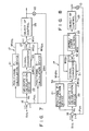
- Fig. 1 a block diagram showing a prior-art, positional PID digital controller;
- Fig. 2 is also a block diagram illustrating a conventional, velocity-type PID digital controller;
- Fig. 3 is a graph representing how the manipulative variable by the controller shown in Fig. 2 changes with respect to a set point variable;
- Fig. 4 is a block diagram illustrating a digital controller according to a first embodiment of the present invention;
- Fig. 5 is a block diagram showing a PI calculation unit incorporated in the first embodiment;
- Fig. 6 is a block diagram showing the PID calculation unit incorporated in another digital controller according to a second embodiment of the present invention;
- Fig. 7 is a block diagram illustrating a PID calculation unit which can be used in the second embodiment, in place of the PID calculation unit shown in Fig. 6;
- Fig. 8 is a block diagram showing another PID calculation unit which can be incorporated in the second embodiment, in place of the PID calculation unit shown in Fig. 6, and also explaining how signals are controlled in the PID calculation unit;
- Fig. 9 is a block diagram showing still another PID calculation unit which can be incorporated in the second embodiment, in place of the PID calculation unit shown in Fig. 6, and also explaining how signals are controlled in the PID calculation unit;
- Fig. 10 is a block diagram showing another PID calculation unit which can be incorporated in the second embodiment, in place of the PID calculation unit shown in Fig. 6, and also illustrating a set point variable filter used in combination with the PID calculation unit; and
- Fig. 11 is a diagram showing the components of the PID calculation unit and the set point variable filter, in terms of transmission functions.
- Before the embodiments of the present invention are described, the principle of PID control, and the rules of processing signals involved in the PID control, will be explained.
- From equation (3), the P-calculation term is Kp·e, the I-calculation term is (Kp/T₁)∫edt, and the D-calculation term is Kp·TD·(de/dt). Obviously, the P-calculation term is proportional to the present deviation e, the I-calculation term is proportional to the integrated value of the deviations obtained in the past, and the D-calculation term is proportional to the rate at which the deviation will change in the future. Each calculation term performs the control role based on the above equation. The I-calculation term is indefinite. The P-calculation term is 0 when e = 0. The D-calculation term is 0 as long as the deviation e remains unchanged. P and D-calculation term are zero standards. As a result, there is following restriction for signal processing. Velocity-type signals can be ignored in calculating the I-calculation term. By contrast, velocity-type signals cannot be ignored in calculating the D-calculation term and the P-calculation term. This is because, if the velocity-type signals are discarded, the P-calculation term and the D-calculation term cannot be 0 when the deviation is 0 or remains unchanged.
- The inventors hereof has repeated experiments, wherein signals involved in the PID control were processed in various ways, and they studied the characteristics of the P-calculation term, the I-calculation term, and the D-calculation term. The results of their study were as is shown in the following table.
Table 1 No. Term Position Velocity T. Remarks P I D P I D 1 Only P control possible? Y N Velocity-type are indefinite 2 P-calculation range decreased Y N Decreased only overrange for the velocity type 3 I calculation easy? N Y Very easy for the velocity type 4 Reset wind-up prevented in I calculation? N Y 5 D-calcualtion overragne decreased Y N Decreased only overrange for the velocity type 6 Bumpless transfer easy in manual-auto switching? N Y For the velocity type, MVn-1 is present manipulative variable 7 Complex calcualtion easy to perform? N Y Only changes are limited or gain-adjusted for the velocity type General Evaluation Y N Y N Y N Note: Y = Yes, N = No. - As is evident from Table 1, the characteristics of the P-calculation term, the I-calculation term, and the D-calculation term are different for the positional algorithm system and the velocity-control algorithm system. According to the present invention, each calculation terms properly use the positional algorithm system and the velocity algorithm system, in accordance with the general evaluation shown in Table 1.
- The digital controllers according to the present inventions will now be described with reference to the accompanying drawings.
- Fig. 4 illustrates a digital controller according to a first embodiment of the present invention. As this figure shows, the digital controller comprises a set point variable generator 11, an
interface 12, adetector 13, an analog-to-digital (A/D)converter 14, aninterface 15, adeviation calculator 16, a PI or PIDcalculation control unit 17, and a digital-to-analog (D/A)converter 18. - The set point variable generator 11 is designed to generate a set point variable SV. It is a memory of the ordinary type, a program setting device or a digital data generator. If a memory of the ordinary type is used as the generator 11, it reads the set point variable SV at predetermined intervals from the memory. If a program setting device is used as the generator 11, it outputs the set point variable SV every term a predetermined period has elapsed. If a digital data generator is used as the generator 11, it generates the set point variable, either automatically or when manually operated. The
interface 12 receives the set point variable SV from the generator 11, in response to a sampling signal S supplied from the PIcalculation control unit 17, and outputs a presently set point variable SVn. Thedetector 13 continuously detects the analog process variable PVA supplied form anobject 19 which is connected to the D/A converter 18 and which the digital controller is to control. Alternatively, thedetector 13 detects the analog process variable PVA during each sampling period. The A/D converter 14 receives the analog process variable PVA supplied from thedetector 13, and converts the value PVA to digital process variable PV. Theinterface 15 has a memory. It receives the digital process variable PV from the A/D converter 14 in response to the sampling signal S supplied from the PIcalculation control unit 17. The value PV, thus received, is stored in the memory for some term. The digital process variable PV is read from theinterface 15 and is input to thedeviation calculator 16 as a process variable PVn. - The
deviation calculator 15 receives the output of bothinterfaces deviation calculator 15 subtracts the process variable PVn from the set point variable SVn, thereby obtaining a present deviation en. The deviation en, thus obtained, is supplied to the PIcalculation control unit 17. The PIcalculation control unit 17 perform PI calculation on positional algorithm system or velocity algorithm system in accordance with the characteristics of the P-calculation term and the I-calculation term, thereby obtaining a manipulative variable MVn. The output value MVn is input to the D/A converter 18. The D/A converter 18 converts the output value MVn to an analog output value MVAn, which is supplied to theobject 19 to control theobject 19. - Fig. 5 illustrates the PI
calculation control unit 17 in detail. ThePI calculation unit 17 is suitable for use in a flow-rate control system or a pressure control system. For the sake of simplicity, it is assumed that a digital set point variable SVn and a digital process variable PVn are input to thedeviation calculator 16 during each sampling period τ. Thedeviation calculator 16 subtracts the present process variable PVn from the present set point variable SVn, thus obtained a present deviation en made during the sampling period. The deviation en is supplied to the PIcalculation control unit 17. Theunit 17 performs positional PI calculation or velocity-type PI calculation on the present deviation en, based on the table 1 and in accordance with the characteristics of the P-calculation term and the I-calculation term. - As is shown in Fig. 5, the PI
calculation control unit 17 comprises a positional P-controllingcalculation device 21, a velocity-type I-controllingcalculation device 22, a velocity-position signal converter 23, and anadder unit 24. The positional P-calculation device 21 is designed to perform positional P calculation on the present deviation en. The velocity-type I-Controlling calculation device 22 is designed to perform velocity-type I calculation on the present deviation en, so as to obtain a velocity-type I calculational signal. Thesignal converter 23 converts the velocity-type I calculational signal into a positional I signal. Theadder unit 24 is coupled to theobject 25. It adds the output MVPn of the positional P-calculation device 21 to the output MVIn of the velocity-position signal converter 23, thereby obtaining a manipulative variable MVn. - The operation of the digital controller shown in Figs. 4 and 5 will now be explained. First, the
deviation calculator 16 subtracts the process variable PVn from the present set point variable SVn, thus obtained a present deviation en made during the sampling period. The deviation en is supplied to the positional P-controllingcalculation device 21 and the velocity-type I-controllingcalculation device 22. The P-controllingcalculation device 21 performs the following calculation, thus obtaining a positional P output MVPn:
MVPn = Kp·en (4)
Meanwhile, the velocity-type I-controllingcalculation device 22 performs the following calculation, thereby obtaining a velocity-type I output ΔMVIn:
ΔMVIn = Kp·(τ/T1) en (5)
The velocity-type I output ΔMVIn is input to the velocity-position signal converter 23. Thesignal converter 23 performs the following calculation, thus obtaining a positional I output MVIn:
MVIn = MVIn-1 + ΔMVIn (6)
The positional P output MVPn and the positional I output MVIn are input to theadder unit 24. Theadder unit 24 carries out the following calculation, obtaining a manipulative variable MVn:
MVn = MVPn + MVIn (7)
The manipulative variable MVn, thus obtained, is supplied to theobject 15, thereby controlling theobject 15 until SVn becomes equal to PVn. - As has been described, in the digital controller shown in Figs. 4 and 5, the P-calculation term and the I-calculation term are subject to a positional algorithm and a velocity algorithm, respectively. Therefore, this digital controller has several advantages. First, when the deviation en varies step by step and P calculation output is over-ranged, an over-range P-calculation output, if any, is not decreased at all. Therefore, control disturbance is low and the PI control is greatly reliable. Second, the I calculation is easy and can be effected at high velocity since the I-calculation term is extracted from the PI-calculation term and the subjected to the velocity-type calculation. Third, no reset wind-up results from the integration terms since it suffices to limit only the change ΔMVIn obtained for each sampling period. Furthermore, a bumpless transfer can be easily accomplished in switching the calculation mode, from the manual mode to the automatic mode, and vice versa.
- Fig. 6 shows the another digital controller which is a PID calculational system and a second embodiment of the invention. The PID calculational system shown in Fig. 6 is designed to generate an manipulative variable MVn suitable for controlling a temperature control system or a level control system. As is evident from Fig. 6, the
PID calculation unit 17 comprises a positional P-controllingcalculation device 21, a velocity-type I-controllingcalculation device 22, asignal converter 23, anadder unit 24a, and a positional D-controllingcalculation device 26. - The operation of the second embodiment will now be explained. A
deviation calculator 16 used also in the second embodiment, and subtracts the process variable PVn from the set point variable SVn, thus obtaining a deviation en. The deviation en is input to the positional P-controllingcalculation device 21, the velocity-type I-controllingcalculation device 22, and the positional D-controllingcalculation device 26. The positional P-controllingcalculation device 21 performs the calculation of equation (4) on the deviation en, thus obtaining a positional P-calculation output value MVPn. The velocity-type I-controllingcalculation device 22 performs the calculation of equation (5) on the deviation en, thereby obtaining a velocity-type I-calculation output value ΔMVIn. The value ΔMVIn is input to the velocity-position signal converter 23. Thesignal converter 23 performs the calculation of equation (6), thus obtaining a positional I-signal MVIn. - In the meanterm, the positional D-controlling
calculation device 26 performs the following calculation on the deviation en, thereby obtaining a positional D-output value MVDn:
MVDn = Kp·(TD/τ)·(en - en-1 (8) - The values output by the controlling
calculation devices adder unit 24a. Theadder unit 24a performs the following calculation on these input value obtaining a manipulative variable MVn:
MVn = MVPn + MVIn + MVDn (9) - The manipulative variable MVn, thus obtained, is supplied to the
object 25, whereby theobject 25 is controlled until PVn becomes equal to the set point variable SVn. - In theory, the D-calculation term used in the second embodiment is exactly differential, i.e., Kp·(TD/τ) = Kp·s. In most cases, however, the actual D-calculation term is not exactly differential, that is, (Kp·TD·s)/·(1 + η·TD·s), where TD is derivative time, (1/η) is differential gain, η is 0.1 to 0.3 in most cases, and s is Laplace operator. Therefore, when the positional D-controlling
calculation device 26 performs inexact differentiation, its output ΔMVDn will be:
- Hence, the digital controller attains the same advantages as the digital controller having the PI calculation unit shown in Fig. 5. In addition, an over-range P-controlling calculation output and an over-range D-controlling calculation output, if any, are not decreased out. The digital controller, i.e., the second embodiment of the invention, performs a safe an reliable PID control.
- Fig. 7 illustrates another PID calculational system which can be used in the second embodiment, in place of the PID calculational system shown in Fig. 6. The PID calculational system shown in Fig. 7 is identical to the PID calculational system shown in Fig. 6, except that positional D-controlling
calculation device 26a performs positional D-calculation on the process variable PVn, not on the deviation en as in the calculational system illustrated in Figs. 5 and 6. - Generally, when D-calculation is performed on the deviation en, the D-calculation output changes if the set point variable SVn and the process variable PVn change. Therefore, the derivative term is adjusted in order to achieve a reliable process control. However, when the deviation en changes greatly as the set point variable SVn is altered, the differentiation will be performed to an excessive degree, inevitably causing an over-shooting of the manipulation calculation output.
- According to the present invention, the changes in the set point variable SVn is ignored, and positional D-calculation is performed on the process variable PVn. Therefore, no over-shooting of the manipulative variable will occur, and the digital controller having the PID calculation unit shown in Fig. 7 accomplishes a safe and reliable PID control.
- Fig. 8 shows another PI calculational system which can be used in the second embodiment of the invention, in place of the PID calculational system illustrated in Fig. 6. The PI calculational system shown in Fig. 8 is designed to limit not only the manipulative variable MVn but also the I-calculation output, when necessary in accordance with the various conditions of an
object 25. As is illustrated in Fig. 8, this PI calculational system comprises a positional P-controllingcalculation device 21, a velocity-type I-controllingcalculation device 22, a velocity-position signal converter 31, anadder unit 32, and an upper/lower limiter 33. Thesignal converter 31 performs two functions: (i) to converts the output of the velocity-type I-controllingcalculation device 22 to a positional I-signal, and (ii) to limit the output of the positional I-signal in accordance with the upper limit H and the lower limit L set to it by the upper/lower limiter 33. Theadder unit 32 is used to add the outputs of the controllingcalculation devices lower limiter 33. Thelimiter 32 reduces the manipulative variable MVn output from theadder unit 32 to the upper limit H when the value MVn is over the upper limit H, and maintain the value MVn at the lower limit L when the value MVn is less than the lower limit L. - The operation of the PI control unit shown in Fig. 8 will now be explained. The
deviation calculator 16 subtracts the process variable PVn from the set point variable SVn, thus obtaining a deviation en. The deviation en is input to the positional P-controllingcalculation device 21 and the velocity-type I-controllingcalculation device 22. The positional P-controllingcalculation device 21 performs the calculation of equation (4) on the deviation en, thus obtaining a positional P-calculation output value MVPn. The value MVPn is input to theadder unit 32. The velocity-type I-controllingcalculation device 22 performs the calculation of equation (5) on the deviation en, thereby obtaining a velocity-type I-calculation output value ΔMVIn. The value ΔMVIn is input to thesignal converter 31. Thesignal converter 31 converts the value ΔMVIn, without limiting the same, to a positional I-signal. The I-signal is input to theadder unit 32. - The
adder unit 32 adds the value MVPn and the value MVIn, thus obtaining an manipulative variable MVn. The manipulative variable MVn is input to the upper/lower limiter 33. The upper/lower limiter 33 reduces the manipulative variable MVn to the upper limit H when the value MVn is greater than the upper limit H, and maintain the output value MVn at the lower limit L when the value MVn is less than the lower limit L. The manipulative variable MVn, thus processed, is supplied to theobject 25. - Unless the value ΔMVIn is limited when the manipulative variable MVn is greater than the upper limit H or less than the lower limit L, the manipulative variable MVn gradually increases along with the I-signal MVIn, eventually causing a reset wind-up. To prevent a reset wind-up, the integration can be stopped when the manipulative variable MVn maintain to the upper limit H or decreases to the lower limit L. In this regard, the value MVn maintain over the upper limit H or maintain below the lower limit L, in most cases, due to the changes in the proportional component or differential component of the value MVn which appear before the integral component. It follows that the integral output value, which has yet to change, still remains when the manipulative variable MVn reaches the upper limit H or the lower limit L. Consequently, the integral component of the value MVn will be discarded.
- In the PI calculational system shown in Fig. 8, when the manipulative variable MVn reaches the upper limit H set to the upper/
lower limiter 33 or the lower limit thereof, the upper limit H or the lower limit L is set to thesignal converter 31. Then, the integration is performed until the I-signal MVIn output by thesignal converter 31 reaches the upper limit H or the lower limit L, thereby preventing a reset wind-up. - Therefore, the digital controller having the PI calculational system shown in Fig. 8 is advantageous, in the following respects, over a digital controller wherein the integration is stopped the moment the manipulative variable MVn reaches the upper limit H or the lower limit L. First, the controller can control the object, exactly in accordance with the changes in the condition of the object, since the I-signal MVIn has an appropriate value due to the continuous integration even if the manipulative variable MVn decreases below the upper limit H after it has reached the upper limit H, or maintain above the lower limit L after it has reached the lower limit L. Second, that portion of the I-signal MVIn which is maintain is reduced when a velocity-type signal SA is added to the I-signal during a feed-forward control, since the
signal converter 32 is set to the upper limit H when the output value MVn maintain to the upper limit H, or the lower limit L is set to theconverter 31 when the manipulative variable MVn maintain to the lower limit L. Owing to the reduction of the discarded portion of the I-signal, the digital controller can not only prevent a reset wind-up, but also accomplish a reliable combined advanced control. - Fig. 9 also illustrates a PID calculational system which can be used in the second embodiment of the invention, in place of the PID calculational unit shown in Fig. 6. The PID calculational system shown in Fig. 9 is identical to the unit shown in Fig. 8, except that a positional D-
calculation controlling device 26 is used. The unit operates in the same way as the PID calculational system shown in Fig. 8, so as to attain the same advantages. - Fig. 10 is a schematic representation of another PID calculational system which can be used in the second embodiment of the invention, in place of the PID calculational system shown in Fig. 6. Like the PID calculational system shown in Figs. 6, 7, 8, and 9, this unit performs either a positional or a velocity-type on a P-calculation term, an I-calculation term, and a D-calculation term, in accordance with the characteristics of these calculation terms. As can be understood from Fig. 10, this PID calculational system is different from those illustrated in Figs. 6, 7, 8, and 9, in that a set point
variable filter 41 is connected between an interface 12 (Fig. 4) and adeviation calculator 16. - The PID calculation unit shown in Fig. 10 is designed to add a control constant to a P-calculation term and an I-calculation term, thereby to control the influence of external disturbance on the manipulative variable MVn. More specifically, the parameter of the set point
variable filter 41 is switched between two values in accordance with the magnitude of the external disturbance, thereby to change the control constant only, so that theobject 25 is controlled most appropriately. - The control system illustrated in Fig. 10 can be represented by the transmission functions shown in Fig. 11. The influence of the alteration of the set point variable SVn on the P-calculation term is given by:

- As is obviously understood from the above equation, the control constant Kp of the P-calculation term changes between two values when the parameter α of the set point
variable filter 41 is switched between two values in accordance with the magnitude of the external disturbance. Therefore, the digital controller having the PID calculational system shown in Fig. 10 performs an optimal control of theobject 25 even when the set point variable SVn is altered.
Claims (6)
deviation-calculating means (16) for subtracting a control value (PVn) of an object (25) from a desired value (SVn), to obtain a deviation (en);
positional P-controlling calculation means (21) for performing positional P-calculation on the deviation (en) obtained by said deviation-calculating means (16);
velocity-type I-controlling calculation means (22) for performing velocity-type I-calculation on the deviation (en) obtained by said deviation-calculating means (16);
signal-converting means (23) for converting a velocity-type I-calculation output of said velocity-type I-controlling calculation means (22), into a positional I-signal; and
adder means (24) for adding the positional I-signal obtained by said signal-converting means (23) and a positional P-calculation output obtained by said positional P-controlling calculation means (21), thereby obtaining a manipulative variable (MVn) to be supplied to the object (25).
deviation-calculating means (16) for subtracting a control value (PVn) of an object (25) from a desired value (SVn), to obtain a deviation (en);
positional P-controlling calculation means (21) for performing positional P-calculation on the deviation (en) obtained by said deviation-calculating means (16);
velocity-type I-controlling calculation means (22) for performing velocity-type I-calculation on the deviation (en) obtained by said deviation-calculating means (16);
signal-converting means (23) for converting a velocity-type I-calculation output of said velocity-type I-controlling calculation means (22), into a positional I-signal;
positional D-controlling calculation means (26) for performing positional D-calculation on the deviation (en) obtained by said deviation-calculating means (16); and
adder means (24a) for adding a positional D-calculation output obtained by said positional D-controlling calculation means (26), the positional I-signal obtained by said signal-converting means (23) and a positional P-calculation output obtained by said positional P-controlling calculation means (21), thereby obtaining a manipulative variable (MVn) to be supplied to the object (25).
deviation-calculating means (16) for subtracting a control value (PVn) of an object (25) from a desired value (SVn), to obtain a deviation (en);
positional P-controlling calculation means (21) for performing positional P-calculation on the deviation (en) obtained by said deviation-calculating means (16);
velocity-type I-controlling calculation means (22) for performing velocity-type I-calculation on the deviation (en) obtained by said deviation-calculating means (16);
signal-converting means (23) for converting a velocity-type I-calculation output of said velocity-type I-controlling calculation means (22), into a positional I-signal;
positional D-controlling calculation means (26a) for performing positional D-calculation on the control value (PVn); and
adder means (27) for adding a positional D-calculation output obtained by said positional D-controlling calculation means (26a), the positional I-signal obtained by said signal-converting means (23) and a positional P-calculation output obtained by said positional P-controlling calculation means (21), thereby obtaining a manipulative variable (MVn) to be supplied to the object (25).
deviation-calculating means (16) for subtracting a control value (PVn) of an object (25) from a desired value (SVn), to obtain a deviation (en);
positional P-controlling calculation means (21) for performing positional P-calculation on the deviation (en) obtained by said deviation-calculating means (16);
velocity-type I-calculation means (22) for performing velocity-type I-calculation on the deviation (en) obtained by said deviation-calculating means (16);
signal-converting means (31) for converting a velocity-type I-calculation output of said velocity-type I-controlling calculation means (22), into a positional I-signal, and for maintaining the magnitude of the positional I-signal at an upper limit (H) when the upper limit (L) is set to the signal-converting means (31), and maintaining the magnitude of the positional I-signal at a lower limit (L) when the lower limit (L) is to the signal-converting means (31);
adder means (32) for adding a positional I-signal obtained by said signal-converting means (31) and a positional P-calculation output obtained by said positional P-controlling calculation means (21), thereby obtaining a manipulative variable (MVn); and
upper/lower limiting means (33) having an upper limit (H) and a lower limit (L), for manipulating the manipulative variable (MVn) obtained by said adder means (32), at the upper limit (H) and setting the upper limit (H) to said adder means (32) when the manipulative variable (MVn) is greater than the upper limit (H), and manipulating the manipulative variable (MVn) at the lower limit (L) when the manipulative variable (MVn) is less than the lower limit (L), and for supplying the manipulative variable (MVn) to the object (25).
deviation-calculating means (16) for subtracting a control value (PVn) of an object (25) from a desired value (SVn), to obtain a deviation (en);
positional P-calculation means (21) for performing positional P-calculation on the deviation (en) obtained by said deviation-calculating means (16);
velocity-type I-controlling calculation means (22) for performing velocity-type I-calculation on the deviation (en) obtained by said deviation-calculating means (16);
signal-converting means (31) for converting a velocity-type I-calculation output of said velocity-type I-calculation means (22), into a positional I-signal, and for maintaining the magnitude of the positional I-signal at an upper limit (H) when the upper limit (H) is set to the signal-converting means (31), and maintaining the magnitude of the positional I-signal at a lower limit (L) when the lower limit (L) is to the signal-converting means (31);
positional D-controlling calculation means (26) for performing positional D-calculation on the deviation (en) obtained by said deviation-calculating means (16);
adder means (32) for adding a positional D-calculation output obtained by said positional D-controlling calculation means (26), a positional I-signal obtained by said signal-converting means (31) and a positional P-calculation output obtained by said positional P-controlling calculation means (21), thereby obtaining a manipulative variable (MVn); and
upper/lower limiting means (33) having an upper limit (H) and a lower limit (L), for maintaining the manipulative variable (MVn) obtained by said adder means (32), at the upper limit (H) and setting the upper limit (H) to said adder means (32) when the manipulative variable (MVn) is greater than the upper limit (H), and maintaining the manipulative variable (MVn) at the lower limit (L) when the manipulative variable (MVn) is less than the lower limit (L), and for supplying the manipulative variable (MVn) to the object (25).
isolating an I-calculation term from a PI-calculation or PID-calculation term;
performing velocity-type calculation on the I-calculation terms, thereby obtaining a velocity-type I-calculation output;
converting the velocity-type I-calculation output to a positional I-signal; and
adding the positional I-signal to a P-calculation output or a PD-calculation output, thereby obtaining the manipulative variable (MVn).
Applications Claiming Priority (2)
| Application Number | Priority Date | Filing Date | Title |
|---|---|---|---|
| JP251254/88 | 1988-10-05 | ||
| JP63251254A JPH0298701A (en) | 1988-10-05 | 1988-10-05 | Controller |
Publications (3)
| Publication Number | Publication Date |
|---|---|
| EP0362801A2 true EP0362801A2 (en) | 1990-04-11 |
| EP0362801A3 EP0362801A3 (en) | 1990-12-19 |
| EP0362801B1 EP0362801B1 (en) | 1996-06-05 |
Family
ID=17220035
Family Applications (1)
| Application Number | Title | Priority Date | Filing Date |
|---|---|---|---|
| EP89118350A Expired - Lifetime EP0362801B1 (en) | 1988-10-05 | 1989-10-03 | Digital control system |
Country Status (8)
| Country | Link |
|---|---|
| US (1) | US5059880A (en) |
| EP (1) | EP0362801B1 (en) |
| JP (1) | JPH0298701A (en) |
| KR (1) | KR920005279B1 (en) |
| CN (1) | CN1026621C (en) |
| AU (1) | AU602460B2 (en) |
| DE (1) | DE68926600T2 (en) |
| IN (1) | IN171125B (en) |
Cited By (3)
| Publication number | Priority date | Publication date | Assignee | Title |
|---|---|---|---|---|
| EP0406836A3 (en) * | 1989-07-07 | 1991-07-31 | Kabushiki Kaisha Toshiba | Controlling apparatus utilized in process instrumentation system |
| WO1993019408A1 (en) * | 1992-03-24 | 1993-09-30 | Art Tech Gigadisc 'atg' | Control device for maintaining an object in a given position |
| EP0750236A3 (en) * | 1995-06-20 | 1997-09-17 | Toshiba Kk | Digital pid control apparatus |
Families Citing this family (31)
| Publication number | Priority date | Publication date | Assignee | Title |
|---|---|---|---|---|
| JP2882586B2 (en) * | 1989-01-13 | 1999-04-12 | 株式会社東芝 | Adaptive control device |
| JP2835061B2 (en) * | 1989-02-23 | 1998-12-14 | 株式会社東芝 | Adaptive control device |
| US5200681A (en) * | 1990-03-09 | 1993-04-06 | Kabushiki Kaisha Toshiba | Process control system |
| JP2772106B2 (en) * | 1990-04-18 | 1998-07-02 | 株式会社東芝 | 2-DOF adjustment device |
| EP0474492B1 (en) * | 1990-09-07 | 1995-11-15 | Kabushiki Kaisha Toshiba | Two degrees of freedom type control system |
| US5124626A (en) * | 1990-12-20 | 1992-06-23 | Mts Systems Corporation | Sinusoidal signal amplitude and phase control for an adaptive feedback control system |
| US5371670A (en) * | 1993-02-01 | 1994-12-06 | The United States Of America As Represented By The Administrator Of The National Aeronautics And Space Administration | Three-parameter tunable tilt-integral-derivative (TID) controller |
| DE69523282T2 (en) * | 1994-09-01 | 2002-07-18 | Koninklijke Philips Electronics N.V., Eindhoven | DRIVE AND X-RAY UNIT WITH SUCH A DRIVE |
| US5572558A (en) * | 1994-11-17 | 1996-11-05 | Cirrus Logic, Inc. | PID loop filter for timing recovery in a sampled amplitude read channel |
| JP3173996B2 (en) * | 1996-06-06 | 2001-06-04 | オークマ株式会社 | Control device for synchronous motor |
| US5848535A (en) * | 1997-03-24 | 1998-12-15 | Gas Research Institute | Control system having a binomial setpoint filter |
| JPH10306801A (en) * | 1997-05-01 | 1998-11-17 | Smc Corp | Control method of automatic control pneumatic apparatus |
| DE19960796C5 (en) * | 1998-12-17 | 2009-09-10 | Nissan Motor Co., Ltd., Yokohama-shi | Electromagnetically actuated valve control device and method for controlling an electromagnetically operable valve |
| US6445980B1 (en) * | 1999-07-10 | 2002-09-03 | Mykrolis Corporation | System and method for a variable gain proportional-integral (PI) controller |
| US6424873B1 (en) * | 1999-12-30 | 2002-07-23 | Honeywell Inc. | Systems and methods for limiting integral calculation components in PID controllers |
| DE10010712A1 (en) * | 2000-03-04 | 2001-09-13 | Manfred Frohn | Deviation stabilization in a control system, involves establishing a final setting time for a regulating unit |
| US6644332B1 (en) * | 2001-01-25 | 2003-11-11 | Fisher Controls International Inc. | Method and apparatus for multiple-input-multiple-output control of a valve/actuator plant |
| JP3881593B2 (en) * | 2002-05-17 | 2007-02-14 | 株式会社山武 | Control device |
| CN1945468B (en) * | 2006-09-30 | 2010-12-08 | 中国科学院电工研究所 | Scanning PI parameter self-optimization controller |
| TWI337691B (en) * | 2007-07-24 | 2011-02-21 | Apparatus and method for positioning control | |
| JP5464326B2 (en) * | 2009-03-30 | 2014-04-09 | 株式会社チノー | Physical quantity control device, physical quantity control method, and physical quantity control program |
| CN101786195A (en) * | 2010-03-25 | 2010-07-28 | 杭州凯尔达电焊机有限公司 | Pushing-pulling synchronous wire feeding device and control method |
| US8301275B2 (en) * | 2010-06-04 | 2012-10-30 | Sti Srl | Modified proportional integral derivative controller |
| JP5578990B2 (en) * | 2010-08-27 | 2014-08-27 | アズビル株式会社 | Energy sum suppression control device, power sum suppression control device and method |
| JP5829066B2 (en) * | 2011-07-11 | 2015-12-09 | アズビル株式会社 | Control apparatus and method |
| JP5923416B2 (en) | 2012-09-12 | 2016-05-24 | アズビル株式会社 | Control device |
| EP2639657B1 (en) * | 2013-04-24 | 2018-04-04 | MOOG GmbH | Recording of an auxiliary variable in a way with minimum delay |
| CN106233209B (en) * | 2014-02-17 | 2019-08-09 | 株式会社岛津制作所 | feedback control device |
| JP6310358B2 (en) * | 2014-08-01 | 2018-04-11 | 株式会社キーエンス | Laser processing equipment |
| CN106383806B (en) * | 2016-10-09 | 2019-06-04 | 河北汉光重工有限责任公司 | A kind of iterative realization system for solving laser decoding algorithm |
| CN110471469B (en) * | 2019-09-26 | 2021-03-16 | 湖南航天机电设备与特种材料研究所 | Self-adaptive temperature control method based on PI algorithm |
Family Cites Families (9)
| Publication number | Priority date | Publication date | Assignee | Title |
|---|---|---|---|---|
| US3582629A (en) * | 1968-08-14 | 1971-06-01 | Leeds & Northrup Co | Digital process control method avoiding windup |
| US3770946A (en) * | 1971-02-25 | 1973-11-06 | Leeds & Northrup Co | Method for automatic control with time varying tuning |
| FR2236224A1 (en) * | 1973-07-02 | 1975-01-31 | Cit Alcatel | Precision proportional electronic regulator - has numerical multiplier, summing device, digital analogue converter |
| FR2384292A1 (en) * | 1977-03-15 | 1978-10-13 | Alsthom Atlantique | Shaft position servo-control circuit - employs integral channel to decrease delay when demanded value changes rapidly |
| US4418381A (en) * | 1981-01-23 | 1983-11-29 | Bristol Babcock Inc. | Single loop control system |
| US4563735A (en) * | 1982-03-26 | 1986-01-07 | Tokyo Shibaura Denki Kabushiki Kaisha | Process controlling method and system involving separate determination of static and dynamic compensation components |
| JP2563894B2 (en) * | 1982-09-25 | 1996-12-18 | 株式会社東芝 | Multi-input / output sample value PID controller |
| US4727303A (en) * | 1986-05-22 | 1988-02-23 | Gmf Robotics Corporation | Positional control method and system utilizing same |
| JPH07104681B2 (en) * | 1988-03-18 | 1995-11-13 | 株式会社東芝 | Process control equipment |
-
1988
- 1988-10-05 JP JP63251254A patent/JPH0298701A/en active Pending
-
1989
- 1989-09-29 US US07/414,453 patent/US5059880A/en not_active Expired - Fee Related
- 1989-10-03 AU AU42513/89A patent/AU602460B2/en not_active Ceased
- 1989-10-03 DE DE68926600T patent/DE68926600T2/en not_active Expired - Fee Related
- 1989-10-03 EP EP89118350A patent/EP0362801B1/en not_active Expired - Lifetime
- 1989-10-05 KR KR1019890014321A patent/KR920005279B1/en not_active Expired
- 1989-10-05 CN CN89107647A patent/CN1026621C/en not_active Expired - Fee Related
- 1989-10-24 IN IN289/BOM/89A patent/IN171125B/en unknown
Cited By (8)
| Publication number | Priority date | Publication date | Assignee | Title |
|---|---|---|---|---|
| EP0406836A3 (en) * | 1989-07-07 | 1991-07-31 | Kabushiki Kaisha Toshiba | Controlling apparatus utilized in process instrumentation system |
| US5119288A (en) * | 1989-07-07 | 1992-06-02 | Kabushiki Kaisha Toshiba | Controlling apparatus utilized in process instrumentation system |
| WO1993019408A1 (en) * | 1992-03-24 | 1993-09-30 | Art Tech Gigadisc 'atg' | Control device for maintaining an object in a given position |
| FR2689261A1 (en) * | 1992-03-24 | 1993-10-01 | Atg Sa | Control device for controlling an object at a given position. |
| US5455495A (en) * | 1992-03-24 | 1995-10-03 | Art Tech Gigadisc "Atg" | Control device for servocontrolling an object to a given position |
| EP0750236A3 (en) * | 1995-06-20 | 1997-09-17 | Toshiba Kk | Digital pid control apparatus |
| AU684421B2 (en) * | 1995-06-20 | 1997-12-11 | Kabushiki Kaisha Toshiba | Digital PID control apparatus |
| US5745362A (en) * | 1995-06-20 | 1998-04-28 | Kabushiki Kaisha Toshiba | Digital PID control apparatus |
Also Published As
| Publication number | Publication date |
|---|---|
| AU602460B2 (en) | 1990-10-11 |
| US5059880A (en) | 1991-10-22 |
| AU4251389A (en) | 1990-04-26 |
| DE68926600T2 (en) | 1996-10-31 |
| KR920005279B1 (en) | 1992-06-29 |
| CN1026621C (en) | 1994-11-16 |
| EP0362801B1 (en) | 1996-06-05 |
| IN171125B (en) | 1992-07-25 |
| KR900006837A (en) | 1990-05-09 |
| JPH0298701A (en) | 1990-04-11 |
| EP0362801A3 (en) | 1990-12-19 |
| CN1041658A (en) | 1990-04-25 |
| DE68926600D1 (en) | 1996-07-11 |
Similar Documents
| Publication | Publication Date | Title |
|---|---|---|
| EP0362801A2 (en) | Digital control system | |
| KR100407203B1 (en) | A method of incorporating independent feedforward control in a mutivariable predictive controller | |
| US5304905A (en) | Motor servo-system controller having comparison of detected current with model current integrations | |
| EP0384437B1 (en) | Method and system for changing control parameters in accordance with state of process in process control | |
| US4719561A (en) | Robust control apparatus responsive against disturbance | |
| EP0435339A2 (en) | Compound control method for controlling a system | |
| US5270916A (en) | Apparatus and method for preventing runaway of the integral term of a proportional plus integral controller | |
| EP0377913A2 (en) | Adaptive digital filter which is responsive to the rate of change of an input signal | |
| US4887015A (en) | Position control system | |
| KR930011001B1 (en) | Controlling apparatus utilized in process instrumentation system | |
| US5695156A (en) | Aircraft vertical position control system | |
| EP0554442B1 (en) | Multivariable adaptive feedforward controller | |
| JP3144604B2 (en) | Control device | |
| JP2651421B2 (en) | Controller | |
| JPS5941004A (en) | Process control device | |
| JPH02307101A (en) | Controller | |
| JPS5875208A (en) | Process controller | |
| JPH05127701A (en) | Controller | |
| JPS62522B2 (en) | ||
| AU621254B2 (en) | Process control system | |
| JPS6323561B2 (en) | ||
| JPH07319504A (en) | Control device | |
| JPH0245801A (en) | Pid controller | |
| JPH0771208A (en) | Turbine bypass valve controller | |
| JPS6356562B2 (en) |
Legal Events
| Date | Code | Title | Description |
|---|---|---|---|
| PUAI | Public reference made under article 153(3) epc to a published international application that has entered the european phase |
Free format text: ORIGINAL CODE: 0009012 |
|
| 17P | Request for examination filed |
Effective date: 19891031 |
|
| AK | Designated contracting states |
Kind code of ref document: A2 Designated state(s): DE FR GB |
|
| PUAL | Search report despatched |
Free format text: ORIGINAL CODE: 0009013 |
|
| AK | Designated contracting states |
Kind code of ref document: A3 Designated state(s): DE FR GB |
|
| 17Q | First examination report despatched |
Effective date: 19930527 |
|
| GRAH | Despatch of communication of intention to grant a patent |
Free format text: ORIGINAL CODE: EPIDOS IGRA |
|
| GRAH | Despatch of communication of intention to grant a patent |
Free format text: ORIGINAL CODE: EPIDOS IGRA |
|
| GRAA | (expected) grant |
Free format text: ORIGINAL CODE: 0009210 |
|
| AK | Designated contracting states |
Kind code of ref document: B1 Designated state(s): DE FR GB |
|
| REF | Corresponds to: |
Ref document number: 68926600 Country of ref document: DE Date of ref document: 19960711 |
|
| ET | Fr: translation filed | ||
| PGFP | Annual fee paid to national office [announced via postgrant information from national office to epo] |
Ref country code: GB Payment date: 19960924 Year of fee payment: 8 |
|
| PGFP | Annual fee paid to national office [announced via postgrant information from national office to epo] |
Ref country code: FR Payment date: 19961009 Year of fee payment: 8 |
|
| PGFP | Annual fee paid to national office [announced via postgrant information from national office to epo] |
Ref country code: DE Payment date: 19961011 Year of fee payment: 8 |
|
| PLBE | No opposition filed within time limit |
Free format text: ORIGINAL CODE: 0009261 |
|
| STAA | Information on the status of an ep patent application or granted ep patent |
Free format text: STATUS: NO OPPOSITION FILED WITHIN TIME LIMIT |
|
| 26N | No opposition filed | ||
| PG25 | Lapsed in a contracting state [announced via postgrant information from national office to epo] |
Ref country code: GB Free format text: LAPSE BECAUSE OF NON-PAYMENT OF DUE FEES Effective date: 19971003 |
|
| PG25 | Lapsed in a contracting state [announced via postgrant information from national office to epo] |
Ref country code: FR Free format text: THE PATENT HAS BEEN ANNULLED BY A DECISION OF A NATIONAL AUTHORITY Effective date: 19971031 |
|
| GBPC | Gb: european patent ceased through non-payment of renewal fee |
Effective date: 19971003 |
|
| PG25 | Lapsed in a contracting state [announced via postgrant information from national office to epo] |
Ref country code: DE Free format text: LAPSE BECAUSE OF NON-PAYMENT OF DUE FEES Effective date: 19980701 |
|
| REG | Reference to a national code |
Ref country code: FR Ref legal event code: ST |