EP0362889A2 - Gas-Flüssig-Mikrovolumen-Trennapparat und Verfahren - Google Patents
Gas-Flüssig-Mikrovolumen-Trennapparat und Verfahren Download PDFInfo
- Publication number
- EP0362889A2 EP0362889A2 EP89118632A EP89118632A EP0362889A2 EP 0362889 A2 EP0362889 A2 EP 0362889A2 EP 89118632 A EP89118632 A EP 89118632A EP 89118632 A EP89118632 A EP 89118632A EP 0362889 A2 EP0362889 A2 EP 0362889A2
- Authority
- EP
- European Patent Office
- Prior art keywords
- gas
- separation chamber
- liquid
- outlet port
- end surface
- Prior art date
- Legal status (The legal status is an assumption and is not a legal conclusion. Google has not performed a legal analysis and makes no representation as to the accuracy of the status listed.)
- Withdrawn
Links
- 239000007788 liquid Substances 0.000 title claims abstract description 84
- 238000000034 method Methods 0.000 title claims description 11
- 238000000926 separation method Methods 0.000 claims abstract description 98
- 239000007787 solid Substances 0.000 claims abstract description 10
- 239000007789 gas Substances 0.000 claims description 85
- 239000000203 mixture Substances 0.000 claims description 25
- 238000005070 sampling Methods 0.000 claims description 6
- 239000000470 constituent Substances 0.000 claims description 4
- 238000004458 analytical method Methods 0.000 abstract description 2
- 230000009471 action Effects 0.000 description 15
- XLYOFNOQVPJJNP-UHFFFAOYSA-N water Substances O XLYOFNOQVPJJNP-UHFFFAOYSA-N 0.000 description 11
- 239000012530 fluid Substances 0.000 description 9
- 230000005484 gravity Effects 0.000 description 9
- 239000000463 material Substances 0.000 description 7
- 230000008901 benefit Effects 0.000 description 3
- 238000004868 gas analysis Methods 0.000 description 3
- CURLTUGMZLYLDI-UHFFFAOYSA-N Carbon dioxide Chemical compound O=C=O CURLTUGMZLYLDI-UHFFFAOYSA-N 0.000 description 2
- 230000002745 absorbent Effects 0.000 description 2
- 239000002250 absorbent Substances 0.000 description 2
- 239000011358 absorbing material Substances 0.000 description 2
- 238000013459 approach Methods 0.000 description 2
- 210000001124 body fluid Anatomy 0.000 description 2
- 238000011109 contamination Methods 0.000 description 2
- 238000012986 modification Methods 0.000 description 2
- 230000004048 modification Effects 0.000 description 2
- 230000009467 reduction Effects 0.000 description 2
- 238000004026 adhesive bonding Methods 0.000 description 1
- 230000004888 barrier function Effects 0.000 description 1
- 230000015572 biosynthetic process Effects 0.000 description 1
- 239000008280 blood Substances 0.000 description 1
- 210000004369 blood Anatomy 0.000 description 1
- 239000010839 body fluid Substances 0.000 description 1
- 229910002092 carbon dioxide Inorganic materials 0.000 description 1
- 239000001569 carbon dioxide Substances 0.000 description 1
- 230000015556 catabolic process Effects 0.000 description 1
- 230000005465 channeling Effects 0.000 description 1
- 238000004140 cleaning Methods 0.000 description 1
- 238000004581 coalescence Methods 0.000 description 1
- 238000004891 communication Methods 0.000 description 1
- 238000010276 construction Methods 0.000 description 1
- 238000013016 damping Methods 0.000 description 1
- 238000006731 degradation reaction Methods 0.000 description 1
- 230000001419 dependent effect Effects 0.000 description 1
- 230000000694 effects Effects 0.000 description 1
- 238000001746 injection moulding Methods 0.000 description 1
- 239000002184 metal Substances 0.000 description 1
- 238000003801 milling Methods 0.000 description 1
- 238000000465 moulding Methods 0.000 description 1
- 239000004033 plastic Substances 0.000 description 1
- 229920003023 plastic Polymers 0.000 description 1
- 239000004417 polycarbonate Substances 0.000 description 1
- 229920000515 polycarbonate Polymers 0.000 description 1
- 238000011176 pooling Methods 0.000 description 1
- 238000001556 precipitation Methods 0.000 description 1
- 230000002265 prevention Effects 0.000 description 1
- 230000008569 process Effects 0.000 description 1
- 230000008439 repair process Effects 0.000 description 1
- 239000011347 resin Substances 0.000 description 1
- 229920005989 resin Polymers 0.000 description 1
- 238000007789 sealing Methods 0.000 description 1
- 230000001954 sterilising effect Effects 0.000 description 1
- 239000012780 transparent material Substances 0.000 description 1
- 238000011144 upstream manufacturing Methods 0.000 description 1
- 230000000007 visual effect Effects 0.000 description 1
- 238000003466 welding Methods 0.000 description 1
- 238000009736 wetting Methods 0.000 description 1
Images


Classifications
-
- A—HUMAN NECESSITIES
- A61—MEDICAL OR VETERINARY SCIENCE; HYGIENE
- A61B—DIAGNOSIS; SURGERY; IDENTIFICATION
- A61B5/00—Measuring for diagnostic purposes; Identification of persons
- A61B5/08—Measuring devices for evaluating the respiratory organs
- A61B5/097—Devices for facilitating collection of breath or for directing breath into or through measuring devices
-
- B—PERFORMING OPERATIONS; TRANSPORTING
- B01—PHYSICAL OR CHEMICAL PROCESSES OR APPARATUS IN GENERAL
- B01D—SEPARATION
- B01D45/00—Separating dispersed particles from gases or vapours by gravity, inertia, or centrifugal forces
- B01D45/04—Separating dispersed particles from gases or vapours by gravity, inertia, or centrifugal forces by utilising inertia
-
- G—PHYSICS
- G01—MEASURING; TESTING
- G01N—INVESTIGATING OR ANALYSING MATERIALS BY DETERMINING THEIR CHEMICAL OR PHYSICAL PROPERTIES
- G01N33/00—Investigating or analysing materials by specific methods not covered by groups G01N1/00 - G01N31/00
- G01N33/0004—Gaseous mixtures, e.g. polluted air
- G01N33/0009—General constructional details of gas analysers, e.g. portable test equipment
- G01N33/0011—Sample conditioning
- G01N33/0014—Sample conditioning by eliminating a gas
-
- G—PHYSICS
- G01—MEASURING; TESTING
- G01N—INVESTIGATING OR ANALYSING MATERIALS BY DETERMINING THEIR CHEMICAL OR PHYSICAL PROPERTIES
- G01N33/00—Investigating or analysing materials by specific methods not covered by groups G01N1/00 - G01N31/00
- G01N33/48—Biological material, e.g. blood, urine; Haemocytometers
- G01N33/483—Physical analysis of biological material
- G01N33/497—Physical analysis of biological material of gaseous biological material, e.g. breath
Definitions
- the present invention relates to apparatus and method for separating liquid from a mixture of liquid and gas and, in particular, to a separating apparatus and method with a microvolume usable in connection with gas analyzers such as blood gas analyzers.
- capnography In a number of medical procedures. it is desired to obtain an indication of the concentration of carbon dioxide in the exhaled breath of a patient. This determination, generally known as capnography, is typically conducted using an infrared analysis device. Such devices typically require that the gas being monitored be substantially dry. i.e., free from condensed water or other liquid constituents. Because exhaled gases typically exit a patient at about 100% relative humidity, as the gas cools during travel through the sampling line and equipment, moisture condenses. It is important to remove this moisture from the gas sample which is typically continuously drawn from the exhaled gases, usually at a flow rate of about 200 ml per minute or less.
- the internal volume of the sampling line including the volume of any gas/liquid separators, is preferably kept as small as possible.
- a gas/liquid separating apparatus employ a separating chamber having a microvolume, i.e., a volume less than about 1 ml, and preferably much smaller.
- U.S. Patent No. 4.304.578 issued December 8, 1981 to Hakala. et al . discloses a water separator which includes a downward tapering conical separation chamber.
- U.S. Patent No. 4,382,806 issued May 10, 1983 to Hakala, et al . discloses a separation chamber with straight sides for precipitation of condensed water and a downward tapering portion at the lower end.
- U.S. Patent Nos. 4,579,568 issued April 1, 1986 to Ricciardelli, et al . and 4,592,368 issued June 3, 1986 to Ricciardelli, et al . disclose a separation chamber with a barrier which prevents direct flow to a second chamber that diverges upwardly.
- U.S. Patent No. 4,717,403 issued January 5, 1988 to Choksi discloses an apparatus which uses centrifugal separation of the gas and condensed moisture.
- U.S. Patent No. 4,703,095 issued December 15, 1987 to Ricciardelli discloses a separator with downwardly tapering pyramid-shaped lower walls forming internal corners with angles that produce capillary action for use in separation of a liquid from a gas.
- the capillary internal corners converge towards the liquid port to channel liquid away from the gas outlet port.
- a smaller interior wall surface area is available for formation of capillary volumes toward the bottom of the separation chamber.
- the total capillary volume in the lower area of the separation chamber thus is less than that in the upper region of the separation chamber. Accordingly, it would be useful to provide a separation configuration in which more surface area is available for capillary action in the lower portions of the separation chamber, without sacrificing effectiveness or efficiency of the capillary action.
- the separation chamber be kept at a small volume. Accordingly, it is desirable to provide a separation chamber with means for reducing the volume occupied by gas by substantial amounts such as 0.04 ml or more, to provide a dead space having a volume of about 0.1 ml or less.
- Previous devices typically rely exclusively on gravitational means for separation or for channelling separated liquid away from the dry gas outlet port. Accordingly previous devices are unusable when tilted substantially out of the preferred operating orientation or in reduced or zero gravity conditions. Accordingly, it would be useful to provide a device which will operate when tilted in positions up to 90° from the vertical or in a reduced or zero gravity environment.
- the separation chamber provided in the present invention is defined by interior surfaces which taper upwardly so that the cross-sectional area in the lower portion of the separation chamber exceeds the cross-sectional area of the upper portion.
- the interior surface area of the separation chamber is greater in the lower portion, affording larger surface areas for provision of capillary channels or volumes.
- the more effective capillary action provided by the present invention contributes to more efficient separation, even for higher viscosity fluids, and thus a lower blow down ratio requirement.
- the higher efficiency of capillary action permits utilization of the separation chamber even when tilted from the vertical such as up to 90° or in reduced or zero gravity environments.
- a solid movable body such as a ball bearing is disposed in the separation chamber. The ball bearing in the lower position acts to form a surface of the capillary volumes, further increasing capillary action efficiency.
- the movable body also occupies space and thereby reduces the effective volume of the separation chamber.
- the ball bearing When the separation chamber is tipped at greater than a predetermined angle, the ball bearing occludes the outlet port preventing passage of liquid and consequent fouling of the analyzer.
- a device such as a magnet is used to position and maintain the ball bearing in the occluded position upon tipping beyond a predetermined angle.
- An outlet port from the separation chamber conveys the separated liquid and the blow down gas to a reservoir.
- the reservoir may include an absorbing material to assist in preventing moisture from being drawn into the blow down port when the device is tilted. Additionally, the absorbing material can be selected to have large expansion when wetted to provide an indication when the reservoir is filled.
- a separator 10 includes a manifold portion 12 in fluid communication with a reservoir 14.
- the manifold 12 contains a separation chamber 16 and a low-pressure passageway 18.
- the low-pressure passageway 18 communicates with the reservoir 14 by a first tube 19.
- the separation chamber 16 has three ports.
- An inlet port 22, best seen in Fig. 3, is used for transmitting a sample of the patient's exhalation gases obtained by means of a sampling device 24 of any of the types well known in the art, connected to the exhalation gas passageway 26 from the patient.
- a first outlet port 28 is provided in the first, normally upper end surface 30 of the separation chamber 16 for removal of substantially dry gas.
- a second outlet port 32 is provided in the second, normally lower end surface 34 of the separation chamber for conveyance of a mixture of substantially all liquid and a blow down portion of gas into the reservoir 14 by way of a second tube 35 extending partially into the reservoir 14.
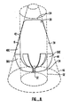
- the first end surface 30 and the second end surface 34 are connected by a sidewall 38.
- the sidewall 38 defines the cross-sectional area at any point along the longitudinal extent of the separation chamber 16, which varies in such a way that the cross-sectional area in the region adjacent to the first end surface 42 is less than the cross-sectional area in the region adjacent to the second end surface 44.
- the sidewall 38 defines a substantially conical surface i.e. , lies substantially along an imaginary cone 46. as best seen in Fig. 8.
- Extending inward from the sidewall 38 into the interior of the separation chamber 16 are one or more upper fins 48.
- the apices, or inward-most extent of the upper fins 48 define a cylinder, i.e. , lie substantially along an imaginary cylindrical surface 52.
- the upper fins 48 act to position and guide movement of an interior body, as described more fully below, and can also form a surface of a capillary region or volume in cooperation with the sidewall 38, as described more fully below. Because whether a region or volume will have a capillary action on a fluid depends on the characteristics of the fluid, principally the surface tension thereof. the geometry and dimensions of a capillary volume must be defined in relationship to the fluid. In the present case, a contemplated use of the invention is separation of liquid from exhaled gases. In many instances, the liquid will be substantially water, and thus the present invention includes volumes which are capillary volumes with respect to water. As noted above, however, in many medical applications, the liquid will include an amount of typically viscous body fluids, so that preferably the capillary volumes will be capillary with respect to fluids which are more viscous than water.
- the upper fins 48 extend only partly along the longitudinal extent of the sidewall 38 and are sufficiently spaced from the first outlet port 28 to prevent any capillary conveyance of liquid to the vicinity of the outlet port 28, such as might result in movement of liquid through the first outlet port 28.
- the first end surface 30 is substantially shaped as a segment of a sphere, such as a hemisphere, with a planar portion 54 to assist in occlusion of the first outlet port 28. as described more fully below.
- the first outlet port 28 is preferably centrally located in the planar portion 54.
- the second outlet port 32 is adjacent to, and preferably formed in, the second end surface 34.
- the second end surface 34 is preferably shaped as a segment of a sphere, such as a hemisphere.
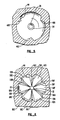
- a plurality of lower fins 56 project inward from the second end surface 34 into the interior of the separation chamber 16, as best seen in Fig. 7.
- the lower fins 56 act to position a solid body in the separation chamber 16 and to define capillary regions or volumes, as described more fully below.
- the lower fins 56 are substantially trapezoidal in cross section so that the innermost extensions or surfaces 58 of the lower fins 56 are substantially flat.
- the flat surfaces 58 define a spherical surface, i.e. , lie along a sector of an imaginary sphere, substantially parallel to the second end surface 34.
- the fins 56 in cooperation with the second end surface 34, form walls of capillary regions or volumes.
- the capillary volumes include the interstices 62a-62f between the lower fins 56. It has been found that a converging configuration of capillary volumes 62, such as that depicted in Figs. 1-8, is effective to convey liquid towards the second outlet port 32 with sufficient efficiency that even when the liquid has a viscosity higher than water, the amount of gas flow or blow down needed to convey the liquid away from the first outlet port 28 and into the reservoir 14 is less than in previous configurations.
- the efficiency is related to providing both capillary volumes 62, which taper towards the second outlet port 32, and a relatively large surface area in the second end surface 34 for accommodating more capillary volumes 62.
- the tapering of the sidewall 38 is consistent with both the desirably of a large surface area for the second end surface 34, and the desirability of a small total volume for the separation chamber 16.
- the present invention is operable when tipped, such as at angles up to about 90°, so that gravity is not acting in a direction toward the second outlet port, and is also operable in low or zero gravity environments.
- the angle of corners affects the degree of capillary action of a capillary volume. Accordingly, in the preferred embodiment, the angle 64 which the lower fins 56 make with the second end surface 34 is preferably less than or equal to about 135°. This angular relationship is preferably also used in the upper fins 48.
- a solid body such as a ball bearing 66 is disposed in the separation chamber 16 to also define surfaces of capillary volumes.
- the ball bearing 66 is positionable to substantially contact the flat surfaces 58 of the lower fins 56 and, in this position, to form an additional surface to define the capillary volumes 62.
- the capillary volumes 62a-62f are defined by the fins 56a-56f, the second end surface 34, and portions of the surface of the ball bearing 66. The presence of the ball bearing has been found to increase the efficiency of the capillary action.
- the solid body is fixed. such as by gluing, in a position away from the first outlet port 28 and proximate to, but spaced from, the second outlet port, such as the position 66 depicted in Fig. 3, to be in a non-sealing relationship with the second outlet port 32.
- the ball bearing 66 is also operable to provide other functions. Because the ball bearing occupies a certain amount of space in the separation chamber 16, the effective volume (i.e. , the dead space or volume available for the gas) is reduced, thus reducing or preventing degradation of the gas analysis signal because of excessive gas mixing in the separation chamber 16.
- the ball bearing 16 can act to occlude the first outlet port 28 when such is desired. For example, it may be desired to occlude the first outlet port 28 whenever the separation chamber 16 is tipped out of its preferred vertical alignment, depicted in Fig. 3, beyond a predetermined maximum tipping angle, such as tipping to such a degree that liquid in the separation chamber 16 or reservoir 14 will flow through the first outlet port 28.
- the upper fins 48 are configured to guide the ball bearing 66 from the lower position depicted in Fig. 3 to an upper position 68, shown in phantom lines. It is for this reason that the upper fins 48 define a substantially cylindrical surface 52 for passage of the substantially spherical ball bearing 66. It has been found that the desired seating of the ball bearing 66 to occlude the first outlet port 28 is facilitated by provision of the planar region 54 around the first outlet port 28.
- the maximum tipping angle, beyond which it is desired to occlude the first outlet port 28, will depend on the configuration of the separation chamber 16 and the outlet ports 28, 32. In part because of the upward tapering configuration of the sidewall 38, a larger tipping angle can be tolerated in the present invention than could be tolerated by previous downward tapering configurations. In general terms, the maximum tipping angle will be that angle at which either a portion of the sidewall 38 is angled sufficiently downward with respect to gravity to permit liquid to flow into the first outlet port 28, or at which liquid in the reservoir 14 can freely flow into the separation chamber 16 under the influence of gravity. Accordingly, the maximum tipping angle is affected by the geometry of the separation chamber 16 and reservoir 14.
- the downward tapering of the separation chamber permits toleration of a larger tipping angle than could be permitted with an untapered or oppositely tapered chamber. Further, the extension of the first and second tubes. 19, 35 into the reservoir 14 permits some degree of tipping (and thus, pooling of liquid near the top of the reservoir 14) before liquid can pass back into the separation chamber 16.
- the angle at which the ball bearing 66 moves to the second or upper position 68 can be adjusted or affected by the configuration of the sidewall 38 or upper fins 48 so that movement is controlled only by gravitational forces.
- a device is provided to position and maintain the ball bearing 66 in the upper position 68 upon tipping beyond a predetermined angle.
- the device for positioning and maintaining the ball bearing 66 in the upper position 68 is an array of four magnets 72A-D. A number of advantages are obtained by using a positioning device such as a magnet 72.
- the strength of the magnets 72A-D can be adjusted so that they are effective to position the ball bearing 66 in the upper position 68 as soon as the ball bearing 66 has moved to within a predetermined distance of the magnets 72A-D. such as from tipping of the separation chamber 16. In this manner, it is possible to adjust the tipping angle at which the ball bearing 66 is moved to the upper, occluding position 68.
- an electromagnet rather than a permanent magnet, the strength of the magnetic field can be calibrated to adjust the maximum permissible tipping angle, or the electromagnet can be activated by an angle-sensing device (not shown).
- the overall cost of the separator 10 is maintainable at a level which permits the separator 10 to be used in a disposable fashion.
- the magnets 72A-D are positioned slightly above the center of the ball bearing 66 when the ball bearing is in the upper position 68.
- the housing 74 preferably contains apparatus, such as resilient sleeve 75, for holding the separator 10 in position so as to permit easy detachability and replacement of the separator 10 consistent with its preferred use as a disposable member.
- the housing 74 also contains a passageway 78 for conveying gas from the first outlet port 28 to the gas analyzer 82, which can be any gas analyzer, such as an infrared capnogram or others well known in the art.
- Fig. 7 depicts a preferred manner of assembly of the device.
- the device is preferably formed from three sections, an upper manifold section 84, a lower manifold section 86, and a reservoir section 88.
- the preferred material of construction is a clear polycarbonate material, other materials, such as metal, resins, plastics, and the like, can be used.
- the parts are preferably formed by molding, such as injection molding, but can be formed by other processes, such as stamping, milling, and the like.
- the parts 84, 86, 88 are preferably joined by a bonding technique, such as ultrasonic welding, although they can also be joined by adhesion, screwing, bolting, and other well known methods.
- the interior volume of the separation chamber 16 is approximately 0.1 ml.
- the ball is 0.172 inches (about 4.4 mm) in diameter, and the imaginary cylinder defined by the upper fins has a diameter of about 0.18 inches (about 4.6 mm).
- the lower fins 56 define a spherical sector with a 0.184 inch diameter, whose center is 0.006 inches (about .15 mm) above the plane of the parting line.
- the second end surface 34 lies along a sphere of 0.224 inches in diameter (about 5.7 mm) whose center is coincident with the center of the sphere defined by the lower fins 56.
- the inlet port 22, first outlet port 28, and second outlet port 32 have diameters of approximately 0.03 inches (about 0.75 mm).
- the reservoir 14 has a capacity of about 0.3 cubic inches (about 5 ml).
- the upper end surface 30 lies partially along a spherical sector with a radius of 0.09 inches (about 2.3 mm).
- the fluid entering inlet port 22 is a mixture of gas and liquid, the liquid typ ically being liquid which has condensed from the gas as it has cooled.
- the liquid impacts the interior surfaces of the separation chamber 16 and the ball bearing 66, and accumulates or coalesces in the capillary volumes 62.
- the coalescence in the capillary volumes 62 can be accomplished or enhanced by ordinary gravity drainage of droplets down the sidewall 38 and/or capillary conveyance along capillary volumes formed between the upper fins 48 and the sidewall 38.
- the liquid is directed, by capillary action and/or gravitational action, away from the first outlet port 28 and towards the second outlet port 32.
- the reservoir 14 is preferably provided with an absorbent material 92 to assist in preventing flow of liquid from the reservoir 14 into the separation chamber 16, such as upon tipping of the reservoir 14.
- the absorbent material 92 expands upon wetting, and can be used to provide a visual indication of the amount of liquid in the reservoir 14, such as by providing a view port or window in the reservoir 14 or by forming reservoir 14 of a substantially transparent material.
- the separator 10 can be removed from the housing 74 and replaced by a new separator 10. Because substantially all patient-wetted surfaces are contained in the separator 10 or are upstream thereof, replacement of a separator 10 with a sterile separator prevents contamination of a new patient.
- a removed separator 10 is disposed of, whereas the housing 74 is reusable.
- the ball bearing 66 When the separation chamber 16 is tipped beyond a predetermined angle, as described above, the ball bearing 66 is brought within the influence of a magnet 72, and the magnet positions the ball bearing 66 adjacent to and seating with respect to the first outlet port 28 to prevent the passage of liquid through the first outlet port 28.
- Capillary action in the present configuration is sufficiently effective to permit reduction of the blow down ratio, such as reduction below 15% even when fluids more viscous than water are separated.
- Upward tapering sidewalls provide for increased surfaces for capillary volumes in lower portions and increase in the permissible tipping angle without excessive increase in the volume of the separation chamber 16.
- a solid body, such as a ball bearing provides for an additional surface for definition of capillary volumes, provides for a decrease in the effective volume of the separation chamber, and is usable for selective occlusion of the first outlet port, for example, upon tipping beyond a predetermined angle.
- the apparatus is inexpensively made, consistent with disposable use.
- the separator 10 is detachable in such a way that patient-wetted surfaces are removable from the housing to assist in preventing contamination from one patient to another.
- the separator 10 is capable of operation in positions of up to 90° from the vertical, or in reduced or zero gravity conditions. The device will automatically shut off flow to the second outlet port if predetermined conditions of acceptable orientation are exceeded, thus preventing liquid from fouling the measuring device.
- the sidewall of the separation chamber can be formed in a tapering configuration other than a conical configuration.
- the solid body, which is movable in the separation chamber can be a body other than a ball bearing and other than a spherical body, although it is preferably gas-impermeable.
- the upper fins can define an imaginary surface other than a cylindrical surface, particularly in cooperation with a non-spherical movable body. Fins with non-triangular or non-trapezoidal cross sections are usable, although flat surfaces of contact with the movable body, particularly with respect to the lower fins, assist in preventing damage from impact between the movable body and the fins.
- the upper and lower end surfaces can have other than spherical sector configurations, consistent with channeling of flow to the outlet ports.
- Devices for positioning and maintaining the ball bearing in the upper position other than a magnet, can be used, such as springs, electric devices, hydraulic or fluid devices, and the like.
- a gas analyzer other than an infrared capnographic analyzer, can be used and the separator 10 can be used in non-gas analyzer contexts. such as any context in which it is desired to separate a liquid from a gas.
- the separator can be provided in a reusable and/or sterilizable configuration.
Landscapes
- Health & Medical Sciences (AREA)
- Life Sciences & Earth Sciences (AREA)
- Chemical & Material Sciences (AREA)
- Engineering & Computer Science (AREA)
- Physics & Mathematics (AREA)
- Molecular Biology (AREA)
- General Health & Medical Sciences (AREA)
- Pathology (AREA)
- Biomedical Technology (AREA)
- General Physics & Mathematics (AREA)
- Immunology (AREA)
- Biochemistry (AREA)
- Analytical Chemistry (AREA)
- Medicinal Chemistry (AREA)
- Biophysics (AREA)
- Food Science & Technology (AREA)
- Physiology (AREA)
- Medical Informatics (AREA)
- Urology & Nephrology (AREA)
- Pulmonology (AREA)
- Public Health (AREA)
- Animal Behavior & Ethology (AREA)
- Hematology (AREA)
- Surgery (AREA)
- Veterinary Medicine (AREA)
- Heart & Thoracic Surgery (AREA)
- Chemical Kinetics & Catalysis (AREA)
- Combustion & Propulsion (AREA)
- Investigating Or Analysing Biological Materials (AREA)
- Sampling And Sample Adjustment (AREA)
- Separating Particles In Gases By Inertia (AREA)
- Measurement Of The Respiration, Hearing Ability, Form, And Blood Characteristics Of Living Organisms (AREA)
Applications Claiming Priority (2)
| Application Number | Priority Date | Filing Date | Title |
|---|---|---|---|
| US25555388A | 1988-10-07 | 1988-10-07 | |
| US255553 | 1988-10-07 |
Publications (2)
| Publication Number | Publication Date |
|---|---|
| EP0362889A2 true EP0362889A2 (de) | 1990-04-11 |
| EP0362889A3 EP0362889A3 (de) | 1990-04-25 |
Family
ID=22968841
Family Applications (1)
| Application Number | Title | Priority Date | Filing Date |
|---|---|---|---|
| EP89118632A Withdrawn EP0362889A3 (de) | 1988-10-07 | 1989-10-06 | Gas-Flüssig-Mikrovolumen-Trennapparat und Verfahren |
Country Status (3)
| Country | Link |
|---|---|
| EP (1) | EP0362889A3 (de) |
| JP (1) | JPH03502072A (de) |
| WO (1) | WO1990003835A1 (de) |
Cited By (4)
| Publication number | Priority date | Publication date | Assignee | Title |
|---|---|---|---|---|
| EP0559929A1 (de) * | 1992-03-09 | 1993-09-15 | Siemens Aktiengesellschaft | Anordnung zum Entfernen von Störkomponenten aus Messgasen für die Gasanalyse |
| EP0555543A3 (de) * | 1992-02-12 | 1994-04-27 | Rbr Computertechnik Gmbh | |
| EP1177765A1 (de) * | 2000-08-03 | 2002-02-06 | GE Marquette Medical Systems, Inc. | Verfahren und Vorrichtung zur Trennung von Wasser und Gas in einem Gasanalysegerät |
| DE102005005231A1 (de) * | 2005-01-31 | 2006-08-10 | Fraunhofer-Gesellschaft zur Förderung der angewandten Forschung e.V. | Vorrichtung mit einem ein Medium führenden Kanal und Verfahren zur Entfernung von Einschlüssen |
Families Citing this family (1)
| Publication number | Priority date | Publication date | Assignee | Title |
|---|---|---|---|---|
| WO1993025142A2 (en) * | 1992-06-16 | 1993-12-23 | Natus Medical, Inc. | In vivo measurement of end-tidal carbon monoxide concentration apparatus and methods and filters therefor |
Family Cites Families (4)
| Publication number | Priority date | Publication date | Assignee | Title |
|---|---|---|---|---|
| US3996027A (en) * | 1974-10-31 | 1976-12-07 | Baxter Laboratories, Inc. | Swirling flow bubble trap |
| DE2820916C3 (de) * | 1978-05-12 | 1980-11-27 | Sachs Systemtechnik Gmbh, 8720 Schweinfurt | Mundstück für den Meßkopf eines Redoxgasmeßgeräts |
| US4446869A (en) * | 1983-03-07 | 1984-05-08 | Trimed, Inc. | Water absorbing trap to protect an infrared exhaled carbon dioxide apnea monitor of a patient's respiration |
| US4713095A (en) * | 1986-10-16 | 1987-12-15 | Criticare Systems, Inc. | Liquid separator for gas analyzer |
-
1989
- 1989-10-05 WO PCT/US1989/004411 patent/WO1990003835A1/en not_active Ceased
- 1989-10-05 JP JP1511242A patent/JPH03502072A/ja active Pending
- 1989-10-06 EP EP89118632A patent/EP0362889A3/de not_active Withdrawn
Cited By (6)
| Publication number | Priority date | Publication date | Assignee | Title |
|---|---|---|---|---|
| EP0555543A3 (de) * | 1992-02-12 | 1994-04-27 | Rbr Computertechnik Gmbh | |
| EP0559929A1 (de) * | 1992-03-09 | 1993-09-15 | Siemens Aktiengesellschaft | Anordnung zum Entfernen von Störkomponenten aus Messgasen für die Gasanalyse |
| EP1177765A1 (de) * | 2000-08-03 | 2002-02-06 | GE Marquette Medical Systems, Inc. | Verfahren und Vorrichtung zur Trennung von Wasser und Gas in einem Gasanalysegerät |
| DE102005005231A1 (de) * | 2005-01-31 | 2006-08-10 | Fraunhofer-Gesellschaft zur Förderung der angewandten Forschung e.V. | Vorrichtung mit einem ein Medium führenden Kanal und Verfahren zur Entfernung von Einschlüssen |
| US7887621B2 (en) | 2005-01-31 | 2011-02-15 | Fraunhofer-Gesellschaft zur Förderung der angewandten Forschung e. V. | Device with a channel conducting a flowable medium and a method for removing inclusions |
| DE102005005231B4 (de) * | 2005-01-31 | 2012-04-19 | Fraunhofer-Gesellschaft zur Förderung der angewandten Forschung e.V. | Vorrichtung mit einem ein Medium führenden Kanal und Verfahren zur Entfernung von Einschlüssen |
Also Published As
| Publication number | Publication date |
|---|---|
| WO1990003835A1 (en) | 1990-04-19 |
| EP0362889A3 (de) | 1990-04-25 |
| JPH03502072A (ja) | 1991-05-16 |
Similar Documents
| Publication | Publication Date | Title |
|---|---|---|
| US4997463A (en) | Gas-liquid microvolume separating apparatus and method | |
| US3939822A (en) | Disposable blood collection and filtering device | |
| US5857461A (en) | Multiple channel sample port | |
| CA2196717C (en) | Air eliminator | |
| US5514341A (en) | Feces-sampling transport container | |
| US5156811A (en) | Pipette device | |
| AU619491B2 (en) | Two chambered autotransfuser device and method of use | |
| US5131387A (en) | Moisture trap | |
| ES2361354T3 (es) | Adaptador de vial con ventilación con filtro para retención de aerosol. | |
| US20090014391A1 (en) | Buoy Suspension Fractionation System | |
| JPS60502091A (ja) | 気体出口付きフィルターホルダー | |
| IE71035B1 (en) | Drainage device | |
| EP0362889A2 (de) | Gas-Flüssig-Mikrovolumen-Trennapparat und Verfahren | |
| JP2018175878A (ja) | 液体ガス分離装置 | |
| US5102400A (en) | Drip chamber for infusion apparatus | |
| CA2086658A1 (en) | Device for removal of gas from a liquid in any orientation | |
| JPS63185410A (ja) | ガス分析装置用液体分離器 | |
| CA2331855A1 (en) | Plasma retention structure providing internal flow | |
| US4579568A (en) | Gas analyzer separator | |
| CA1077297A (en) | Capillary collection and dispensing device for non-pressurized liquid | |
| US20030024528A1 (en) | Moisture trap | |
| CN101878430B (zh) | 喷嘴装置和液体试样分析装置 | |
| US4957629A (en) | Obstetrical filter and trap | |
| JP7748199B2 (ja) | サンプル捕獲および抽出のための装置、システム、および方法 | |
| JPH0712808A (ja) | 輸送採便容器 |
Legal Events
| Date | Code | Title | Description |
|---|---|---|---|
| PUAI | Public reference made under article 153(3) epc to a published international application that has entered the european phase |
Free format text: ORIGINAL CODE: 0009012 |
|
| PUAL | Search report despatched |
Free format text: ORIGINAL CODE: 0009013 |
|
| AK | Designated contracting states |
Kind code of ref document: A2 Designated state(s): DE FR GB |
|
| AK | Designated contracting states |
Kind code of ref document: A3 Designated state(s): DE FR GB |
|
| 17P | Request for examination filed |
Effective date: 19900801 |
|
| 17Q | First examination report despatched |
Effective date: 19920311 |
|
| STAA | Information on the status of an ep patent application or granted ep patent |
Free format text: STATUS: THE APPLICATION IS DEEMED TO BE WITHDRAWN |
|
| 18D | Application deemed to be withdrawn |
Effective date: 19920922 |